Figure 8-1 Sunlight passing through openings between partially overlapping leaves suggests that light moves in straight lines. However, such “rays” would be invisible without light scattering caused by mist in the air (eg, Tyndall effect). Likewise, the beam of a slit lamp is not normally visible in the anterior chamber but becomes so when light is scattered by the presence of abnormal proteins or cells. (Illustration by Edmond H. Thall, MD.)
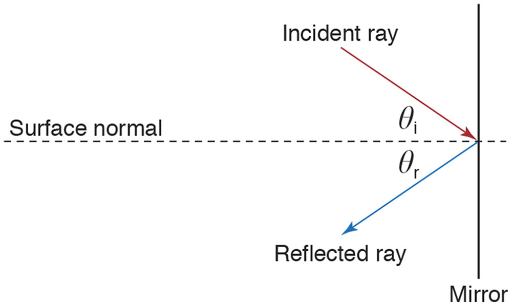
Figure 8-2 The law of reflection states that an incident ray rebounds symmetrically after striking a smooth surface. The angles of incidence (θi) and reflection (θr) are defined with respect to an imaginary line, the surface normal. The law states that (1) the incident ray, reflected ray, and surface normal are coplanar, and (2) θi equals θr. (Illustration by Edmond H. Thall, MD.)
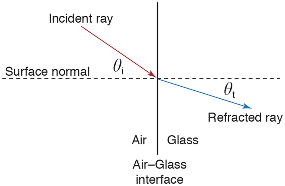
Figure 8-3 Light moving from one material to another abruptly changes speed (refraction) and usually direction. The angles of incidence (θi) and transmission (θt) are defined with respect to the surface normal. The incident ray, refracted ray, and surface normal are coplanar. θi and θt are related by the equation n1 sin θi = n2 sin θt. The approximation n1 θi = n2 θt is sufficiently accurate for small angles. (Illustration by Edmond H. Thall, MD.)
The corpuscular hypothesis lacked supporting experimental evidence. Nevertheless, it was accepted essentially unchallenged for 2000 years.
Diffraction
According to the corpuscular theory, collimated light should remain so after traversing an aperture. Actually, the beam diverges, violating the law of rectilinear propagation (Fig 8-4). All apertures produce diffraction to some extent. The smaller the aperture is relative to the wavelength, the more pronounced is the consequent diffraction (Fig 8-5).
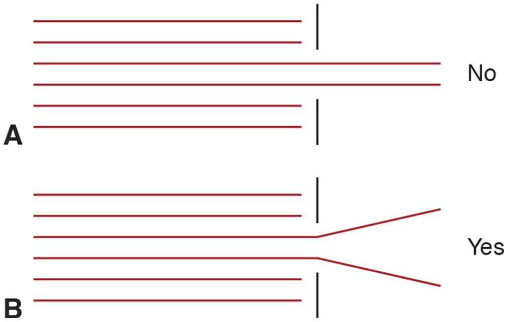
Figure 8-4 Behavior of light crossing an aperture. A, According to the corpuscular theory of light, a collimated beam should remain so after crossing an aperture that blocks the sides of the beam. B, Instead, the beam diverges. This phenomenon, called diffraction, violates the law of rectilinear propagation and suggests that light is a wave, not a series of particles (corpuscular). (Illustration by Edmond H. Thall, MD.)
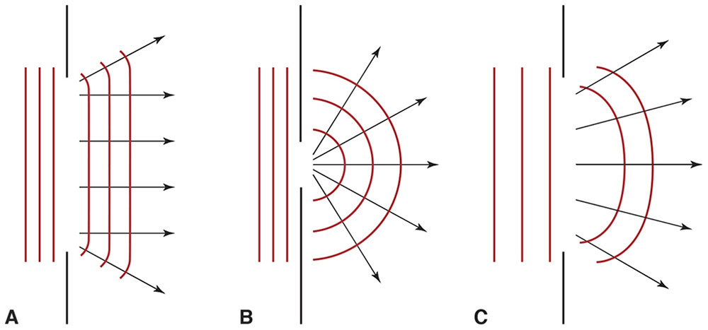
Figure 8-5 A, According to the law of rectilinear propagation, light should not change direction after traversing an aperture. B, In reality, apertures do cause light to change direction—a phenomenon called diffraction. C, The smaller the aperture is relative to the wavelength of incident light, the more pronounced is the diffraction. (Illustration by Edmond H. Thall, MD.)
Some scientists believed that the discovery of diffraction (c 1665) offered sufficient justification to abandon the corpuscular theory completely, and they concluded that light was fundamentally a wave. Sir Isaac Newton and others, however, believed that the corpuscular theory could explain diffraction. For the next 100 years, the nature of light—wave or particle—was an open question.
The Speed of Light
In 1687, Danish astronomer Ole Roemer noted an irregularity in the orbit of Jupiter’s moon Io that he attributed to light having a finite speed. Later laboratory measurements confirmed that the speed of light is finite.
By international agreement, a meter had been defined by the length of a metal bar kept in Paris, France. Because this standard meter bar might be damaged or destroyed by war or natural disaster, the international community adopted a standard of measurement based on natural phenomena that are readily accessible and indestructible. Hence, the speed of light became the measurement standard, and the meter is defined as the distance light travels in a vacuum during 1/299,792,458 second. Thus, the speed of light is by definition exactly 299,792,458 m/s. A useful approximation for the speed of light in a vacuum is 3 × 10⁸ m/s (approximately 1 ft/ns).
The Superposition of Waves
The superposition principle states that when 2 or more waves overlap, their amplitudes will add or cancel. The superposition of 2 waves of differing frequencies produces a changing “interference” pattern of reinforcement and cancellation that, in the case of light, is much too fast to be observed (Fig 8-6). However, the superposition of 2 waves of identical frequency produces a stable interference pattern (Fig 8-7).
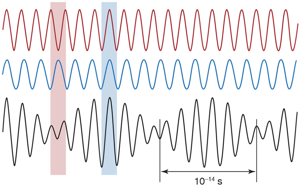
Figure 8-6 According to the principle of superposition, when 2 waves overlap, their amplitudes add, producing a single resultant wave. The 2 waves at top differ slightly in frequency and align peak to peak (blue band), reinforcing each other in some places, and peak to trough (red band), canceling each other in some places. In this example, complete cancellation does not occur because the waves differ in amplitude. In any case, the pattern alternates between reinforcement and cancellation about every 10–14 second—much too fast to be observed. (Illustration by Edmond H. Thall, MD.)
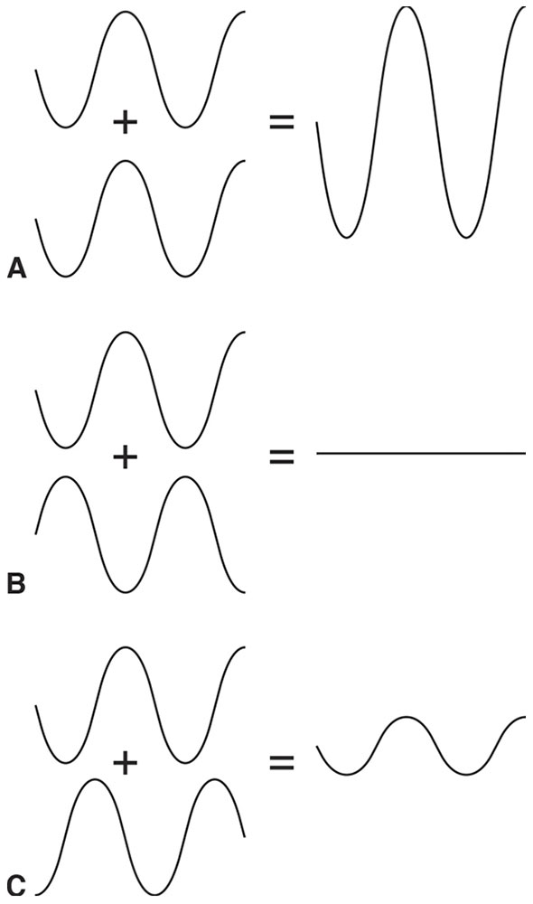
Figure 8-7 Overlapping waves of identical frequency and amplitude produce stable interference patterns. A, Waves overlap in phase—peaks coincide with peaks and troughs with troughs—producing a resultant wave of twice the amplitude. B, Waves overlap out of phase—the peak of one wave coincides with the trough of the other—and the waves cancel. C, Waves partially overlap—neither completely in nor out of phase—producing a wave of intermediate amplitude (between zero and twice the amplitude). (Illustration developed by Edmond H. Thall, MD, and redrawn by C. H. Wooley.)
The result of 2 particles striking the same place simultaneously is always additive, whereas 2 overlapping waves may reinforce or cancel each other, as just described. In 1801, London physician Thomas Young demonstrated that light can produce patterns of cancellation and reinforcement, thus providing strong evidence that light is a wave phenomenon.
Coherence
Light from most sources consists of wave trains. Just as a train has many cars, a wave train consists of many sections, each having a dominant frequency (Fig 8-8). Temporal coherence is a function of the bandwidth of a light source (ie, the number of frequencies it is composed of). Wave trains from broadband light sources (ie, those radiating many frequencies) consist of short sections, whereas narrowband light sources consist of wave trains with longer sections. The length of one wave train section is the coherence length. The time required for light to travel one coherence length is the coherence time.
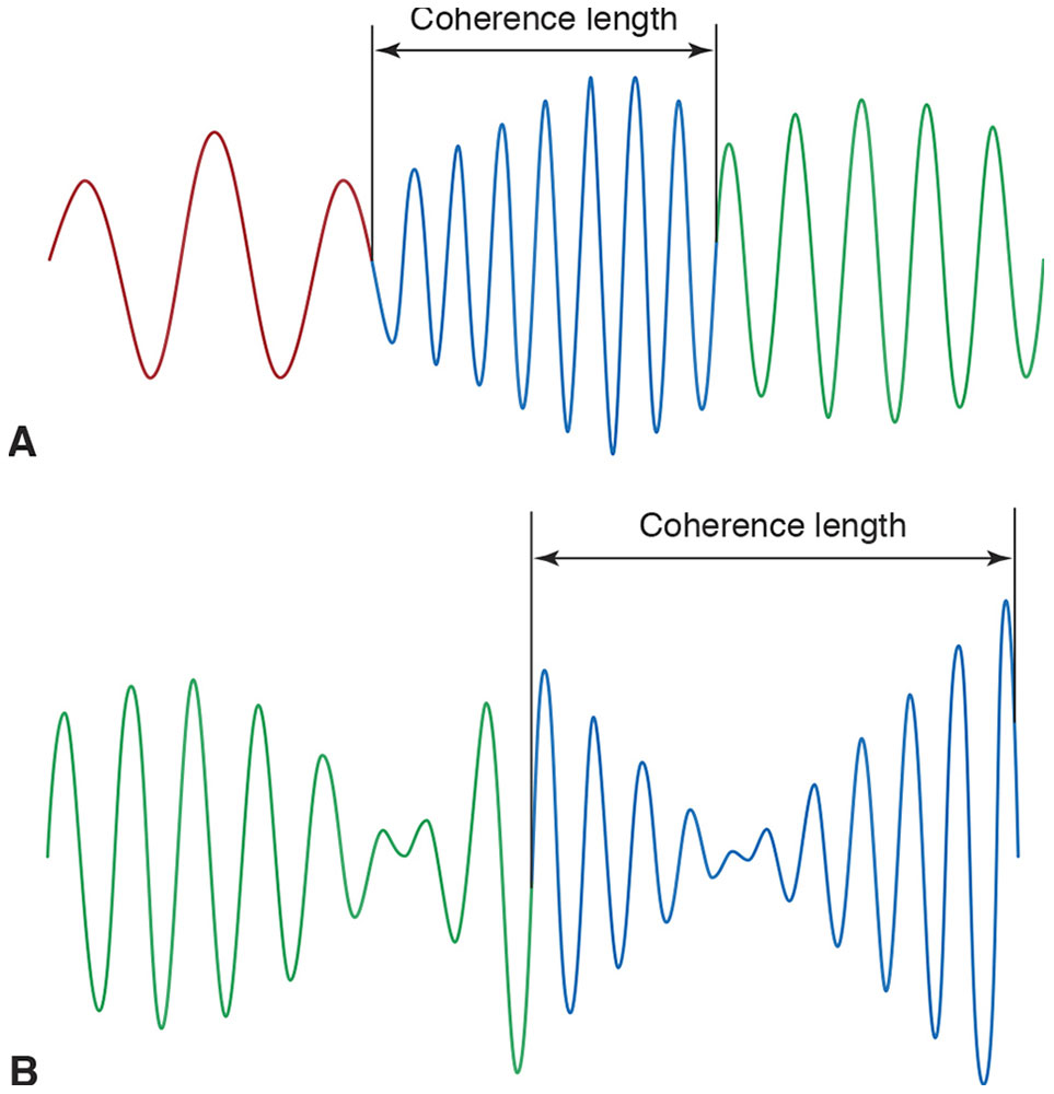
Figure 8-8 Each section of a wave train has a dominant frequency that changes randomly from one section to the next. The color of each section corresponds to its dominant frequency—eg, in A, the red section is lower in frequency, and the blue section is higher in frequency. The length of each section is the coherence length. A, Broadband wave trains have a short coherence length. B, Compared with A, the light represented in B has a narrower bandwidth and consequently a longer coherence length. (Illustration by Edmond H. Thall, MD.)
Consider a single section of a wave train from a broadband point source illuminating 2 small, closely spaced pinholes in an otherwise opaque screen (Fig 8-9A). Each section arrives at both pinholes simultaneously and is diffracted by the pinholes. The distance from each pinhole to point O is identical, so both sections produce a bright spot by constructive (ie, additive) interference.
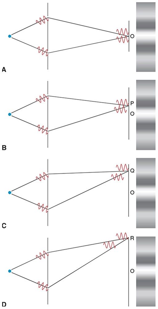
Figure 8-9 Schematic of Young’s experiment demonstrating that light is a wave phenomenon. A, Wave train sections arrive at the pinholes simultaneously, then diffract and arrive simultaneously at point O. They constructively interfere, producing a bright spot. B, To reach point P, one section travels slightly farther than the other, which lags behind by half a wavelength. The 2 sections interfere destructively, and point P is dark. C, At point Q, one section lags behind the other by 1 full wavelength. The 2 sections interfere constructively, producing a reduced bright spot. D, At point R, one section lags the other by more than 1 coherence length so there is no interference, but a superposition of noncorresponding sections produces an average uniform illumination. (Illustration by Edmond H. Thall, MD.)
At point P (Fig 8-9B), one section travels half a wavelength farther than the other, so the 2 sections cancel, producing a dark spot by destructive (ie, subtractive) interference. At point Q (Fig 8-9C), the sections differ by a full wavelength and again produce a bright spot by constructive interference. Alternating intervals of constructive and destructive interference produce a fringe pattern. However, as the distance from point O increases, the wave train sections overlap less and less, decreasing the degree of fringe contrast (ie, the difference in intensity between the brightest and darkest points). At point R (Fig 8-9D), one section lags the other by more than its coherence length, so the sections do not overlap at all. Because the superposition of nonidentical sections does not produce stable interference, fringes are no longer visible.
Sunlight (composed of numerous frequencies) has a coherence length of 1–2 µm, whereas laser light (composed of few frequencies) typically has a coherence length of several centimeters. If the point source in Figure 8-9 were to be replaced by a laser light source, many more fringes of much higher contrast would be generated.
Another aspect of coherence concerns a light source’s physical size (ie, length or area). Consider a second point source illuminating 2 pinholes (Fig 8-10). Fringes produced by the second source are shifted slightly relative to the first. When the 2 fringe patterns are combined, the result is lower-contrast fringes. If the light source consists of many point sources distributed over a broad area, the net result will be a total loss of contrast and no fringes will be evident. Spatial coherence refers to the size of the light source, which must be small to produce visible fringes.
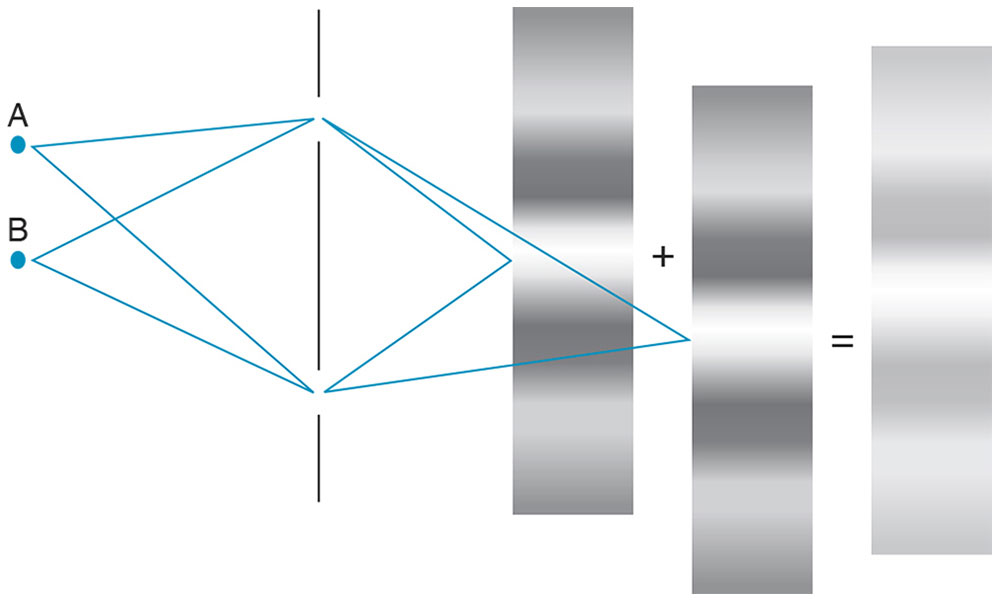
Figure 8-10 The effect of the size of a light source on spatial coherence. The interferometer fringe pattern produced by a second point source (point B) of light is shifted relative to the first point source (point A). Superimposing both patterns results in a new pattern with decreased fringe contrast. A small light source has high spatial coherence and produces high-contrast fringes. If a light source is too large (ie, consists of numerous point sources), no fringes will be seen. (Illustration by Edmond H. Thall, MD.)
Electromagnetic Waves
The corpuscular theory of light was abandoned after Young provided strong evidence that light is a wave phenomenon. The next question is, What type of wave? James Clerk Maxwell developed equations describing the behavior of electric and magnetic fields. Maxwell discovered that oscillating electric fields (ie, those that rhythmically reverse polarity) are inextricably linked to oscillating magnetic fields and that such electromagnetic (EM) fields can radiate as waves. In 1862, Maxwell calculated the speed of EM waves and found that they moved at the speed of light, and he thus concluded that light is an EM wave. Several phenomena can be explained by the EM wave theory.
Polarization
The electric field of an EM wave oscillates perpendicularly to its magnetic field, and both oscillate perpendicularly to their direction of propagation (Fig 8-11). Because the electric and magnetic fields oscillate in lockstep, for simplicity only the electric field is shown in most illustrations. The EM plane of polarization is defined by the orientation of the electric-field oscillation (eg, vertical in Fig 8-11) and direction of propagation. In general, the plane of polarization of an EM wave may have any orientation (ie, horizontal, vertical, or oblique).
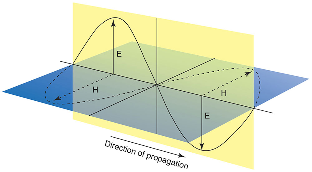
Figure 8-11 Light is polarized. The plane of polarization is specified with reference to the direction of propagation and the direction of the oscillating electric (E) or magnetic (H) field, which always oscillate perpendicularly to each other. In this view, the electric field is polarized vertically and the magnetic field horizontally, but they could be interchanged, or polarization could be in any oblique meridian. (Illustration by Jonathan Clark.)
Note that there is no such thing as “unpolarized” light. Typically, the plane of polarization changes rapidly (about every 10–13 to 10–14 second) and randomly, resulting in light that is randomly polarized. Linearly polarized light, however, has a single unchanging plane of polarization. In circularly polarized light, the plane of polarization rotates, and the (maximum) electric-field vector traces a corkscrew pattern as the wave propagates. Viewed head-on, the field vector traces a circle. In elliptically polarized light, which represents a more general case of circular polarization, the plane of polarization rotates as the wave propagates, but the (maximum) electric-field vector traces an ellipse instead of a circle.
Refractive Index and Dispersion
EM waves travel fastest in a vacuum and slower in any transparent material medium. All EM frequencies travel at the same speed in vacuum, but in any transparent medium, each frequency travels at a different speed—a phenomenon called dispersion. The refractive index (n) is the ratio of the speed of light in a vacuum divided by its speed in a given material. Dispersion is measured using the refractive index at 3 different wavelengths. This measurement, the Abbe number (V), is defined as

where nd, nF, and nC represent wavelengths (in a vacuum) of 587.6 nm, 486.1 nm, and 656.3 nm, respectively. Larger Abbe numbers indicate lower dispersion.
Reflection, Transmission, and Absorption
Consider light striking the interface between 2 materials such as air and glass (Fig 8-12). Some light is reflected according to the law of reflection and some transmitted (refracted) according to Snell’s law.
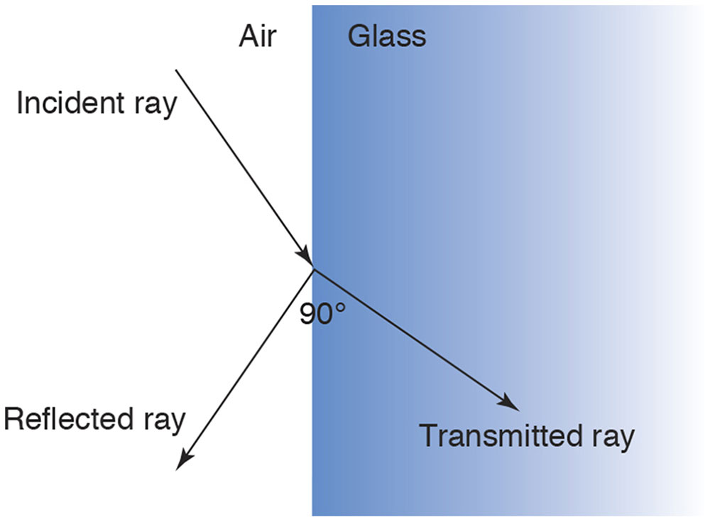
Figure 8-12 At the interface of 2 transparent media, some incident light is reflected and some is refracted (transmitted). The amount of reflected light increases as the angle of incidence increases, and the amount of light refracted decreases commensurately. When, as in this case, the reflected and refracted rays form a right angle, all the reflected light is linearly polarized parallel to the interface (ie, perpendicular to the plane of incidence). (Illustration by Edmond H. Thall, MD.)
The question is, How much light is reflected and how much transmitted? Applying electromagnetic wave theory, Fresnel demonstrated that the greater the difference in the refractive indices or the greater the angle of incidence, the greater the degree of reflection and, consequently, the less light transmitted. For an air–glass interface, typically about 4% of light is reflected at low angles of incidence. Tears have a lower refractive index than glass, so an air–tear-film interface reflects even less light—about 2%.
Light reflected at the front and back surfaces of the cornea and the crystalline lens produces the 4 Purkinje images. The reader should be able to rank the Purkinje images from brightest to dimmest in both phakic and pseudophakic eyes.
Fresnel also showed that reflected light tends to be linearly polarized parallel to the interface. Reflected light is completely polarized if the angle of incidence equals the Brewster angle:
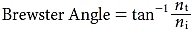
where nt and ni are the refractive indices of the transmitted and incident media, respectively. At the Brewster angle, all the reflected light is linearly polarized, but not all the linearly polarized light is reflected. Consequently, the transmitted light is a mixture of linearly and randomly polarized light.
When light moves from a higher to lower refractive index medium, it will be completely reflected (total internal reflection [TIR]) if the angle of incidence exceeds the critical angle:
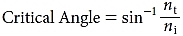
Note that the critical angle always exceeds the Brewster angle. TIR is what prevents visualization of the anterior chamber angle during slit lamp examination. In rare cases, the cornea might be so distorted that the angle is visible without gonioscopy, but usually some method must be employed to prevent TIR and make the angle visible.
Absorption is usually expressed as an optical density (OD). An OD of 1 represents a transmittance of 10%; an OD of 2, a transmittance of 1% (0.01); and an OD of 3, a transmittance of 0.1% (0.001). In general, the expression for optical density is
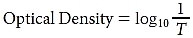
where T is the transmittance. (See Chapter 3 for a discussion of absorptive lenses.)
The Electromagnetic Spectrum
All EM radiation is fundamentally the same phenomenon, but its manifestations strongly depend on frequency. The frequency of EM radiation has no specific upper or lower limit. The spectrum is divided into regions in which the radiation is produced and detected by similar techniques; thus, various EM regions partially overlap (Fig 8-13).
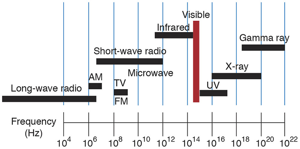
Figure 8-13 The electromagnetic (EM) spectrum. The spectrum is divided for practicality into regions in which the radiation is generated and detected by similar techniques and equipment; thus, various EM regions partially overlap. Notice the relatively small visible portion of the EM spectrum (red bar) compared with other portions. (Illustration by Edmond H. Thall, MD.)
For instance, “light” generally refers to the very narrow portion of the electromagnetic spectrum that stimulates the retina. However, the limits of the visible spectrum are not well defined because the sensitivity of the retina approaches zero asymptotically. If the limits are taken (arbitrarily) as the points where the eye’s sensitivity is 1% of maximum, then the visible spectrum spans the frequencies between 7.0 × 10¹⁴ Hz (λ = 430 nm) and 4.3 × 10¹⁴ Hz (λ = 690 nm). However, the eye can detect radiation, if sufficiently intense, beyond these limits.
Frequency and Color
Despite the use of terms such as blue light or red light, color is not a property of light but rather a phenomenon of perception. “Spectral colors” are perceived when an area of the retina is stimulated by a single frequency. The colors of the rainbow are spectral colors. Other color sensations not seen in the rainbow (eg, cyan, magenta) are perceived when multiple frequencies stimulate the same region of the retina simultaneously.
Energy in an Electromagnetic Wave
Light is both a form of energy and a means of conveying energy from one point to another. In EM wave theory, the energy carried by the wave is proportional to the square of its amplitude and does not depend at all on the frequency of the wave.
Quantum Theory
EM wave theory successfully explains “macroscopic” phenomena but fails to explain phenomena at the atomic and molecular levels. According to EM theory, electrons orbiting in an atom should constantly radiate EM waves, lose energy in the process, and ultimately crash into the nucleus—which, of course, does not happen. Thus, a new theory was required that would be capable of explaining the behavior of electrons in atoms and molecules.
The new theory—quantum theory—states that electrons in atoms (or molecules) exist in nonradiating states and that each state is associated with a specific energy level. The energy states possible for an atom differ from element to element, and those for a molecule differ from compound to compound. Each element or compound has a unique distribution of energy states (Fig 8-14).


