Figure 5-1 The major types of intraocular lenses (IOLs) and optics. A, Anterior chamber lens. B, Prepupillary lens (no longer used). C, Posterior chamber lens in the capsular bag. D, Posterior chamber lens in the ciliary sulcus. E, Biconvex optic. F, Planoconvex optic. G, Meniscus optic. (Redrawn by C. H. Wooley.)
Background
In the 1970s, surgeons implanting IOLs included those who used intracapsular cataract extraction (ICCE) and those who used small-incision phacoemulsification (phaco). The IOL optic was made from PMMA, with supporting haptics of metal, polypropylene, or PMMA. The rigidity of these materials required that the small phaco incision be enlarged for IOL insertion. However, following the introduction of a foldable optic (made from silicone) in the late 1980s, enlargement was no longer required, and the combination of phaco and IOL implantation became the standard of care.
The 2 basic lens designs currently in use are differentiated by the plane in which the lens is placed (posterior chamber or anterior chamber) and by the tissue supporting the lens (capsule/ciliary sulcus or chamber angle) (see Fig 5-1).
The effect of lens material on factors such as posterior capsular opacification (PCO) has been investigated. Earlier studies suggested that IOLs made from acrylic are associated with lower rates of PCO than are those made from silicone or PMMA. However, more recent studies suggest that lens edge design is a more important factor in PCO than is lens material, as Hoffer proposed in 1979 in the lens edge barrier theory. IOLs with an annular, ridge edge or a square, truncated edge create a barrier effect at the optic edge that reduces cell migration behind the optic and thus reduces PCO (Figs 5-2, 5-3, 5-4). The ridge concept led to the development of partial-ridge and meniscus IOLs, which were used for a time, and the sharp-edge designs now in use.
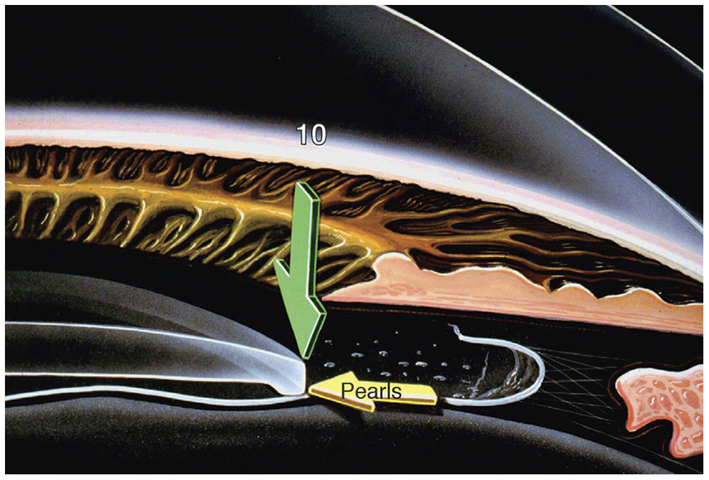
Figure 5-2 Schematic illustrating the concept of a tenfold increase in pressure (green arrow) at the edge of an IOL. (Courtesy of Kenneth J. Hoffer, MD.)
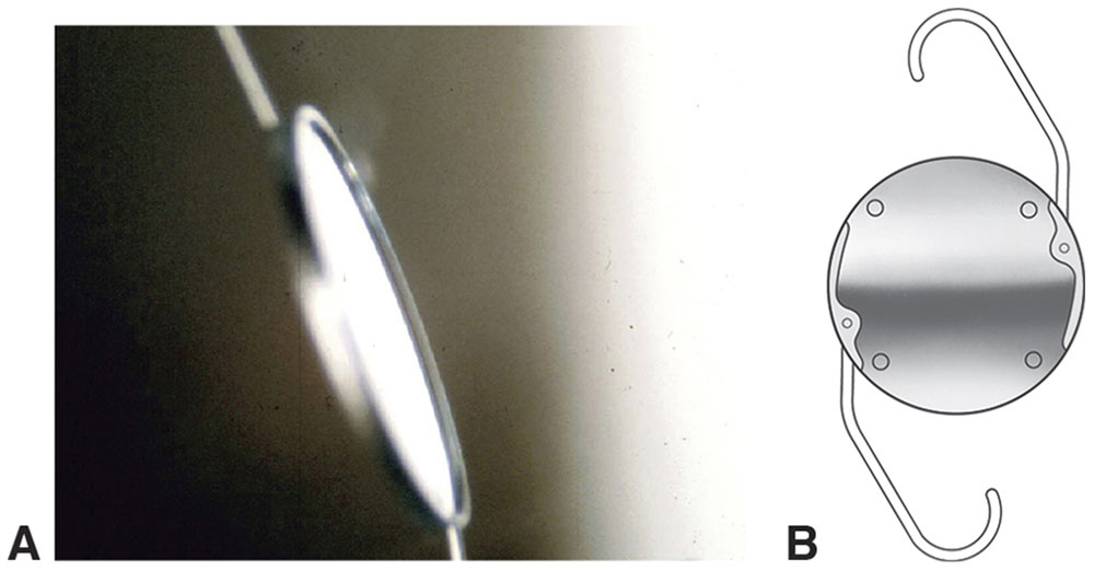
Figure 5-3 A, Hoffer annular ridge IOL. B, Kratz-Johnson posterior chamber IOL. (Courtesy of Kenneth J. Hoffer, MD; part B redrawn by C. H. Wooley.)
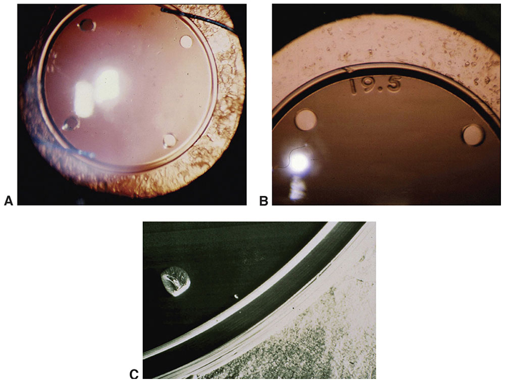
Figure 5-4 Increasing the pressure at the edge of an IOL leads to a blockage of cells to the central posterior capsule (A, B). C, The cell blockage as it appears on an electron micrograph. (Courtesy of Kenneth J. Hoffer, MD.)
Plano IOLs are available for patients whose eyes require zero (or minimal) power in the aphakic state (ie, patients with very high myopia). The presence of an IOL helps maintain the structural integrity of the anterior segment and reduces the long-term incidence of retinal tears and detachments.
“Piggyback” lenses (ie, 2 IOLs in 1 eye; biphakia), implanted either simultaneously or sequentially, may be used in 2 situations: (1) when the postoperative IOL power is incorrect and (2) when the needed IOL power is higher than what is commercially available. Minus-power IOLs can be used to correct extreme myopia and (as piggybacks) to correct IOL power errors.
Current IOLs are foldable, injectable, aspheric, sharp edged, and single piece (or three piece), and they have higher refractive indices; together, these features allow for implantation through smaller incisions than used for the earlier designs. The historical IOL designs and the alterations that led to the current IOL designs now in use are described in Appendix 5.1 at the end of the chapter.
Apple DJ. Influence of intraocular lens material and design on postoperative intracapsular cellular reactivity. Trans Am Ophthalmol Soc. 2000;98:257–283.
Hoffer KJ. Hoffer barrier ridge concept [letter]. J Cataract Refract Surg. 2007;33(7):1142–1143; author reply 1143.
Nagamoto T, Fujiwara T. Inhibition of lens epithelial cell migration at the intraocular lens optic edge: role of capsule bending and contact pressure. J Cataract Refract Surg. 2003;29(8):1605–1612.
Optical Considerations for Intraocular Lenses
Intraocular Lens Power Calculation
The aim of accurate power calculation is to provide an IOL that fits the specific needs and desires of an individual patient, rather than the surgeon’s routine. It is the surgeon’s responsibility to determine the patient’s needs by examining and questioning the patient.
In IOL power calculation, a formula is used that requires accurate biometric measurements of the eye, the visual axial length (AL), and the central corneal power (K). The desired “target” postoperative refraction and the estimated vertical position of the IOL (estimated lens position [ELP]) are added to these factors for use in power calculation. It is better to err slightly on the side of a myopic error (unless a multifocal IOL is to be implanted, in which case emmetropia is required). The advantage of selecting a slightly myopic lens power is that it allows for some degree of near vision and reduces image magnification.
Power prediction formulas
IOL power prediction formulas are termed theoretical because they are based on theoretical optics, the basis of which is the Gullstrand eye (see Chapter 2). In the 1980s, regression formulas (eg, Sanders, Retzlaff, Kraff [SRK] formulas I and II) were popular because they were simple to use. However, the use of these formulas often led to power errors that subsequently became the major reason IOLs were explanted. In the 1990s, regression formulas were largely replaced by more accurate, newer theoretical formulas.
Geometric optics was used to generate basic theoretical formulas for IOL power calculation, an example of which is shown below. The pseudophakic eye can be modeled as a 2-element optical system (Fig 5-5). Using Gaussian reduction equations, the IOL power that produces emmetropia may be given by
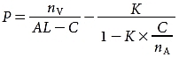
where
P = power of the target IOL (in diopters [D])
nV = index of refraction of the vitreous
AL = visual axial length (in millimeters)
C = ELP (in millimeters), the distance from the anterior corneal surface to the principal plane of the IOL
K = average dioptric power of the central cornea
nA = index of refraction of the aqueous
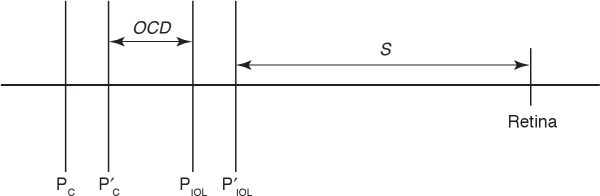
Figure 5-5 Schematic eye. PC and P′C are the front and back principal planes of the cornea, respectively. Similarly, PIOL and P′IOL are the front and back principal planes of the IOL. OCD = optical chapter depth; S = distance between back principal plane of the IOL and retina. (The drawing is not to scale.) (Redrawn by C. H. Wooley.)
Most of the advances in newer theoretical formulas (such as the Haigis, Hoffer Q, Hoffer H5, Holladay 1 and 2, Olsen, and SRK/T formulas) concerned improved methods of predicting the ELP, as described later in this chapter. These formulas are complex and cannot be used easily for calculation by hand. However, programmable calculators and applicable computer programs (eg, Hoffer Programs, Holladay IOL Consultant) are widely available, obviating this disadvantage. These formulas are also programmed into the IOLMaster, the Lenstar LS900 (discussed in the following section, “Biometric formula requirements”), and most modern ultrasonographic instruments, thereby eliminating any need for regression formulas. In all such cases, the surgeon must make sure that the formula author has verified the programming and accuracy of his or her particular formula.
Biometric formula requirements
Axial length The AL is the most important factor in these formulas. A 1-mm error in AL measurement results in a refractive error of approximately 2.35 D in a 23.5-mm eye. The refractive error declines to only 1.75 D/mm in a 30-mm eye but rises to 3.75 D/mm in a 20-mm eye. Therefore, accuracy in AL measurement is more important in short eyes than in long eyes.
ULTRASONIC MEASUREMENT OF AXIAL LENGTH When A-scan ultrasonography is used to measure AL, we either assume a constant ultrasound velocity through the entire eye or measure each of the various ocular structures at its individual velocity. A-scans measure not distance but rather the time required for a sound pulse to travel from the cornea to the retina. Sound travels faster through the crystalline lens and the cornea (1641 m/s) than it does through aqueous and vitreous (1532 m/s). Even within the lens itself, the speed of sound can vary in different layers of nuclear sclerosis. The measured sound transit time is converted to a distance by use of the formula
d = tV
where d is the distance in meters, t is the time in seconds, and V is the velocity in meters per second.
The average velocity through a phakic eye of normal length is 1555 m/s; however, it rises to 1560 m/s for a short (20-mm) eye and drops to 1550 m/s for a long (30-mm) eye. This variation is due to the presence of the crystalline lens; 1554 m/s is an accurate value for an aphakic eye of any length.
The following formula can be used to easily correct any AL measured with an incorrect average velocity:
where ALC is the AL value at the correct velocity, ALM is the resultant AL value at the incorrect velocity, VC is the correct velocity, and VM is the incorrect velocity.
In eyes with AL values greater than 25 mm, staphyloma should be suspected, especially when numerous disparate readings are obtained. Such errors occur because the macula is located either at the deepest part of the staphyloma or on the “side of the hill.” To measure such eyes and obtain the true measurement to the fovea, the clinician must use a B-scan technique. Optical methods (eg, IOLMaster, Lenstar) are very useful in such cases (see the following section).
When ultrasonography is used to measure the AL in biphakic eyes (ie, a phakic IOL in a phakic eye), it is difficult to eliminate the effect of the sound velocity through the phakic lens. To correct for this potential error, one can use the following published formula:
ALcorrected = AL1555 + C × T
where
AL1555 = the measured AL of the eye at a sound velocity of 1555 m/s
C = the material-specific correction factor, which is +0.42 for PMMA, –0.59 for silicone, +0.11 for collamer, and +0.23 for acrylic
T = the central thickness of the phakic IOL
Published tables list the central thickness of phakic IOLs available on the market (for each dioptric power). The least degree of error (in terms of AL error) is associated with use of a very thin myopic collamer lens, and the greatest amount of error is associated with use of a thick hyperopic silicone lens.
The 2 primary A-scan techniques—applanation (contact) and immersion (noncontact)—often give different results (Figs 5-6, 5-7). The applanation method may yield a shorter AL measurement that is also inconsistent and unpredictable. An artificially shortened AL measurement occurs with inadvertent corneal indentation. In the immersion method, which is accepted as the more accurate of the 2 techniques, space is maintained between the probe and the cornea, eliminating corneal indentation. See also Chapter 7 for more information on ultrasonography.
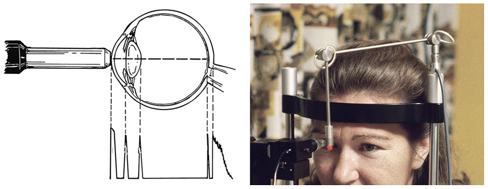
Figure 5-6 In applanation ultrasonography, the probe must contact the cornea, which causes corneal depression and shortening of the axial length reading. (Courtesy of Kenneth J. Hoffer, MD.)
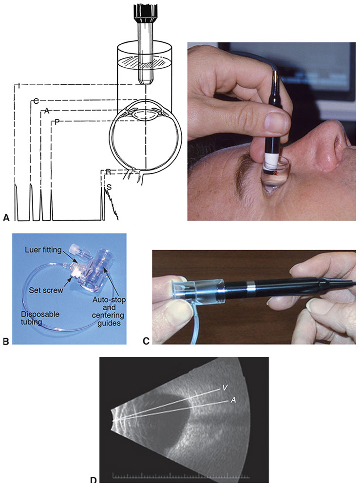
Figure 5-7 A, In immersion ultrasonography, the probe is immersed in the solution, placing it away from the cornea. B, Prager shell for immersion A-scan. C, Ultrasound probe and Kohn shell. D, B-scan of an eye with staphyloma, showing the difference between the anatomical length (A) and the visual length (V). (Courtesy of Kenneth J. Hoffer, MD.)
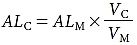
OPTICAL MEASUREMENT OF AXIAL LENGTH Another method of measuring AL was introduced in 1999. The IOLMaster (Zeiss-Meditec, Jena, Germany) uses a partial coherence laser for AL measurement (Fig 5-8). In 2008, a similar optical measuring device was introduced, the Lenstar LS900 (Haag-Streit, Köniz, Switzerland). In a manner analogous to ultrasonography, this device measures the time required for infrared light to travel to the retina. Because light travels at too high a speed to be measured directly, light interference methodology is used to determine the transit time and thus the AL. This technique does not require contact with the globe, so corneal compression artifacts are eliminated. This instrument was developed such that its readings would be equivalent to those of the immersion ultrasound technique. Because this device requires the patient to fixate on a target, the length measured is the path the light takes to the fovea: the “visual” AL. The ocular media must be clear enough to allow voluntary fixation and light transmission. Thus, in dense cataracts (especially posterior subcapsular cataracts), ultrasound biometry is still necessary (in 5%–8% of cataract patients). Compared with ultrasonography, this technique provides more accurate, reproducible AL measurements. In addition, optical measurement is ideal in 2 clinical situations that are difficult to achieve using ultrasonography: eyes with staphyloma and eyes filled with silicone oil.
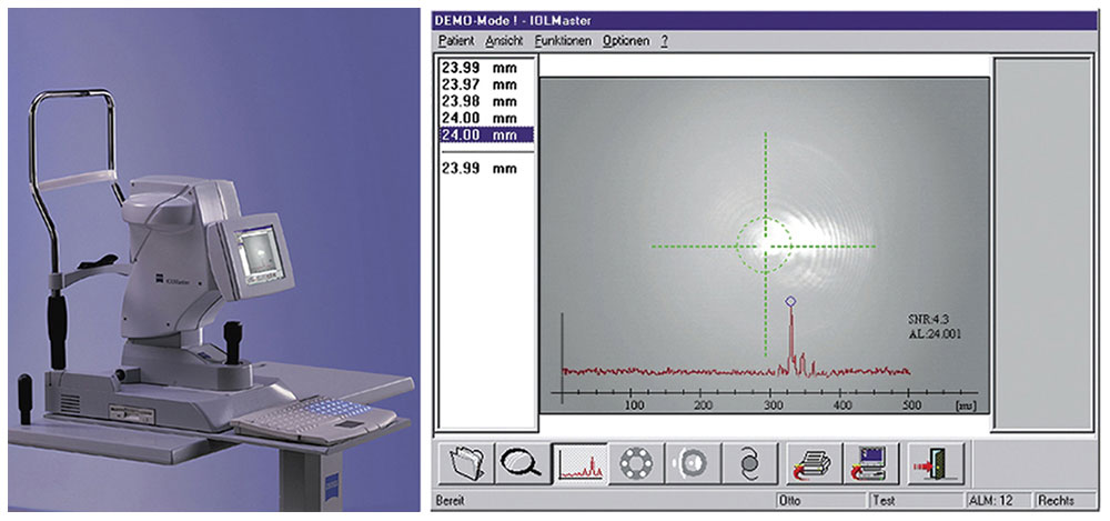
Figure 5-8 The IOLMaster (left) and view of the instrument’s axial length screen (right). (Courtesy of Kenneth J. Hoffer, MD.)
Corneal power The central corneal power, K, is the second most important factor in the calculation formula; a 1.0 D error in corneal power causes a 1.0 D postoperative refractive error. Corneal power can be estimated by keratometry or corneal topography, neither of which measures corneal power directly. The standard manual keratometer (Fig 5-9A) measures only a small central portion (3.2-mm diameter) of the cornea and views the cornea as a convex mirror. The corneal radius of curvature can be calculated from the size of the reflected image. Both front and back corneal surfaces contribute to corneal power, but the keratometer power “reading” is based on measurement of the radius of curvature of only the front surface and assumptions about the posterior surface.
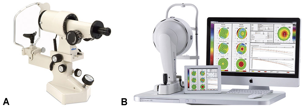
Figure 5-9 A, Manual keratometer. B, Oculus Pentacam. (Part A courtesy of Reichert Technologies; part B courtesy of Oculus Optikgeräte GmbH.)
The Pentacam (Oculus Optikgeräte GmbH, Wetzlar, Germany; Fig 5-9B) is a newer imaging system that uses a single Scheimpflug camera to measure the radius of curvature of the anterior and posterior corneal surfaces, as well as the corneal thickness, for the calculation of corneal power. Early studies have questioned the accuracy of the Pentacam in eyes that have undergone laser corneal refractive procedures. Newer software (2011) has made dramatic improvements. A later device, the Galilei (Ziemer Ophthalmic Systems AG, Port, Switzerland), measures corneal power by use of a dual Scheimpflug camera integrated with a Placido disk.
Estimated lens position All formulas require an estimation of the distance at which the principal plane of the IOL will be situated behind the cornea—a factor now known as the ELP. Initially, most IOLs were either anterior chamber (or prepupillary) IOLs. Thus, in the original theoretical formulas, this factor was called the anterior chamber depth (ACD), and it was a constant value (usually 2.8 or 3.5 mm). This value became incorporated in the A constant of the regression formulas of the 1980s.
In 1983, using pachymetry studies of posterior chamber IOLs as a basis, Hoffer introduced an ACD prediction formula for posterior chamber lenses that was based on the eye’s AL:
ACD = 2.93 × AL – 2.92
Other adjustments (second-generation formulas) were based on the AL. The Holladay 1 formula used the K reading and AL value as factors (in a corneal height formula by Fyodorov), as did the later SRK/T formula, whereas the Hoffer Q formula used the AL value and a tangent factor of K (all these formulas are third generation). Olsen added other measurements of the anterior segment, such as the preoperative ACD, lens thickness, and corneal diameter (this formula is fourth generation). Subsequently, Holladay used these factors, as well as patient age and preoperative refraction, in his Holladay 2 formula. Haigis eliminated K as a prediction factor and replaced it with the preoperative ACD measurement. These newer formulas are more accurate than those of the first and second generations, and all are currently in use.
The most accurate way to measure the preoperative ACD or the postoperative ELP is to use an optical pachymeter (Fig 5-10). Ultrasonography is usually less precise and provides a shorter reading. The IOLMaster is fairly accurate. The ACMaster (Zeiss-Meditec, Jena, Germany), based on the partial coherence interferometry technique, has recently been introduced.
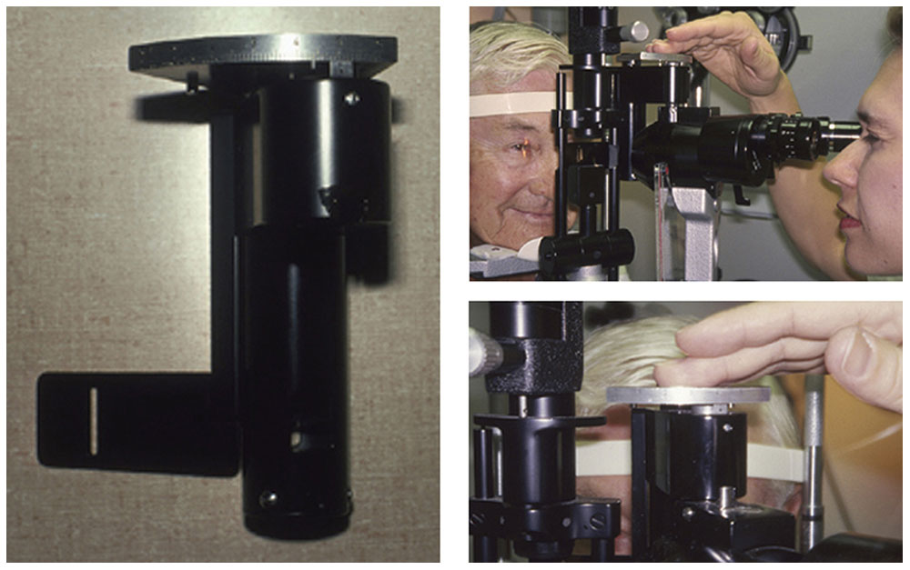
Figure 5-10 An optical pachymeter mounted on a slit lamp. (Courtesy of Kenneth J. Hoffer, MD.)
Most formulas use only one constant, such as the ACD, the A constant, or the surgeon factor (SF). One exception is the Haigis formula, which uses 3 constants (a0, a1, a2). The A constant, developed as a result of regression formulas, was widely used in the 1980s, so much so that manufacturers assigned each lens design a specific A constant, as well as an ACD value. Even though regression formulas (eg, SRK formula) are no longer recommended and rarely used for IOL calculation, the A constant still exists for the SRK/T formula.
Holladay developed 2 formulas that convert a lens’s A constant to another factor. The first converts the A constant to an SF for the Holladay formula:
SF = (0.5663 × A) – 65.6
where A is the IOL-specific A constant and SF is the Holladay surgeon factor. The second formula converts a lens’s A constant to a personalized ACD (pACD) for the Hoffer Q formula:
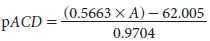
where A is the IOL-specific A constant and pACD is the Hoffer pACD (ELP). So, for example, an A constant of 113.78, 116.35, or 118.92 converts to a pACD of 2.50 mm, 4.00 mm, or 5.50 mm, respectively.
It is prudent to calculate the power of an alternate IOL before surgery. If not calculated in advance, the power of an IOL intended for bag placement can be decreased for sulcus placement with subtraction of 0.75–1.50 D, depending on the AL value.
Formula choice
Several studies have indicated that the Hoffer Q formula is more accurate for eyes shorter than 24.5 mm; the Holladay 1, for eyes ranging from 24.5 to 26.0 mm; and the SRK/T, for eyes longer than 26.0 mm (very long eyes). A recent (2011) study conducted in the United Kingdom proved the statistical significance of these recommendations in more than 8000 eyes by use of optical AL values. For long eyes, the Haigis formula may achieve equivalent results.
The choice of formula is, of course, up to the surgeon, but whatever the method, every effort should be made to ensure that the biometry is as accurate as possible. The operating surgeon should review preoperative AL values and K readings. If a reading is suspect because it lies outside normal limits, biometry should be repeated during or immediately after the initial reading. Similarly, it is prudent to measure both eyes and recheck the readings if there is a large discrepancy between the 2 eyes. Great care should be taken in the measurement of eyes that have undergone previous refractive surgery (corneal or phakic IOL), as well as those that have undergone an encircling band treatment of a retinal detachment.
Piggyback and Supplemental Intraocular Lenses
When an IOL is inserted into an eye that already has an IOL, the second IOL is called a piggyback IOL. The piggyback IOL can be inserted at the time the first IOL is implanted to produce a high power that is commercially unavailable. It can also be inserted secondarily to correct a postoperative refractive error. Computer programs can be used to calculate the power of the second IOL and to make adjustments, which may be needed if the posterior IOL is displaced posteriorly. However, these adjustments are minor, and using one of the following formulas is the easiest way to calculate them:
Myopic correction: P = 1.0 × error
Hyperopic correction: P = 1.5 × error
Stay updated, free articles. Join our Telegram channel

Full access? Get Clinical Tree


