Figure 7-1 A plus lens used to view an object positioned in the focal plane of the lens. O = object; f = focal length. (Redrawn from Basic and Clinical Science Course Section 2: Optics, Refraction, and Contact Lenses. San Francisco: American Academy of Ophthalmology; 1986–1987:73. Fig 43.)
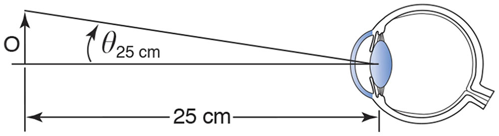
Figure 7-2 The reference viewing distance of 25 cm, used in the definition of magnification of simple magnifiers. (Redrawn from Basic and Clinical Science Course Section 2: Optics, Refraction, and Contact Lenses. San Francisco: American Academy of Ophthalmology; 1986–1987:73. Fig 44.)
Telescopes
A telescope is an optical system designed to increase the angle subtended at the eye by distant objects. It is called afocal because pencils of light entering with zero vergence come out with zero vergence. The first lens, the objective, forms an image of the distant object. The second lens, the eyepiece or ocular, is then used to view the image formed by the objective. With small-angle approximations, a telescope’s angular magnification (or “minification,” if you look through the telescope turned the other way around) is the longer focal length of the objective divided by the shorter focal length of the ocular, with a minus sign to enable us to figure out whether the final image is upright or inverted:
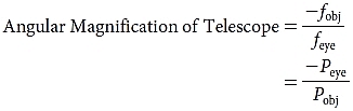
where
fobj = focal length of objective
feye = focal length of eyepiece
Peye = power of eyepiece
Pobj = power of objective
Galilean Telescope
In a Galilean telescope, the objective is a plus lens, and the eyepiece is a minus lens. Bundles of rays with approximately zero vergence, emanating from various points on a distant object, pass through a low-power plus objective lens. Before the rays are able to arrive to focus at the secondary focal point of the first lens, they meet a higher-power minus lens, the eyepiece, which has been placed so that its primary focal point coincides with the secondary focal point of the first lens. Thus, the rays leave the second lens with no vergence, and the telescope is therefore said to be afocal (Fig 7-3). The image is magnified and upright.
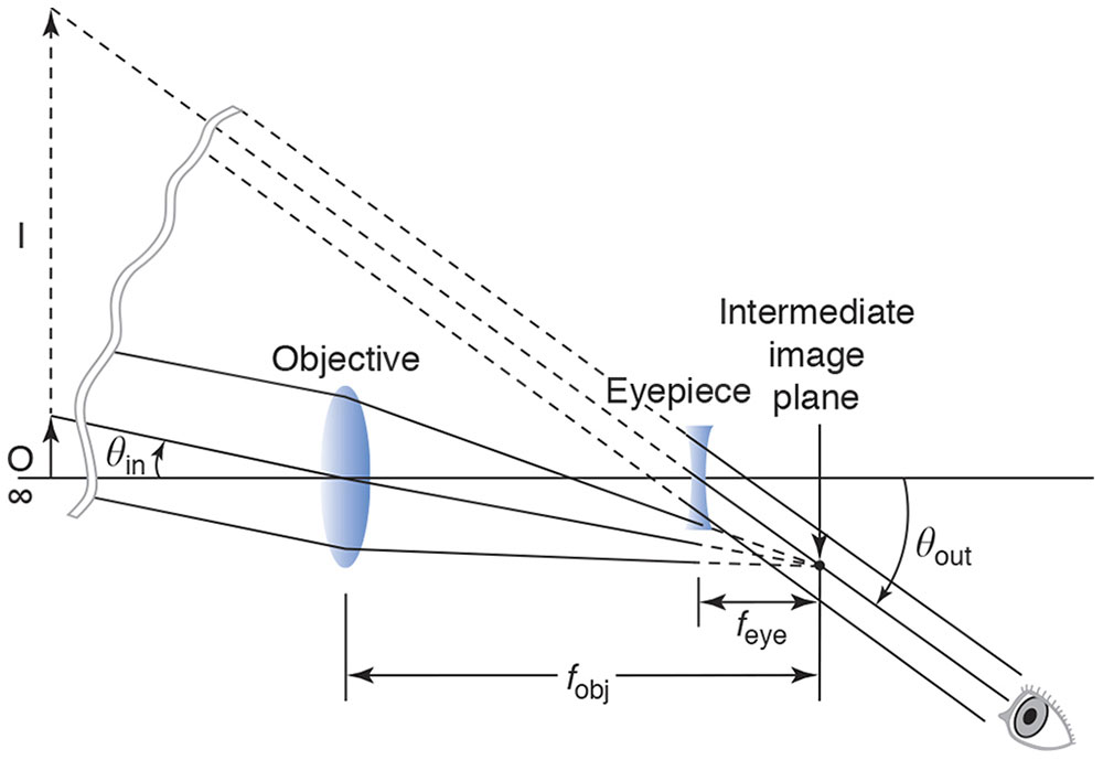
Figure 7-3 Galilean telescope. (Redrawn from Guyton D, West C, Miller J, Wisnicki H. Ophthalmic Optics and Clinical Refraction. London: Prism Press;1999:39.)
The distance separating the eyepiece from the objective, which is the length of the telescope, equals the difference between the focal lengths of the objective and the eyepiece.
Astronomical Telescope
In an astronomical, or Keplerian, telescope, both the objective and the eyepiece are plus lenses. Light without vergence enters a low-power objective lens, just as in the Galilean telescope. Whereas in the Galilean telescope a minus lens is placed in the path before the light reaches its secondary focal point, in the astronomical telescope a stronger, convex lens is placed beyond the secondary focal point of the first convex lens, with its primary focal point coinciding with the secondary focal point of the first lens. The distance separating the eyepiece from the objective is the sum of the focal lengths of the objective and the eyepiece. Once again, we have an afocal system; rays that enter with zero vergence exit with zero vergence. A large low-power objective lens collects relatively large-angle pencils of light from a distant object; in particular, it collects more of the light coming from that object than would enter the viewer’s smaller entrance pupil without the telescope (Fig 7-4).
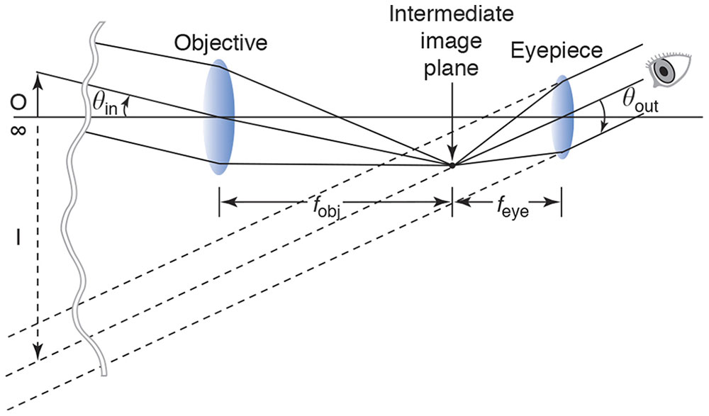
Figure 7-4 Astronomical telescope. (Redrawn from Guyton D, West C, Miller J, Wisnicki H. Ophthalmic Optics and Clinical Refraction. London: Prism Press; 1999:39.)
The image seen through the astronomical telescope is inverted as well as magnified. If we wish to render the image upright, we must invert it again by passing the light path through at least one more lens or through a set of internally reflecting prisms such as those inside typical binoculars. Because they “fold” the light path, the prisms used in binoculars also enable the binoculars to be more compact and to have the right and left objective lenses spread farther apart than the viewer’s eyes, enhancing the perception of depth. Note that the minus sign in the formula for the telescope’s angular magnification yields, as it should, a positive power for the Galilean telescope’s upright image and a negative power for the astronomical telescope’s inverted image.
Accommodation Through a Telescope
If you look at an object one-third of a meter away, your otherwise emmetropic eye must accommodate 3 diopters. If you look at the same object one-third of a meter away through an afocal telescope, you have to accommodate much more: the accommodation required through the telescope is the usual amount, 3 D, multiplied by the square of the magnification of the telescope. For instance, the accommodation required through a 2× telescope would be 3 × (2)2 = 12 D, which is too difficult for an adult to achieve. Therefore, in order to enable us to see near objects through a telescope, we need to alter the telescope, in the manner we next describe, to form a loupe.
Surgical Loupe
We can make an afocal telescope into a surgical loupe with a working distance of one-third meter by adding a +3 D lens to the front of the telescope. The +3 D lens is called a collimating lens because its purpose is to redirect the rays of pencils of light diverging from an object one-third of a meter away so that they have zero vergence, before they enter the telescope. Because the telescope is afocal, the pencils of light will have zero vergence again when they exit the telescope, and a surgeon with emmetropic vision can effortlessly view the object and see it as larger, thanks to the angular magnification. The +3 D additional power can be added to the power of the objective lens instead of adding an additional lens in front of the afocal telescope (Fig 7-5).
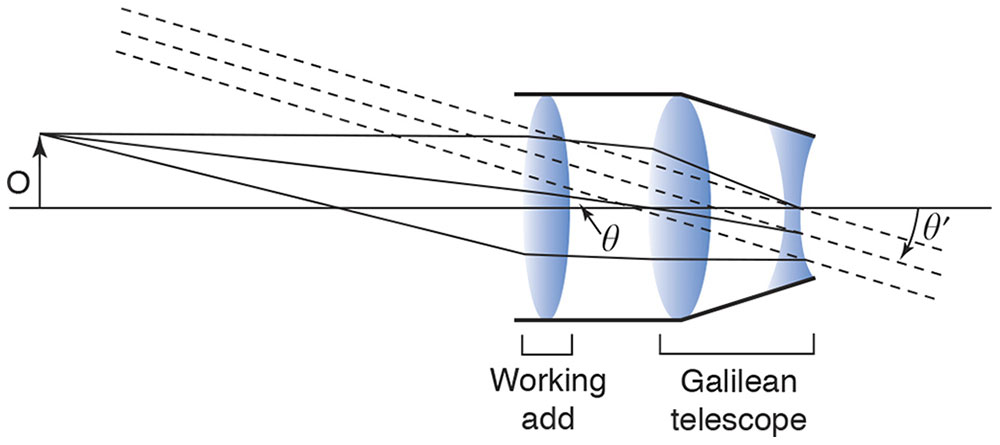
Figure 7-5 The surgical loupe. The working add first collimates the light from the tip of the object, O. This bundle of collimated light enters the Galilean telescope at a particular angle, θ, to the optical axis. The same bundle emerges from the telescope still collimated but at an increased angle, θ′, where the magnifying power of the telescope is equal to the ratio of θ′ to θ. The tip of the object is seen by the eye as if it were at infinity, with the entire object subtending the angle θ′. (Redrawn from Basic and Clinical Science Course Section 2: Optics, Refraction, and Contact Lenses. San Francisco: American Academy of Ophthalmology; 1986–1987:74. Fig 45.)
General Principles of Optical Engineering
More-elaborate designs of telescopes and microscopes use additional lenses, perhaps aspheric, to adjust the distance to the object (working distance) and combat the blurring caused by monochromatic and chromatic aberrations and diffraction. Apertures and antireflective lens coatings serve to eliminate undesirable rays.
Terminology
This section introduces some terminology you are likely to encounter elsewhere.
The aperture stop of an optical system is the opening—which could be the rim of one of its lenses or an empty diaphragm—whose edges limit the angular breadth of the pencils of light that are allowed to pass through the system to form the image of an object. For instance, the pupil of the eye serves as its aperture stop and opens in dim conditions to allow broader pencils of light to enter.
The field of view of a multi-element optical system is the visible extent of the image plane. For example, a typical pair of binoculars might have a field of view of 7 degrees—objects outside that field cannot be seen without turning the binoculars toward them. When a 2× condensing lens is used with the indirect ophthalmoscope, the field of view is 2 times larger in degrees than with a 4× condensing lens of the same diameter. Twice the diameter of the field viewed gives 4 times as much area.
When you look at someone’s pupil through the cornea and aqueous, the pupil appears to be larger and closer than it truly is. What you are seeing is the entrance pupil of the eye’s optical system—the image of the eye’s aperture stop, the pupil, viewed through the optical elements that precede it in the system. Rays that do not pass through the eye’s entrance pupil cannot reach the retina because they are unable to pass the aperture stop, which is the pupil of the eye.
For an observer to see the entire field of view of an optical instrument, his or her entrance pupil needs to be located at the instrument’s exit pupil, which is the image of its aperture stop formed by the optical elements following it in the system. The distance from the last surface of the eyepiece to that exit pupil is called the eye relief of the instrument.
In the preceding section, we discussed the adjustment of working distance to form a loupe. Suppose an object is well focused on the loupe’s image plane; how much closer or farther away can we move the object without noticeable blurring of the image? The distance the object can be moved is the system’s depth of field. Depth of focus, on the other hand, is the amount of leeway on the image side of the system; for example, it refers to how near or far you can move a screen relative to a focused projector before the image becomes noticeably out of focus.
Measurements of Performance of Optical Systems
The f-stop of a lens, familiar to photographers, and a related concept, the numerical aperture, are measures of light gathering. Light gathering is important not only in generating a bright image of a dim source; it is also related to the resolving power of an instrument—how close together 2 points can be on an object before they become indistinguishable in the image. If a higher-power instrument does not take in a wide-angled pencil of light from each of the 2 nearby points, no matter how carefully the instrument is constructed, the diffraction patterns coming from the 2 points will overlap too much to be distinguished from each other. For example, the oil immersion objective of a microscope has a higher numerical aperture than a dry objective, which means that it can gather a wider angle of light from each point source and therefore have the potential for better resolution.
Light beginning at a point source and passing through a focused optical system does not all focus to the same image point because of aberrations and diffraction. The spread-out luminance that is detected is called the point spread function. The modulation transfer function (MTF) of an optical system is a measure of its ability to preserve an object’s contrast, such as that of a sinusoidal pattern of light and dark, in the image that comes out of the system. This ability varies with the spatial frequency of the pattern being imaged, and the MTF helps a designer choose the best optical elements for the purpose at hand.
Optical Instruments and Techniques Used in Ophthalmic Practice
Direct Ophthalmoscope
Suppose you want to look at my retina and that we both have eyes that are emmetropic and not accommodating. A pencil of rays coming from a point on my retina leaves my eye with zero vergence, and the pencil continues to have no vergence until it reaches your eye, which focuses it exactly on your retina. When you look through the peephole of a direct ophthalmoscope with no lenses in place, just past the edge of a mirror that reflects light into my eye, almost coaxial to your view, you will see an upright, virtual, magnified image of a small portion of my retina; our retinas are on conjugate planes. The optics of the eye are approximately +60 D, so the magnification is 60/4, or 15×, as we have defined magnification for a simple magnifier. In case either of us has an uncorrected spherical refractive error, a wheel of spherical lenses is available to dial into the path. If the subject eye is myopic, the extra plus power of the eye’s optics and the minus power dialed into place in the ophthalmoscope together form a Galilean telescope, increasing magnification and decreasing the field of view. Similarly, the retina of a hyperopic eye will be magnified less than 15× because of the reverse Galilean telescope created by the optics of the eye and the lens of the direct ophthalmoscope. A retinal lesion elevated 1 mm will be approximately 3 D out of focus when viewed with the direct ophthalmoscope (Fig 7-6).
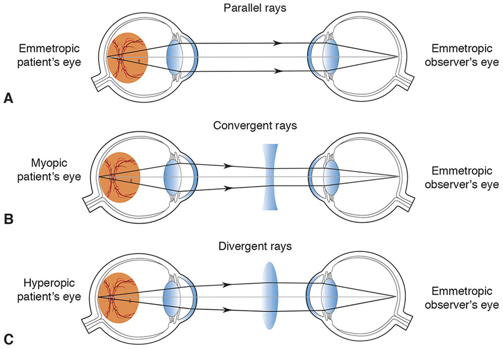
Figure 7-6 Viewing system of a direct ophthalmoscope. A, A bundle of light rays emerges from the emmetropic eye with zero vergence. B, A bundle of light rays emerges converging from the myopic eye with positive vergence; the corrective lens is minus. C, A bundle of rays with negative vergence diverges coming out of the hyperopic eye; the corrective lens is plus. (Developed by Neal H. Atebara, MD. Redrawn by C. H. Wooley.)
Indirect Ophthalmoscope
In an indirect ophthalmoscope, mirrors direct a bright light toward the subject’s retina through, for instance, a 20 D lens and the subject’s eye. The lens has an aspheric design on one side and antireflective coatings to minimize aberrations and glare. Assuming that the subject eye is emmetropic, a pencil of light coming from an illuminated point on the retina leaves the eye with zero vergence (Fig 7-7A). The pencil of light is gathered and refracted by the large +20 D “condensing” lens to focus to a point one-twentieth of a meter (5 cm) closer to the observer, who therefore sees an optically real, inverted aerial image of the retina that appears to be 5 cm closer to her eye than the 20 D lens in her hand (Fig 7-7B). If the aerial image is 50 cm from her eye, she will have to accommodate 2 D to see it, so a 2 D lens is added on the front of the ophthalmoscope (Fig 7-8).
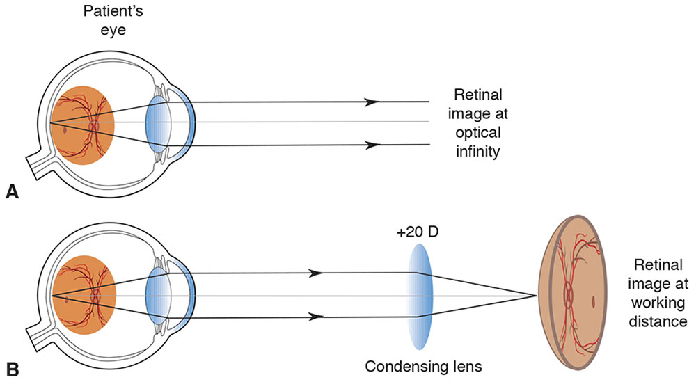
Figure 7-7 Fundus image formation. A, A retinal image is formed at optical infinity. B, A condensing lens focuses a bundle of parallel rays to a place closer to the viewer than his or her hand. (Developed by Neal H. Atebara, MD. Redrawn by C. H. Wooley.)
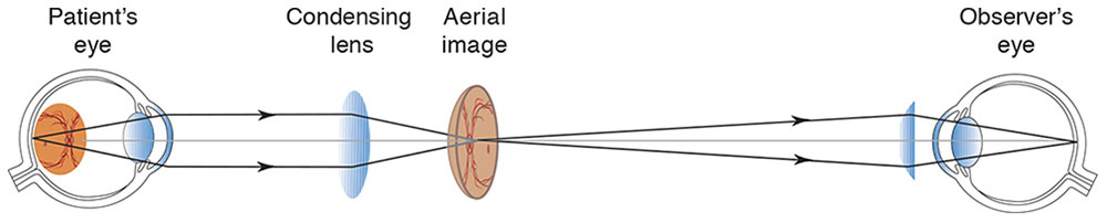
Figure 7-8 The “aerial” image. The light rays focus and diverge, and they are brought to a new focus on the observer’s retina by a condensing lens and the optics of the observer’s eye. (Developed by Neal H. Atebara, MD. Redrawn by C. H. Wooley.)
Mirrors are used in the binocular instrument to bring an image to each of the observer’s eyes, adjusting as needed for the observer’s interpupillary distance. To avoid glare, it is important that the observer’s pupils be conjugate with the pupil of the patient’s eye, so that the illuminating and 2 viewing paths pass through the pupils of both people (Figs 7-9, 7-10). If the patient’s pupil is small, the ingoing path and the 2 outgoing paths can be brought closer by varying the positions of mirrors (Fig 7-11).
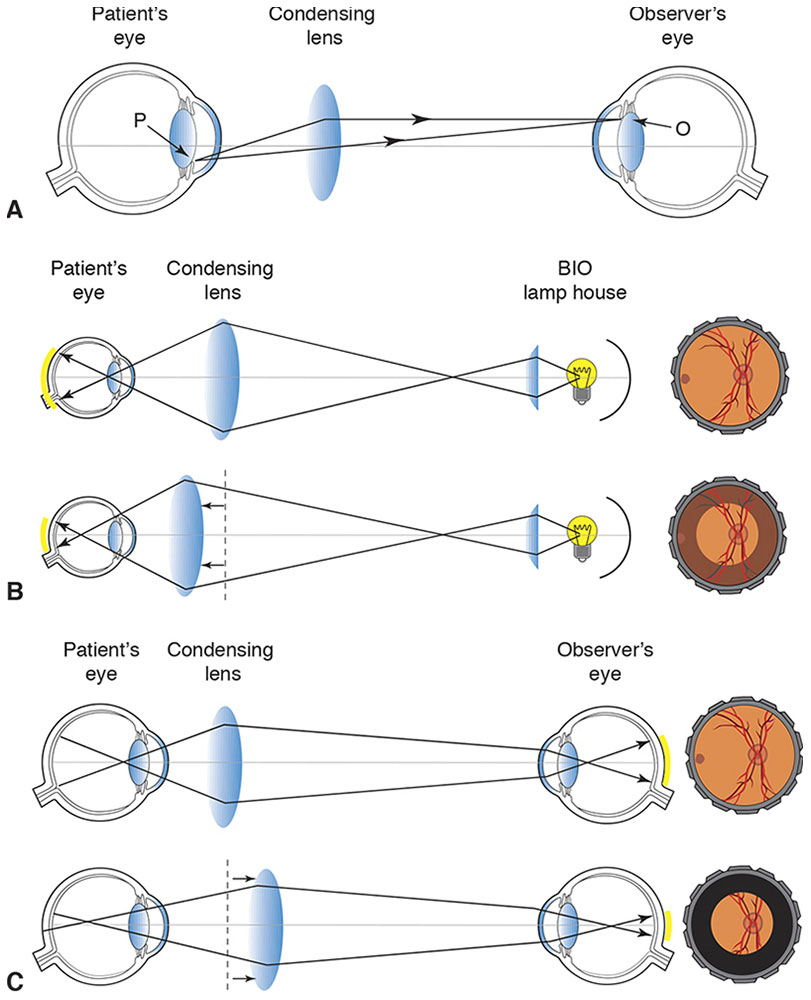
Figure 7-9 Conjugacy of pupils. A, In indirect ophthalmoscopy, the observer’s pupil (O) and patient’s pupil (P) are conjugate to avoid “wasting” light. B, If the condensing lens is too close to the patient’s eye, the peripheral retina will not be illuminated. C, If the condensing lens is too far from the patient’s eye, light from the patient’s peripheral retina will not reach the observer’s eye. (Developed by Neal H. Atebara, MD. Redrawn by C. H. Wooley.)
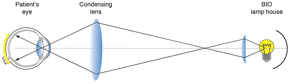
Figure 7-10 Indirect ophthalmoscope: illumination. (Developed by Neal H. Atebara, MD. Redrawn by C. H. Wooley.)
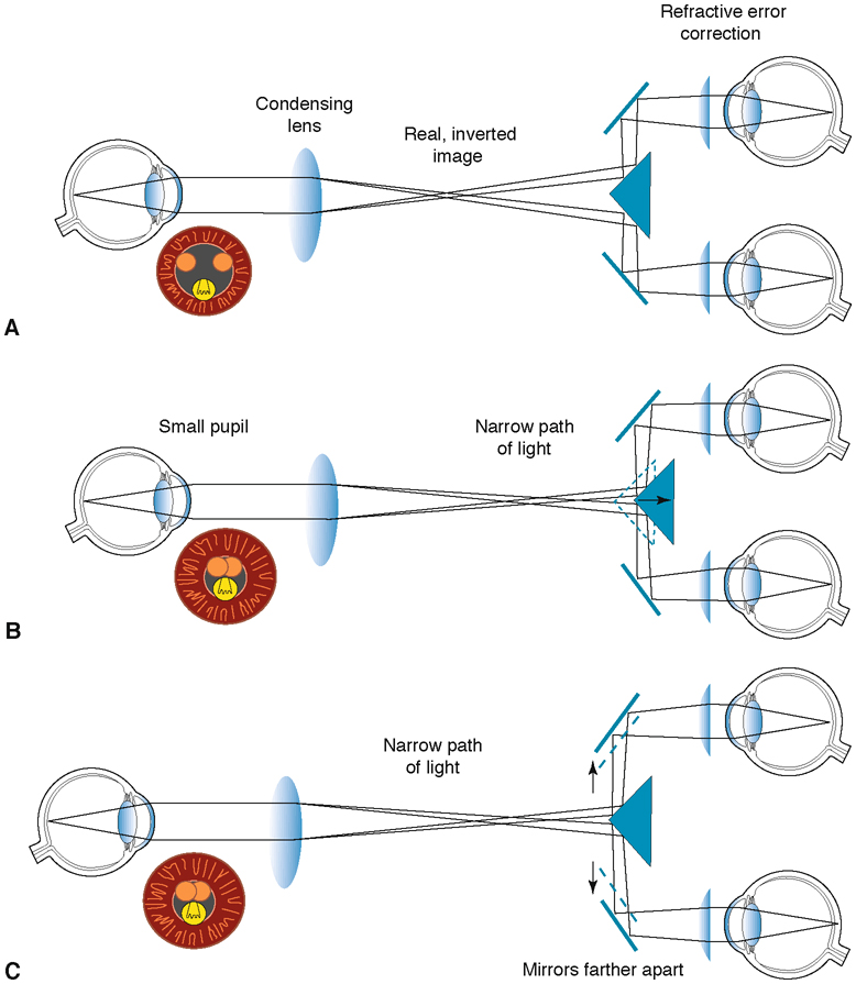
Figure 7-11 Indirect ophthalmoscope: mirrors used for binocular viewing. A, Binocular observation. B, To achieve binocularity when viewing through a small pupil, one can bring the light paths closer together by moving the triangular mirror closer to the observer. C, Alternatively, when viewing through a patient’s small pupil, one can bring the light paths closer together by moving the eyepieces as far apart as the observer’s interpupillary distance allows, or by moving the observer’s head farther from the patient. Orange circles represent viewing paths, and yellow circles represent illumination paths in the black pupil. (Developed by Neal H. Atebara, MD. Redrawn by C. H. Wooley.)
This procedure can be conceived of as the observer viewing the retina through an astronomical telescope consisting of the 60 D optics of the patient’s eye, which acts as the objective lens, and the 20 D lens held in the observer’s hand, which acts as the eyepiece. In this case, the transverse magnification of the telescope would be 60/20 = 3×, and the axial magnification 9×.
The exaggerated depth is quartered by the mirrors, because they reduce the effective interpupillary distance from 60 mm to 15 mm, so the perception of axial magnification is only about 9/4. Condensing lenses of various powers may be used. For example, a +30 D lens would give 2× transverse and 1× axial magnification, resulting in retinal features looking smaller and flatter and giving a larger field of view than that provided by the 20 D lens. Are the objects and images in this situation real or virtual? Rays reaching the observer’s eye come from an “object” to the left of the direct ophthalmoscope’s optics, so we consider that a “real” object. The indirect ophthalmoscope focuses a real image in the air to the right of itself, and the observer sees that aerial, real, inverted image with the assistance of a simple magnifier.
Fundus Camera
A fundus camera is nearly identical to the indirect ophthalmoscope; the aerial image is simply reimaged onto the camera’s film or sensor array (Figs 7-12, 7-13).
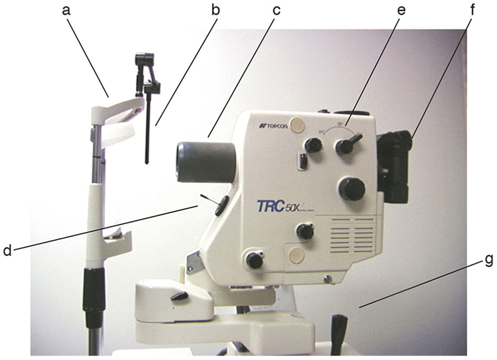
Figure 7-12 Photograph of a fundus and fluorescein angiography camera showing patient forehead rest (a), fixation light (b), objective lens (c), fixation pointer (d), magnification lever (e), camera housing and eyepiece (f), and joystick (g). (Courtesy of Neal H. Atebara, MD.)
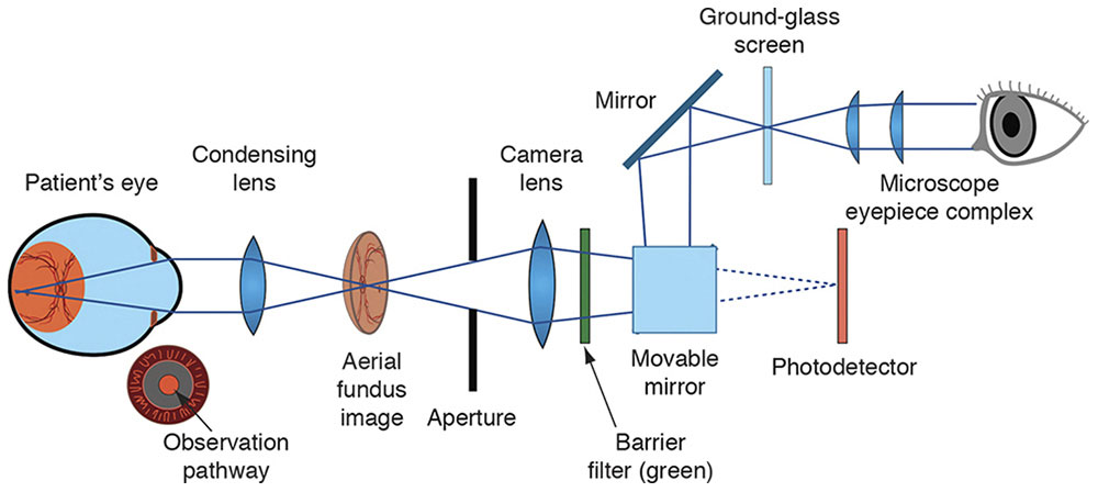
Figure 7-13 Observation system of a fundus camera. As in the observation system of an indirect ophthalmoscope, the condensing lens takes light rays from the illuminated fundus and creates an “aerial” image. A conventional single-lens reflex camera body, with its microscope eyepiece and ground-glass screen, is then used to focus on the aerial image. When the photograph is taken, a movable mirror flips up, exposing the film or photodetector. (Courtesy of Neal H. Atebara, MD. Redrawn by C. H. Wooley.)
Slit-Lamp Biomicroscope
In a slit-lamp biomicroscope, a system of lenses and apertures (known as Koehler illumination) is designed to collect the light from the device’s bulb into a beam of homogeneous brightness, giving good contrast and minimal glare. The beam, limited by an adjustable slit to cut an optical section through the eye, can be rotated horizontally around the eye, as can the binocular microscope. The illuminating system and the microscope with its various levels of magnification are designed to be parfocal—the position of the slit lamp with respect to the eye being examined does not need to be changed as the power of the microscope is changed and the lamp and microscope are rotated around the eye.
Let’s follow the outgoing light path. A pencil of rays diverging from the subject eye passes through a collimating lens so that its rays emerge parallel to each other before passing through an afocal Galilean telescope. Mirrors of internally reflecting prisms invert the image and reflect it into the eyepiece. The eyepiece is an astronomical telescope, which re-inverts the image. To vary the magnification of the system, there may be a rotating drum of Galilean telescopes that can be oriented either forward to provide higher magnification or backward to provide lower magnification, or there may be 2 sets of eyepieces. Another drum may enable the viewer, as with some indirect ophthalmoscopes, to choose a narrower angle between the microscope’s 2 light paths, enabling a binocular view through a small pupil (Fig 7-14).
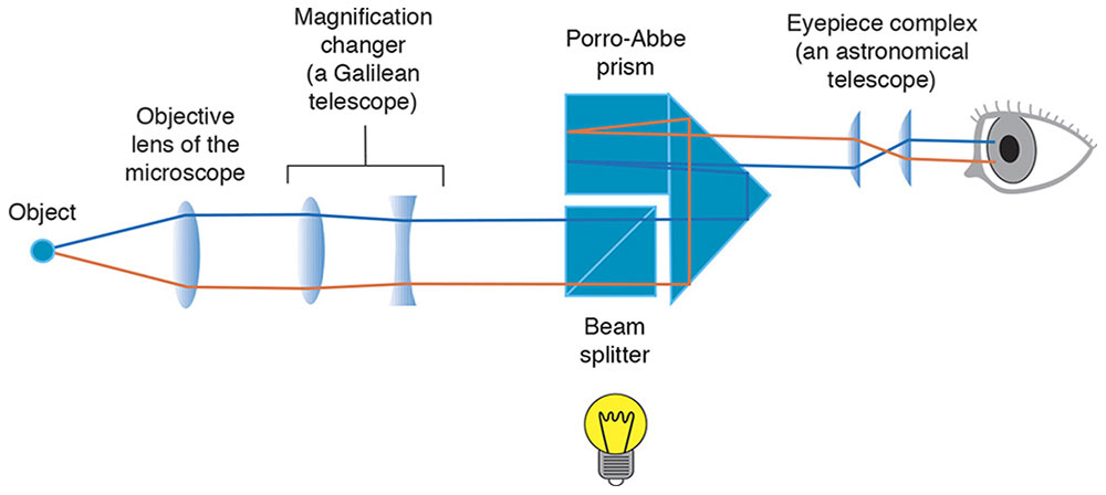
Figure 7-14 Slit-lamp biomicroscope. (Developed by Neal H. Atebara, MD. Redrawn by C. H. Wooley.)
Features of the eye are examined in several ways (Fig 7-15):
- Direct illumination. Light is reflected from the object to the observer.
- Retroillumination. Light bouncing back toward the viewer silhouettes features, such as a cataract.
- Sclerotic scatter. The illumination is turned to shine a slit beam at the limbus, enabling the observer to look at the central cornea for features highlighted by the internally reflected light.
- Specular reflection. The corneal endothelial cell pattern can be seen by examining the partial specular reflection from the cornea–aqueous interface as a slit beam strikes it at an angle.
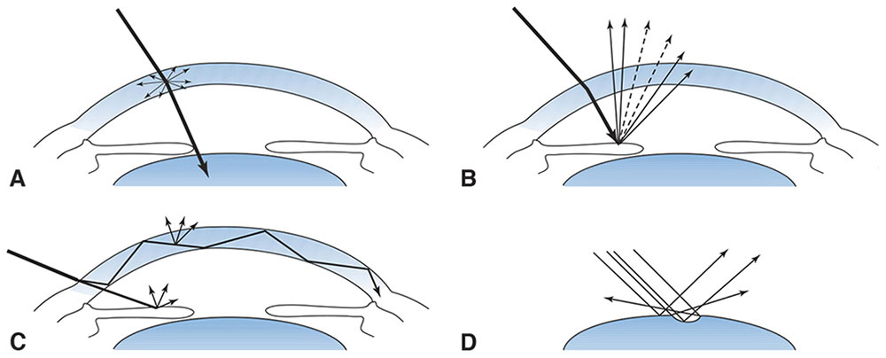
Figure 7-15 Diagram of how light rays interact with the eye in the 4 forms of slit-lamp biomicroscopic examination. A, Direct illumination. B, Retroillumination. C, Sclerotic scatter. D, Specular reflection. (From Tasman W, Jaeger AE, eds. The slit lamp: history, principles, and practice. In: Duane’s Clinical Ophthalmology. Philadelphia: Lippincott, 1995–1999:33. Redrawn by C. H. Wooley.)
Auxiliary lenses for slit-lamp examination of the retina
The cornea and lens together provide so much convergence that we cannot look through them with the slit lamp and see the retina. We can overcome this problem by eliminating the corneal curvature with a flat-front contact lens (Fig 7-16). Mirrors inside such a lens provide views of more and less posterior portions of the eye (Fig 7-17). A high-minus (Hruby –55 D) lens is positioned in the air in front of the cornea (Fig 7-18) and yields a view that is not inverted. Indirect ophthalmoscopy at the slit lamp is accomplished either by holding a high-plus lens in front of the cornea to produce an inverted, aerial, real image (Fig 7-19) or by placing a panfundoscopic contact lens on the cornea (Fig 7-20), which produces an inverted, real image inside itself. Aspheric lenses are designed to minimize aberrations for their specific uses.
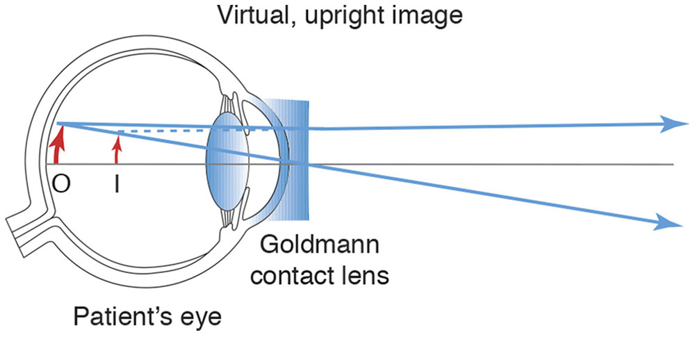
Figure 7-16 A Goldmann flat-front contact lens eliminates the corneal curvature. I = image; O = object. (Developed by Neal H. Atebara, MD. Redrawn by C. H. Wooley.)
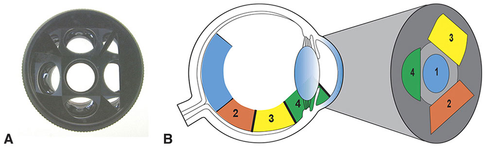
Figure 7-17 Mirrors at various angles inside a flat-front contact lens for viewing different parts of the retina and the anterior chamber angle. A, Goldmann 3-mirror contact lens (observer’s view). B, Schematic diagram of the part of the eye that can be seen with the central contact lens (1), midperipheral fundus mirror (2), peripheral fundus mirror (3), and iridocorneal angle mirror (4). (Both parts courtesy of Neal H. Atebara, MD. Part B redrawn by C. H. Wooley.)
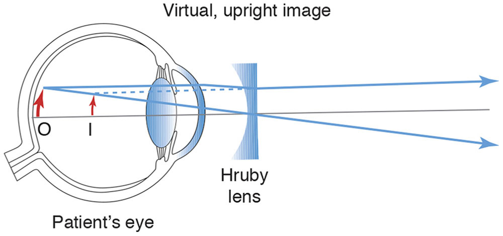
Figure 7-18 A high-minus noncontact (Hruby) lens overcomes the power of the cornea. I = image; O = object. (Developed by Neal H. Atebara, MD. Redrawn by C. H. Wooley.)
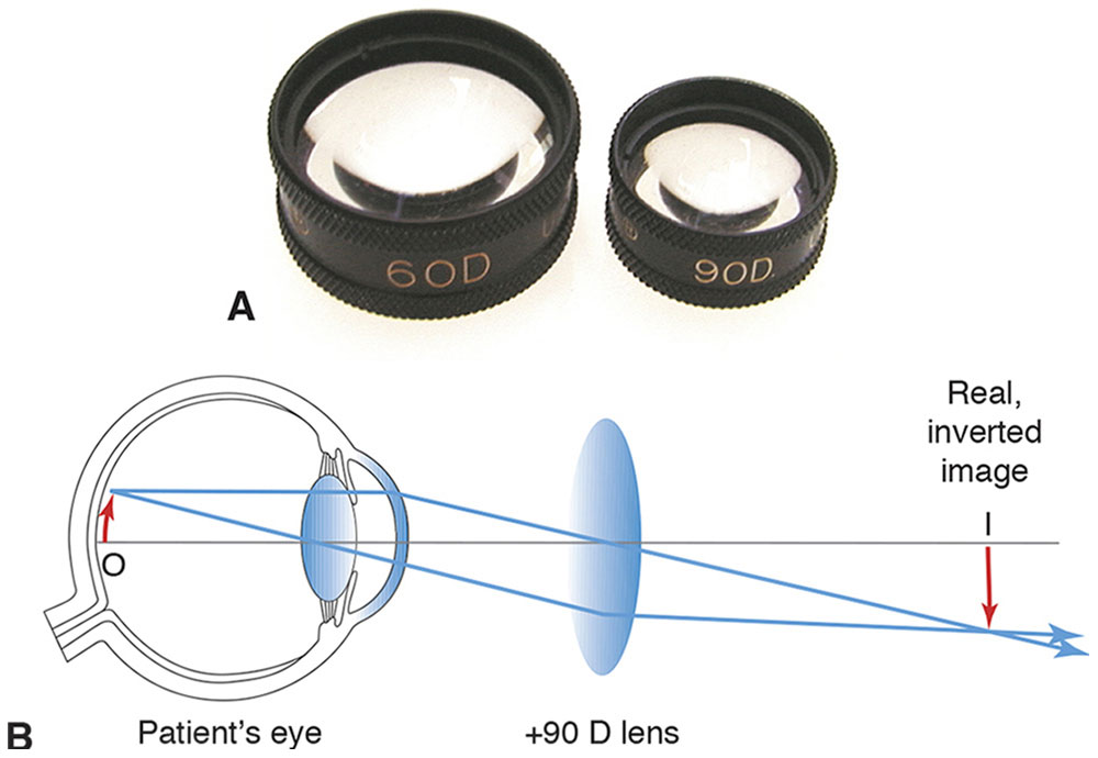
Figure 7-19 High-power plus lenses for slit-lamp indirect ophthalmoscopy. A, 60 D and 90 D fundus lenses. B, The lenses produce real, inverted images of the retina within the focal range of a slit-lamp biomicroscope. I = image; O = object. (Both parts courtesy of Neal H. Atebara, MD. Part B redrawn by C. H. Wooley.)
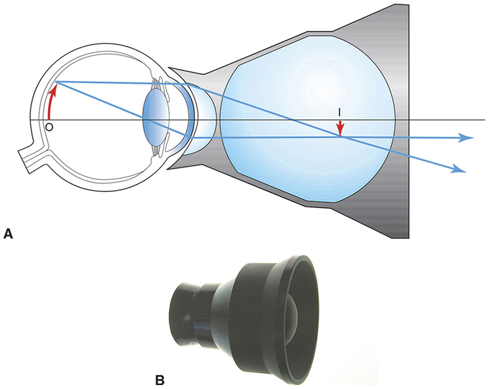
Figure 7-20 A, A panfundoscope lens consists of a corneal contact lens and a high-power, spherical condensing lens. A real, inverted image of the fundus is formed within the spherical glass element, which is within the focal range of a slit-lamp biomicroscope. I = image; O = object. B, Photograph of the panfundoscope lens. (Both parts courtesy of Neal H. Atebara, MD. Part A redrawn by C. H. Wooley.)
Gonioscopy
Unless a gonioscopy lens is placed on the eye, the anterior chamber angle is hidden from view by total internal reflection (TIR; see Chapter 1). This problem is solved by use of a contact lens with a mirror or a contact lens allowing direct viewing at an angle less than the critical angle (Fig 7-21).
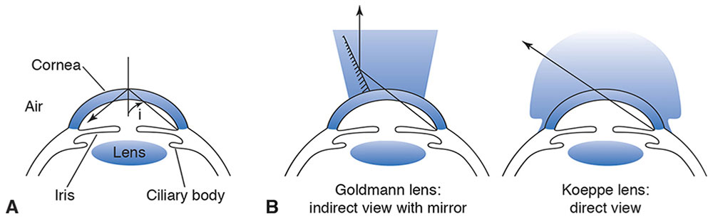
Figure 7-21 Gonioscopy. A, At the anterior corneal surface, rays from the anterior chamber angle are incident at greater than the critical angle of cornea in air. Therefore, these rays are totally internally reflected. B, The contact lens curvature approximately matches the cornea, the space between the lens and the cornea being filled with an aqueous solution of methylcellulose or with tears, which have a refractive index close to that of the cornea. Light can then traverse the interface with little lost to reflection, as the critical angle at the interface is now nearly 90°. On the left is a contact lens with an internal mirror, reflecting the image toward the observer. On the right is the Koeppe lens, which gives a direct rather than reflected view of the anterior chamber. (Illustration by C. H. Wooley.)
Surgical Microscope
The viewing optics of an operating microscope are similar to those of the slit lamp. The illumination is “coaxial,” running near the viewing paths.
Geneva Lens Clock
The Geneva lens clock uses 3 pins to measure the curvature of a spectacle lens. It is calibrated for a specific refractive index (usually crown glass, n = 1.53), so the actual power reading will be incorrect for lenses made of other materials. For these lenses, the instrument is still useful to determine if there is front or back ground cylinder or if the lens is warped (Fig 7-22).
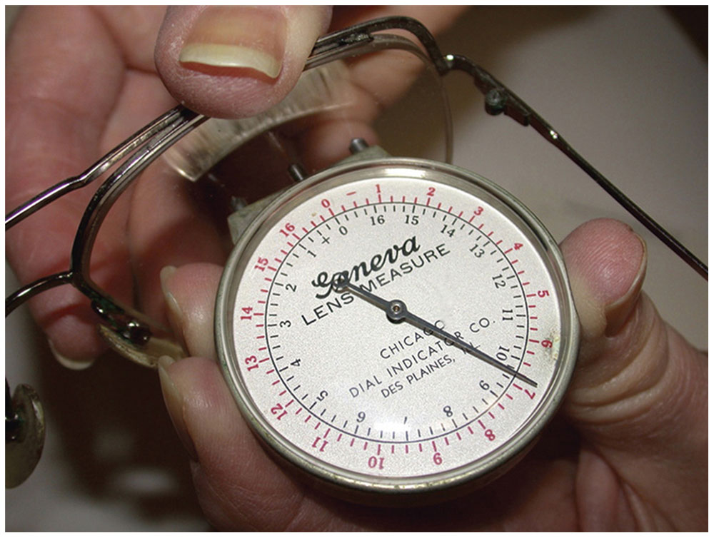
Figure 7-22 Geneva lens clock. Only the middle pin moves, measuring the curvature. (Courtesy of Tommy S. Korn, MD.)
Lensmeter
To measure the power of a lens using a lensmeter, we place the lens on a nose cone at the top of a cylinder. Farther down, a convex lens is fixed in place such that its secondary focal point is just at the posterior vertex of the lens being measured. Still farther down the tube is a movable illuminated target; when the dial of the lensmeter reads 0, the target is at the primary focal point of the fixed lens. If the lens being measured has no power, then parallel rays arrive at the eyepiece, which is an astronomical telescope, and the target appears well focused to the emmetropic nonaccommodating observer. If the lens has power, the target is moved until it appears in focus, and the power of the unknown lens is read on the dial.
The fixed lens serves 2 purposes. First, the lensmeter does not have to be several meters long, and second, its scale becomes linear. That is, you turn the wheel the same amount to get from plus or minus 1 D to 2 D as you do to get from 11 D to 12 D. Badal suggested similar use of such a fixed lens in his version of the optometer, an instrument designed to measure the eye’s refractive error (Fig 7-23). The observer looks into the lensmeter through an astronomical telescope, through which the image appears in focus only if the light entering it is collimated. This is a clever arrangement, as the measurement tends to be little affected by the observer’s uncorrected refractive error. The spectacles are placed with the posterior vertex of the distance lens on the nose cone. Line bifocals are then turned around so that the front of the glasses rests on the nose cone, and the difference in power between the distance and near portions of the lens is measured to determine the reading add power. The lensmeter is calibrated by the manufacturer to measure the posterior vertex power of the distance spectacle lens. To measure the true power of the lens you would have to locate its principal planes, which is not feasible.
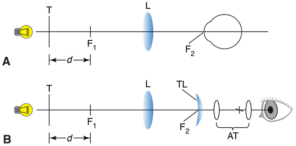
Figure 7-23 A, The optometer principle. T is an illuminated target. When the subject’s eye is placed at the focal point (F2) of the positive lens (L), the vergence at the eye is directly proportional to the distance (d), measured from the first focal point (F1) of lens (L). B, The optometer principle applied to the lensmeter. The test lens (TL) is placed at F2, and the target is viewed with an afocal telescope (AT) by the observer. The target is moved along the axis until the vergence at the test lens is equal and opposite to the vertex power of the test lens. The light will then emerge from the test lens with zero vergence (ie, collimated), and the target will be seen in sharp focus by the observer. The afocal telescope magnifies the target, increases the precision of the measurement, and reduces the effect of the observer’s accommodation or refractive error. (Redrawn from Basic and Clinical Science Course Section 2: Optics, Refraction, and Contact Lenses. San Francisco: American Academy of Ophthalmology; 1986–1987:252. Fig 13.)
To summarize, the target is moved until the light that has passed through the fixed lens and spectacle lens is collimated (in the meridian being studied). The viewer then sees a sharp image of the target in the astronomical telescope, regardless of whether she tends to accommodate or has some uncorrected refractive error.
Automated lensmeters measure the deflection of a light path as it passes through various parts of the lens. Computerized compilation of this information then reveals how those regions of the lens bend the light.
Knapp’s Rule
Suppose we have several eyes with the same anterior segment and, therefore, the same anterior focal plane determined by that cornea, anterior chamber depth, and lens. We suppose the eyes differ only in their axial lengths, and for each eye, we place at the anterior focal plane whatever power lens is needed to correct the refractive error of that eye, depending on how long the eye is. Knapp’s rule, illustrated in Figure 1-41 says the size on the retina of the image of a distant object is the same for all those eyes, when each one’s corrective lens is in place. Clinical application of this rule is limited. Eyes may have unequal myopia because of differences in their anterior segments rather than in their axial lengths. The retinal photoreceptors may be spaced farther apart in a longer eye, and spectacles are usually worn closer to the eye than the anterior focal point, which is approximately 17 mm in front of the cornea (see Chapter 1).
Optical Pachymeter
With the optical pachymeter, the thickness of the cornea or the depth of the anterior chamber is measured by lining up prism-split images in the focused slit lamp’s optical section through the eye (Fig 7-24).
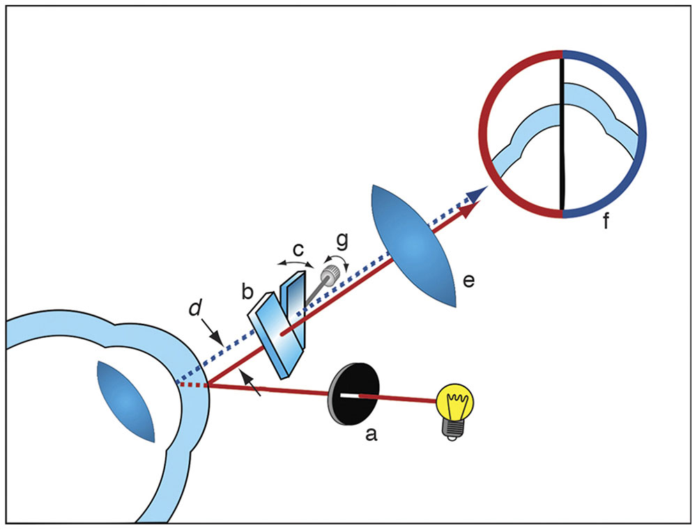
Figure 7-24 In the most common type of optical pachymeter, the cornea is illuminated with a slit beam (a). The image is viewed through a biomicroscope, half through a glass plate orthogonal to the path of light (b) and half through a glass plate rotated through an angle (c). The beam path through the plate is displaced laterally for a distance (d) that varies depending on the angle of rotation. Through the eyepiece (e), a split image is seen (f) wherein half the image comes from the fixed plate and the other half from the rotatable plate. The endothelial surface of one image and the epithelial surface of the other are aligned by the observer by adjustment of the rotatable plate (c), and the corneal thickness measurement is read off a calibrated scale (g). (Courtesy of Neal H. Atebara, MD.)
Applanation Tonometry
The head of the applanation tonometer contains a prism that splits the image of a fluorescing circle of tears to determine when that circle is precisely a certain size (Fig 7-25). Intraocular pressure is inferred from the amount of pressure required to flatten the cornea just enough to create that size circle of tears.
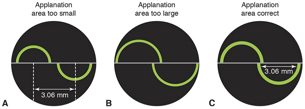
Figure 7-25 The split prism in the applanation head creates 2 offset images. A, When the area of applanation is smaller than 3.06 mm, the arms of the inner semicircles remain some distance apart. B, When the area of applanation is greater than 3.06 mm, the arms of the inner semicircles overlap. C, When the area of applanation is exactly 3.06 mm, the arms of the inner semicircles just touch each other. This is the endpoint for measuring intraocular pressure. The value of 3.06 mm was chosen to approximately balance tear-film surface tension and corneal rigidity. (Courtesy of Neal H. Atebara, MD. Redrawn by C. H. Wooley.)
Specular Microscopy
Specular microscopy is a modality for examining endothelial cells that uses specular reflection from the interface between the endothelial cells and the aqueous humor. The technique can be performed using contact or noncontact methods. In both methods, the instruments are designed to separate the illumination and viewing paths so that reflections from the anterior corneal surface do not obscure the weak reflection arising from the endothelial cell surface.
Endothelial cells can also be visualized through a slit-lamp biomicroscope, if the illumination and viewing axes are symmetrically displaced on either side of the normal line to the cornea (Fig 7-26). A narrow illumination slit must be used; hence, the field of view is narrow. Photographic recording has been made possible by the addition of a long-working-distance microscope system on the viewing axis and flash capability to the illumination system. Patient eye motion is the chief problem with this technique.
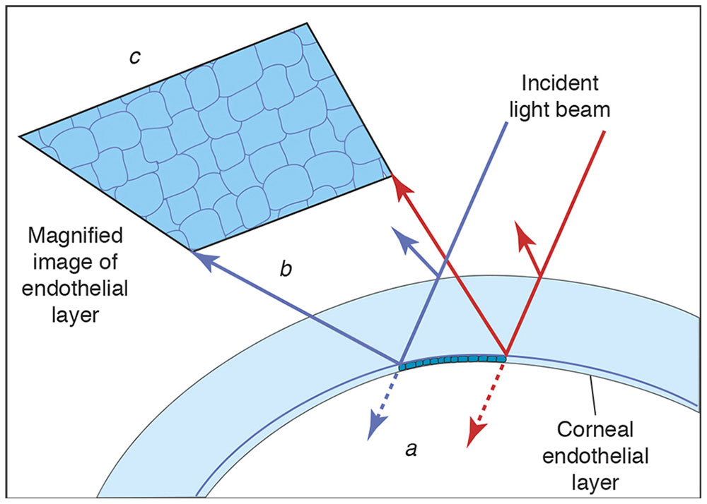
Figure 7-26 Specular reflection microscopy. When a beam of light passes through the transparent corneal structures, most of the light is transmitted (a). However, at each optical interface, such as the corneal endothelium, a proportion of light is reflected (b). This light (called specular reflection) can be collected to form a relatively dim image of the corneal endothelium (c), where individual endothelial cells can be counted. (Courtesy of Neal H. Atebara, MD. Redrawn by C. H. Wooley.)
In contact specular microscopy, the illumination and viewing paths traverse opposite sides of a special microscope objective, the front element of which touches the cornea. This reduces eye rotation and effectively eliminates longitudinal motion that interferes with focus. Contact specular microscopy allows for higher magnifications than slit-lamp biomicroscopy, making cellular detail and endothelial abnormalities more discernible.
Video recording of endothelial layer images makes it possible to document larger, overlapping areas of the endothelial layer. Also, it allows for the recording of high-magnification images, despite patient eye motion.
Wide-field specular microscopy employs techniques to ensure that reflections from the interface between the cornea and contact element do not overlap the image of the endothelial cell layer. Because scattered light from edema in the epithelium and stroma can degrade the endothelial image, variable slit widths are sometimes provided to reduce this problem.
Analysis of specular micrographs may consist simply of assessment of cell appearance together with notation of abnormalities such as guttae or keratic precipitates. Frequently, cell counts are desired; these are often obtained by superimposing a transparent grid of specific dimensions on the endothelial image (photograph or video) and simply counting the cells in a known area. Cell-size distribution can be determined by computer analysis after cell boundaries have been determined digitally. The normal cell density in young people exceeds 3000 cells/mm2; the average density in the older age group susceptible to cataract is 2250 cells/mm2, which suggests a gradual decline with age.
Specular microscopy has been important in studying the morphology of the endothelium and in quantifying damage to the endothelium produced by various surgical procedures and intraocular devices.
Keratometer
The keratometer is used to measure the curvature of the central outer corneal surface by measuring the size of a reflected image in each meridian (or only in the meridians of greatest and least curvature). The measurement is accomplished by lining up prism-doubled images at a distance regulated by sharpness of focus (Fig 7-27). This measurement is performed at only one diameter, 3 mm, in a limited choice of meridians, and is therefore lacking the detail provided by more elaborate topography.


