Figure 3-1 Observation system: light path from patient’s pupil, through mirror, to observer’s retina. (Illustration by C. H. Wooley.)
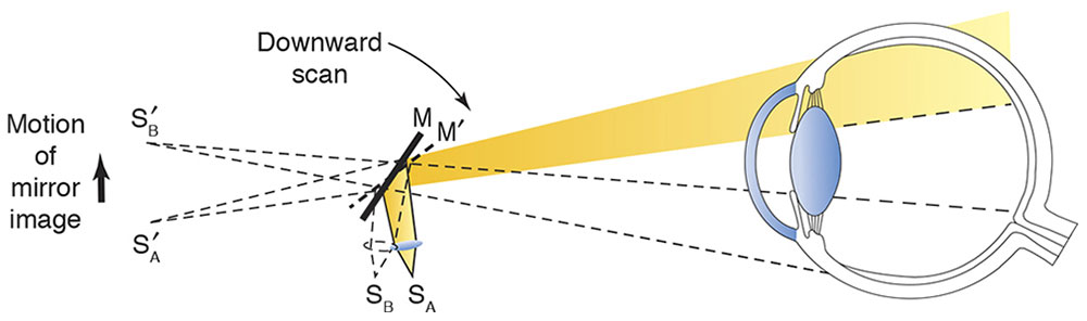
Figure 3-2 Illumination system: position of source (S) with plano mirror (M) effect.
Alternatively, when the distance between the convex lens and the filament is increased by moving the sleeve on the handle, convergent light is emitted. In this situation, the image of the filament appears between the examiner and the patient, as if the light were reflected off a concave mirror (Fig 3-3). Early retinoscopes actually used flat and concave mirrors to achieve these effects.
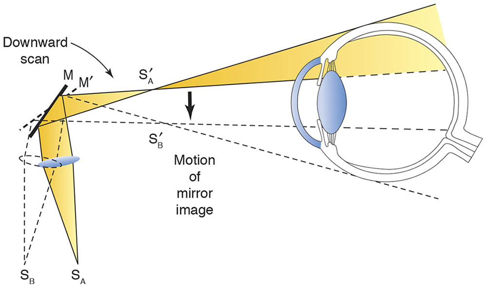
Figure 3-3 Illumination system: position of source with concave mirror effect.
Retinoscopy is usually performed using the plano mirror setting. We restrict our discussion to the plano mirror effect; recall that in the concave mirror effect, the direction of motion is opposite that of the plano mirror effect. Not all retinoscopes employ the same sleeve position for the plano mirror setting. For example, the original Copeland retinoscope is in plano position with the sleeve up; the Welch Allyn instrument is in plano position with the sleeve down. The axis of the streak is rotated by rotating the sleeve.
Positioning and Alignment
Ordinarily, the examiner uses his or her right eye to perform retinoscopy on the patient’s right eye, and the left eye for the patient’s left eye. Doing so prevents the examiner’s head from moving into the patient’s line of sight and thus inadvertently stimulating accommodation. If the examiner looks directly through the optical centers of the trial lenses while performing retinoscopy, reflections from the lenses may interfere. In general, if the examiner is too far off-axis, unwanted spherical and cylindrical errors may occur. The optimal alignment is just off center, where the lens reflections can still be seen between the center of the pupil and the lateral edge of the lens.
Fixation and Fogging
Retinoscopy should be performed with the patient’s accommodation relaxed. The patient should fixate at a distance on a nonaccommodative target. For example, the target may be a dim light at the end of the room or a large Snellen letter (20/200 or 20/400 size). Children typically require pharmacologic cycloplegia.
The Retinal Reflex
The projected streak illuminates an area of the patient’s retina, and this light returns to the examiner. By observing characteristics of this reflex, the examiner determines the refractive status of the eye. If the patient’s eye is emmetropic, the light rays emerging from the patient’s pupil are parallel to one another; if the eye is myopic, the rays are convergent (Fig 3-4); and if the eye is hyperopic, the rays are divergent. Through the peephole in the retinoscope, the emerging rays are seen as a red reflex in the patient’s pupil. If the examiner (specifically, the peephole of the retinoscope) is at the patient’s far point, all the light leaving the patient’s pupil enters the peephole and illumination is uniform. However, if the far point of the patient’s eye is not at the peephole of the retinoscope, only some of the rays emanating from the patient’s pupil enter the peephole, and illumination of the pupil appears incomplete.
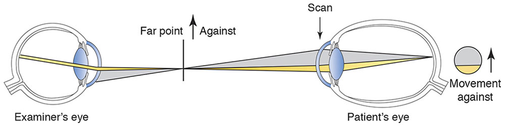
Figure 3-4 Observation system for myopia.
If the far point is between the examiner and the patient, the emerging rays will have focused and then diverged. The border between the dark and lighted portions of the pupil will move in a direction opposite to the motion (sweep) of the retinoscope streak (known as against movement) as it is moved across the patient’s pupil. If the far point is behind the examiner, the light moves in the same direction as the sweep (known as with movement; Fig 3-5).
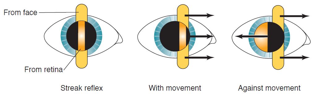
Figure 3-5 Retinal reflex movement. Note movement of the streak from face and from retina in with versus against movement. (Illustration by C. H. Wooley.)
The condition in which the light fills the pupil and does not move is known as neutrality (Fig 3-6). The far point is moved with placement of a correcting lens in front of the patient’s eye. At neutrality, if the examiner moves forward (in front of the far point), with movement is seen; if the examiner moves back and away from the far point, against movement is seen.
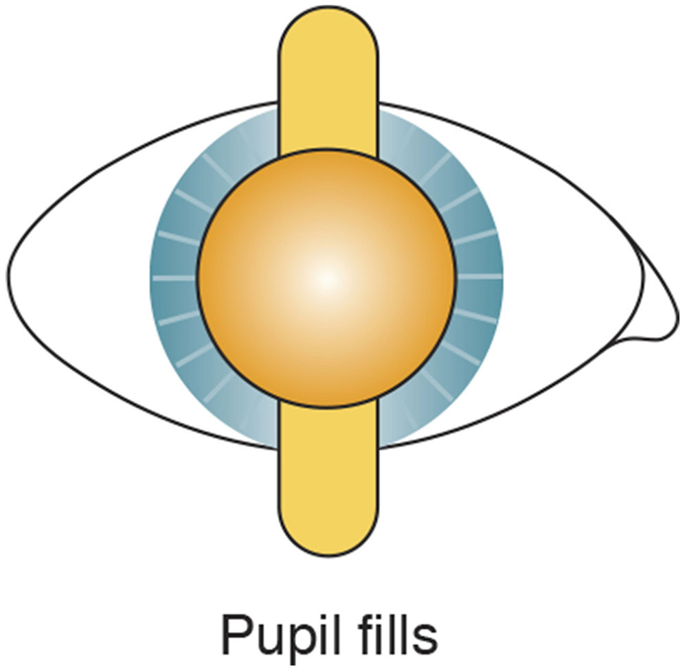
Figure 3-6 Neutrality reflex. Far point of the eye is conjugate with the peephole of the retinoscope. (Illustration by C. H. Wooley.)
Characteristics of the reflex
The moving retinoscopic reflex has 3 main characteristics (Fig 3-7):
- Speed. The reflex seen in the pupil moves slowest when the far point is distant from the examiner (peephole of the retinoscope). As the far point is moved toward the peephole, the speed of the reflex increases. In other words, large refractive errors have a slow-moving reflex, whereas small errors have a fast reflex.
- Brilliance. The reflex is dull when the far point is distant from the examiner; it becomes brighter as neutrality is approached. Against reflexes are usually dimmer than with reflexes.
- Width. When the far point is distant from the examiner, the streak is narrow. As the far point is moved closer to the examiner, the streak broadens and, at neutrality, fills the entire pupil. This situation applies only to with movement reflexes.
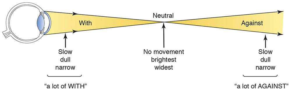
Figure 3-7 Characteristics of the moving retinal reflex on both sides of neutrality. The vertical arrows indicate the position of the retinoscope with regard to the point of neutrality. (Illustration by C. H. Wooley.)
The Correcting Lens
When the examiner uses the appropriate correcting lenses (with either loose lenses or a phoropter), the retinoscopic reflex is neutralized. In other words, when the examiner brings the patient’s far point to the peephole, the reflex fills the patient’s entire pupil (Fig 3-8). The power of the correcting lens (or lenses) neutralizing the reflex helps determine the patient’s refractive error.
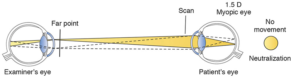
Figure 3-8 Observation system at neutralization.
The examiner determines the refractive error at the distance from which he or she is working. The dioptric equivalent of the working distance (ie, the inverse of the distance) must be subtracted from the power of the correcting lens to determine the actual refractive error of the patient’s eye. Because a common working distance is 67 cm, many phoropters have a 1.50 D (1.00/0.67 m) “working-distance lens” for use during retinoscopy (however, this lens can produce bothersome reflexes).
Any working distance may be used. If the examiner prefers to move closer to the patient for a brighter reflex, the working-distance correction is adjusted accordingly. For example, suppose that an examiner obtains neutralization with a total of +4.00 D over the eye (gross retinoscopy) at a working distance of 67 cm. Subtracting 1.50 D for the working distance yields a refractive correction of +2.50 D.
Finding Neutrality
In against movement, the far point is between the examiner and the patient. Therefore, to bring the far point to the peephole of the retinoscope, a minus lens is placed in front of the patient’s eye. Similarly, in the case of with movement, a plus lens is placed in front of the patient’s eye. This procedure gives rise to the simple clinical rule: If with movement is observed, add plus power (or subtract minus power); if against movement is observed, add minus power (or subtract plus power) (Fig 3-9).
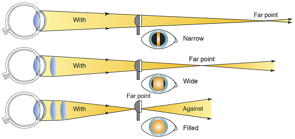
Figure 3-9 Approaching neutrality. Change in width of the reflex as neutrality is approached. Note that working distance remains constant, and the far point is pulled in with plus lenses. (Illustration by C. H. Wooley.)
Because it is easier to work with the brighter, sharper with movement image, one should “overminus” the eye and obtain a with reflex; then reduce the minus power (or add plus power) until neutrality is reached. Be aware that the slow, dull reflexes of high-refractive errors may be confused with the neutrality reflex. Media opacities may also produce dull reflexes.
Retinoscopy of Regular Astigmatism
Most eyes have some regular astigmatism. In such cases, light is refracted differently by the 2 principal astigmatic meridians. Let us consider how the retinoscope works in greater detail and apply it to astigmatism.
Sweeping the retinoscope back and forth measures the power along only a single axis. Moving the retinoscope from side to side (with the streak oriented at 90°) measures the optical power in the 180° meridian. Power in this meridian is provided by a cylinder at the 90° axis. The convenient result is that the streak of the retinoscope is aligned with the axis of the correcting cylinder being tested. In a patient with regular astigmatism, one seeks to neutralize 2 reflexes, 1 from each of the principal meridians.
Finding the cylinder axis
Before the powers in each of the principal meridians can be determined, the axes of the meridians must be determined. Four characteristics of the streak reflex aid in this determination:
- Break. A break is observed when the streak is not oriented parallel to 1 of the principal meridians. The reflex streak in the pupil is not aligned with the streak projected on the iris and surface of the eye, and the line appears broken (Fig 3-10). The break disappears (ie, the line appears continuous) when the projected streak is rotated to the correct axis.
- Width. The width of the reflex in the pupil varies as it is rotated around the correct axis. The reflex appears narrowest when the streak, or intercept, aligns with the axis (Fig 3-11).
- Intensity. The intensity of the line is brighter when the streak is on the correct axis.
- Skew. Skew (oblique motion of the streak reflex) may be used to refine the axis in small cylinders. If the retinoscope streak is off-axis, it moves in a slightly different direction from that of the pupillary reflex (Fig 3-12). The reflex and streak move in the same direction when the streak is aligned with 1 of the principal meridians.
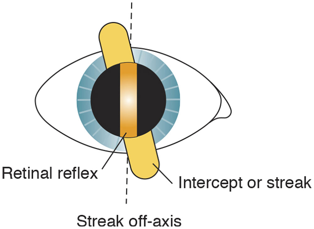
Figure 3-10 Break. The retinal reflex is discontinuous with the intercept when the streak is off the correct axis (dashed lines). (Illustration by C. H. Wooley.)
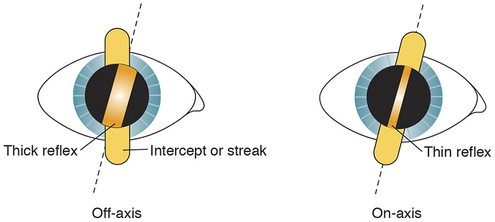
Figure 3-11 Width, or thickness, of the retinal reflex. The examiner locates the axis where the reflex is thinnest (dashed lines). (Illustration by C. H. Wooley.)
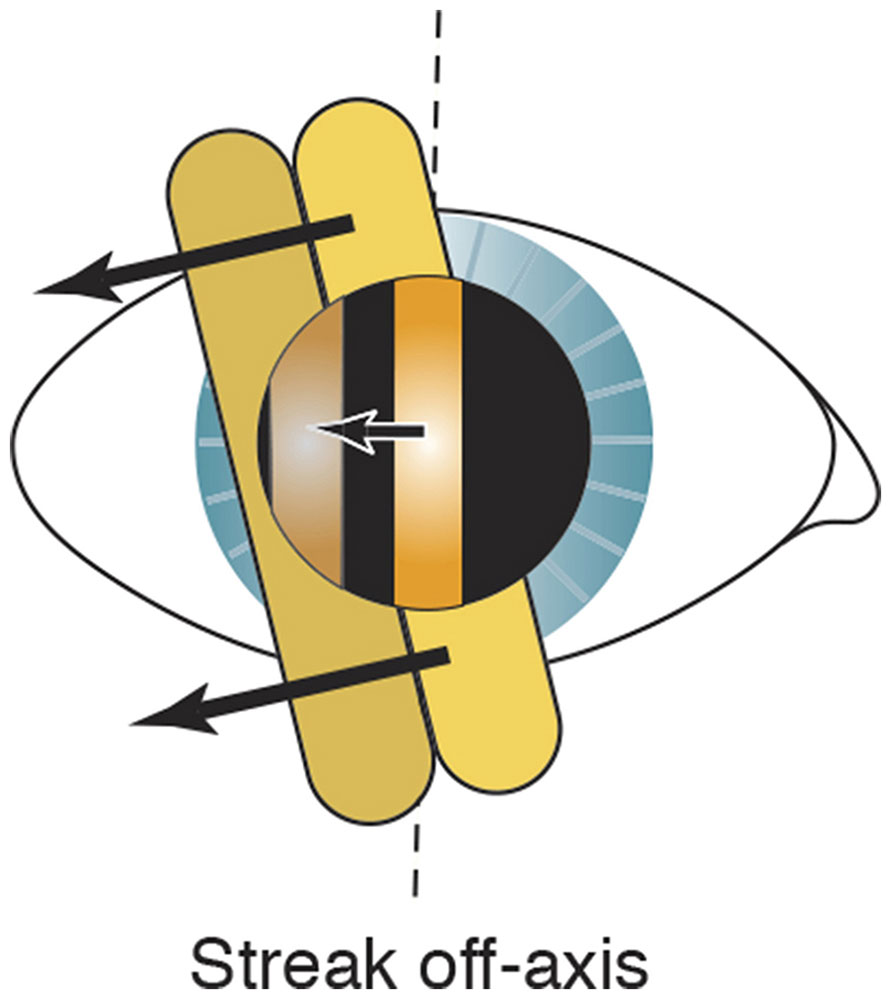
Figure 3-12 Skew. The arrows indicate that movements of the reflex (single arrow) and intercept (2 arrows) are not parallel. The reflex and intercept do not move in the same direction but are skewed when the streak is off-axis. Dashed lines indicate the on-axis line. (Illustration by C. H. Wooley.)
When the streak is aligned at the correct axis, the sleeve may be lowered (Copeland instrument) or raised (Welch Allyn instrument) to narrow the streak, allowing the axis to be determined more easily (Fig 3-13).
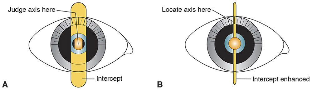
Figure 3-13 Locating axis on the protractor. A, First, determine the astigmatic axis. B, Second, adjust the sleeve to enhance the intercept until the filament is observed as a fine line pinpointing the axis. (Illustration by C. H. Wooley.)
This axis can be confirmed through a technique known as straddling, which is performed with the estimated correcting cylinder in place (Fig 3-14). The retinoscope streak is turned 45° off-axis in both directions, and if the axis is correct, the width of the reflex should be equal in both off-axis positions. If the axis is not correct, the widths are unequal in these 2 positions. The axis of the correcting plus-cylinder should be moved toward the narrower reflex and the straddling repeated until the widths are equal. This technique is often more accurate than subjective cross-cylinder axis refinement.
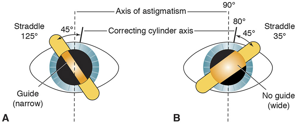
Figure 3-14 Straddling. The straddling meridians are 45° off the correcting cylinder axis, at roughly 35° and 125°. As the examiner moves back from the eye while comparing the meridians, the reflex at 125° remains narrow (A) at the same distance that the reflex at 35° has become wide (B). This dissimilarity indicates an axis error; the narrow reflex (A) is the guide toward which the examiner must turn the correcting cylinder axis. (Illustration by C. H. Wooley.)
Finding the cylinder power
After the 2 principal meridians are identified, the previously explained spherical techniques are applied to each axis:
- With 2 spheres. Neutralize 1 axis with a spherical lens; then neutralize the axis 90° away. The difference between these readings is the cylinder power. For example, if the 90° axis is neutralized with a +1.50 sphere and the 180° axis is neutralized with a +2.25 sphere, the gross retinoscopy is +1.50 +0.75 × 180. The examiner’s working distance (ie, +1.50) is subtracted from the sphere to obtain the final refractive correction: plano +0.75 × 180.
- With a sphere and cylinder. Neutralize 1 axis with a spherical lens. To enable the use of with reflexes, neutralize the less plus axis first. Then, with this spherical lens in place, neutralize the axis 90° away by adding a plus cylindrical lens. The spherocylindrical gross retinoscopy is read directly from the trial lens apparatus.
It is also possible to use 2 cylinders at right angles to each other for this gross retinoscopy.
Aberrations of the Retinoscopic Reflex
With irregular astigmatism, almost any type of aberration may appear in the reflex. Spherical aberrations tend to increase the brightness at the center or periphery of the pupil, depending on whether they are positive or negative.
As neutrality is approached, 1 part of the reflex may be myopic, whereas the other may be hyperopic relative to the position of the retinoscope. This situation produces a scissors reflex. Causes of the scissors reflex include keratoconus, irregular corneal astigmatism, corneal or lenticular opacities, and spherical aberration.
All of these aberrant reflexes, in particular spherical aberration, are more noticeable in patients with large scotopic pupils. When a large pupil is observed during retinoscopy, the examiner should focus on neutralizing the central portion of the light reflex.
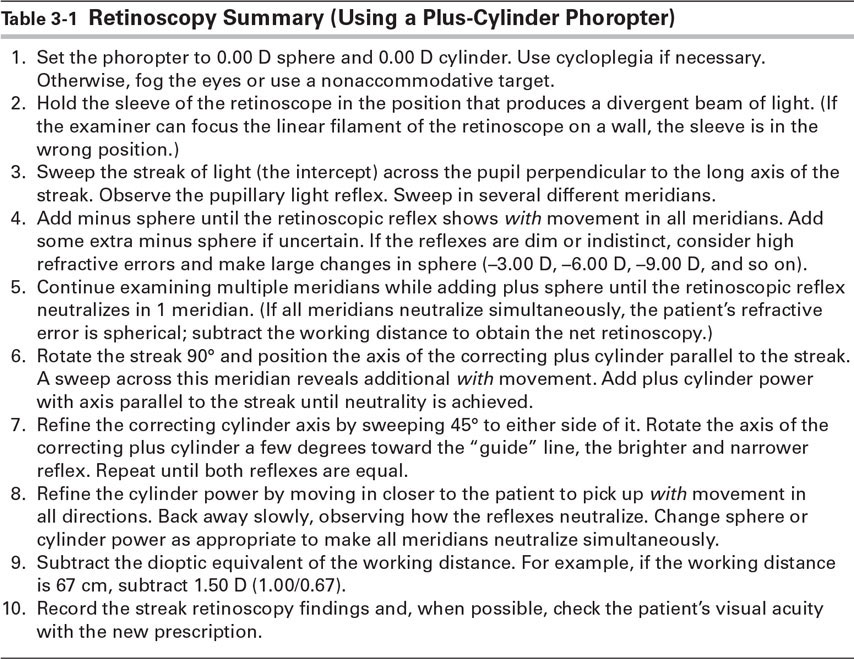
Table 3-1 provides a summary of the technique of retinoscopy using a plus-cylinder phoropter.
Table 3-1
Corboy JM. The Retinoscopy Book: An Introductory Manual for Eye Care Professionals. 4th ed. Thorofare, NJ: Slack; 1995.
Wirtschafter JD, Schwartz GS. Retinoscopy. In: Tasman W, Jaeger EA, eds. Duane’s Clinical Ophthalmology [CD-ROM]. Vol 1. Philadelphia: Lippincott Williams & Wilkins; 2006:chap 37.
Subjective Refraction Techniques
In subjective refraction techniques, the examiner relies on the patient’s responses to determine the refractive correction. If all refractive errors were spherical, subjective refraction would be easy. However, determining the astigmatic portion of the correction is more complex, and various subjective refraction techniques may be used. The Jackson cross cylinder is the most common instrument used in determining the astigmatic correction. However, we begin by discussing the astigmatic dial technique because it is easier to understand.
Astigmatic Dial Technique
An astigmatic dial is a test chart with radially arranged lines that may be used to determine the axes of astigmatism. A pencil of light from a point source is imaged by an astigmatic eye as a conoid of Sturm. The spokes of the astigmatic dial that are parallel to the principal meridians of the eye’s astigmatism are imaged as sharp lines, which correspond to the focal lines of the conoid of Sturm.
Figure 3-15A shows an eye with compound hyperopic astigmatism and how it sees an astigmatic dial. The vertical line of the astigmatic dial is the blackest and sharpest because the vertical focal line of each conoid of Sturm is closer to the retina than the horizontal focal line is. By accommodating, however, the patient might pull both focal lines forward, far enough to make even the horizontal line of the astigmatic dial clear. To avoid accommodation, fogging is used. Sufficient plus sphere is placed before the eye to pull both focal lines into the vitreous, creating compound myopic astigmatism (Fig 3-15B).
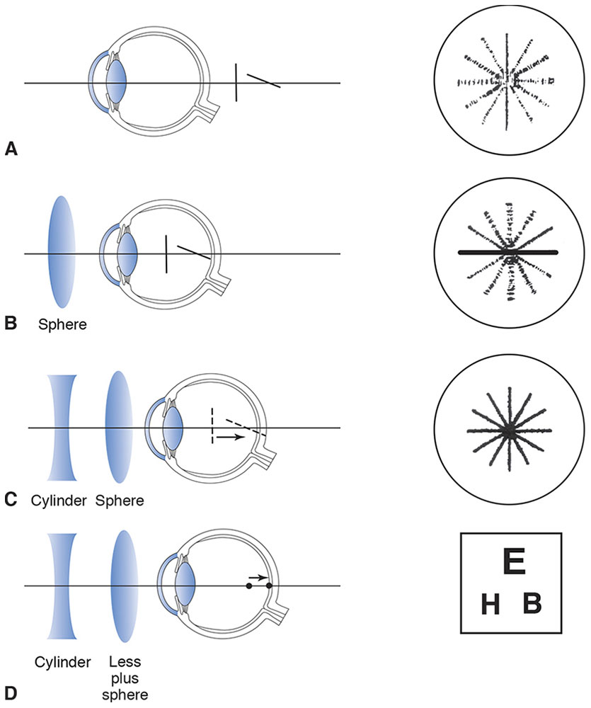
Figure 3-15 Astigmatic dial technique. A, Conoid of Sturm and retinal image of an astigmatic dial as viewed by an eye with compound hyperopic astigmatism. B, Fogging to produce compound myopic astigmatism. C, The conoid of Sturm is collapsed to a single point. D, Minus sphere is added (or plus sphere subtracted) to produce a sharp image, and a visual acuity chart is used for viewing.
Because accommodating with the eye fogged causes increased blurring of the lines, the patient relaxes accommodation. The focal line closest to the retina can then be identified with certainty as the horizontal line because it is now the blackest and sharpest line of the astigmatic dial. Note that the terms blackest and sharpest are more easily understood by patients and should be used in place of the word clearest.
After the examiner locates 1 of the principal meridians of the astigmatism, the conoid of Sturm can be collapsed by moving the anterior focal line back toward the posterior focal line. This task can be accomplished by adding a minus cylinder with an axis parallel to the anterior focal line. In Figure 3-15C the vertical focal line has been moved back to the position of the horizontal focal line and collapsed to a point by the addition of a minus cylinder with an axis at 90°. Notice that the minus cylinder is placed with its axis perpendicular to the blackest meridian on the astigmatic dial. Also note that as the conoid of Sturm is collapsed, the focal lines disappear into a point focus.
All of the lines of the astigmatic dial now appear equally black but still are not in perfect focus, because the eye remains slightly fogged to control accommodation. At this point, a visual acuity chart is used; plus sphere is removed until the best visual acuity is obtained (Fig 3-15D).
In summary, the following steps are used in astigmatic dial refraction:
- Obtain the best visual acuity using spheres only.
- Fog the eye to approximately 20/50 by adding plus sphere.
- Ask the patient to identify the blackest and sharpest line of the astigmatic dial.
- Add minus cylinder with the axis perpendicular to the blackest and sharpest line until all lines appear equal. (If using a positive cylinder phoropter, add plus cylinder with the axis parallel to the blackest and sharpest line until all lines appear equal.)
- Reduce plus sphere (or add minus) until the best visual acuity is obtained with the visual acuity chart.
Astigmatic dial refraction can also be performed with plus cylinder equipment, but this technique must be used in a way that simulates minus cylinder effect. All of the above steps remain the same except for step 4, which becomes “Add plus cylinder with the axis parallel to the blackest and sharpest line.” As each 0.25 D of plus cylinder power is added, change the sphere simultaneously by 0.25 D in the minus direction. Doing so simulates minus cylinder effect exactly by moving the anterior focal line posteriorly without changing the position of the posterior focal line.
Michaels DD. Visual Optics and Refraction: A Clinical Approach. 3rd ed. St Louis: Mosby; 1985:319–322.
Stenopeic Slit Technique
The stenopeic slit is an opaque trial lens with an oblong slit whose width forms a pinhole with respect to vergence perpendicular to the slit (Fig 3-16). If an examiner is unable to decipher the astigmatism by performing the usual retinoscopy because of the subject eye’s irregular astigmatism or unclear media, he or she may neutralize the refractive error with spherical lenses and the slit at various meridians to find a spherocylindrical correction. This correction can then be refined subjectively. This process is especially useful for patients with small pupils and lenticular or corneal opacities. If the subject can accommodate, fog and unfog using plus sphere to find the most plus power accepted. Then turn the slit until the subject says the image is sharpest. If, for example, –3.00 D sphere is best there, when the slit is oriented vertically, this finding indicates –3.00 D at 90° in a power cross. If the best sphere with the slit oriented horizontally is –5.00 D, then the result is –3.00 –2.00 × 90.
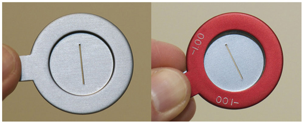
Figure 3-16 Stenopeic slit. The image on the right demonstrates the placement of a spherical lens in front of the stenopeic slit in order to determine the best visual acuity. (Courtesy of Tommy Korn, MD.)
Cross-Cylinder Technique
The Jackson cross cylinder, in Edward Jackson’s words, is probably “far more useful, and far more used” than any other lens in clinical refraction. Every ophthalmologist should be familiar with the principles involved in its use. Although the cross cylinder is usually used to refine the cylinder axis and power of a refraction that has already been obtained, it can also be used for the entire astigmatic refraction.
The first step in cross-cylinder refraction is adjusting the sphere to yield the best visual acuity with accommodation relaxed. Begin by placing the prescription the patient is wearing into a trial frame or phoropter. Fog the eye to be examined with plus sphere while the patient views a visual acuity chart; then decrease the fog until the best visual acuity is obtained. If astigmatism is present, decreasing the fog places the circle of least confusion on the retina, creating a mixed astigmatism. Then use test figures that are 1–2 lines larger than the patient’s best visual acuity. At this point, introduce the cross cylinder, first for refinement of cylinder axis and then for refinement of cylinder power.
If no cylindrical correction is present initially, the cross cylinder may still be used, placed at 90° and 180°, to check for the presence of astigmatism. If a preferred flip position is found, cylinder is added with the axis parallel to the respective plus or minus axis of the cross cylinder until the 2 flip choices are equal. If no preference is found with the cross-cylinder axes at 90° and 180°, then check the axes at 45° and 135° before assuming that no astigmatism is present. Once any cylinder power is found, axis and power should be refined in the usual manner.
Another method of determining the presence of astigmatism is to dial 0.50 D of cylinder into the phoropter (while preserving the spherical equivalent with a compensatory 0.25 D change in the sphere). Ask the patient to slowly rotate the cylinder axis once around using the knob on the phoropter. If doing so has no effect, there is no clinically significant astigmatism. If the patient finds a preferred position, it becomes the starting point for the cross-cylinder refinement.
Always refine cylinder axis before refining cylinder power. This sequence is necessary because the correct axis may be found in the presence of an incorrect power, but the full cylinder power is found only in the presence of the correct axis.
Refinement of cylinder axis involves the combination of cylinders at oblique axes. When the axis of the correcting cylinder is not aligned with that of the astigmatic eye’s cylinder, the combined cylinders produce residual astigmatism with a meridian roughly 45° away from the principal meridians of the 2 cylinders. To refine the axis, position the principal meridians of the cross cylinder 45° away from those of the correcting cylinder (if using a handheld Jackson cross cylinder, the stem of the lens handle will be parallel to the axis of the correcting cylinder). Present the patient with alternative flip choices, and select the choice that is the blackest and sharpest to the patient. Then rotate the axis of the correcting cylinder toward the corresponding plus or minus axis of the cross cylinder (plus cylinder axis is rotated toward the plus cylinder axis of the cross cylinder, and minus cylinder axis is rotated toward the minus cylinder axis of the cross cylinder). Low-power cylinders are rotated in increments of 15°; high-power cylinders are rotated by smaller amounts, usually 5°. Repeat this procedure until the flip choices appear equal.
To refine cylinder power, align the cross-cylinder axes with the principal meridians of the correcting lens (Fig 3-17). The examiner should change cylinder power according to the patient’s responses; the spherical equivalent of the refractive correction should remain constant to keep the circle of least confusion on the retina. Ensure that the correction remains constant by changing the sphere half as much and in the opposite direction as the cylinder power is changed. In other words, for every 0.50 D of cylinder power change, change the sphere by 0.25 D in the opposite direction. Periodically, the sphere power should be adjusted for the best visual acuity.
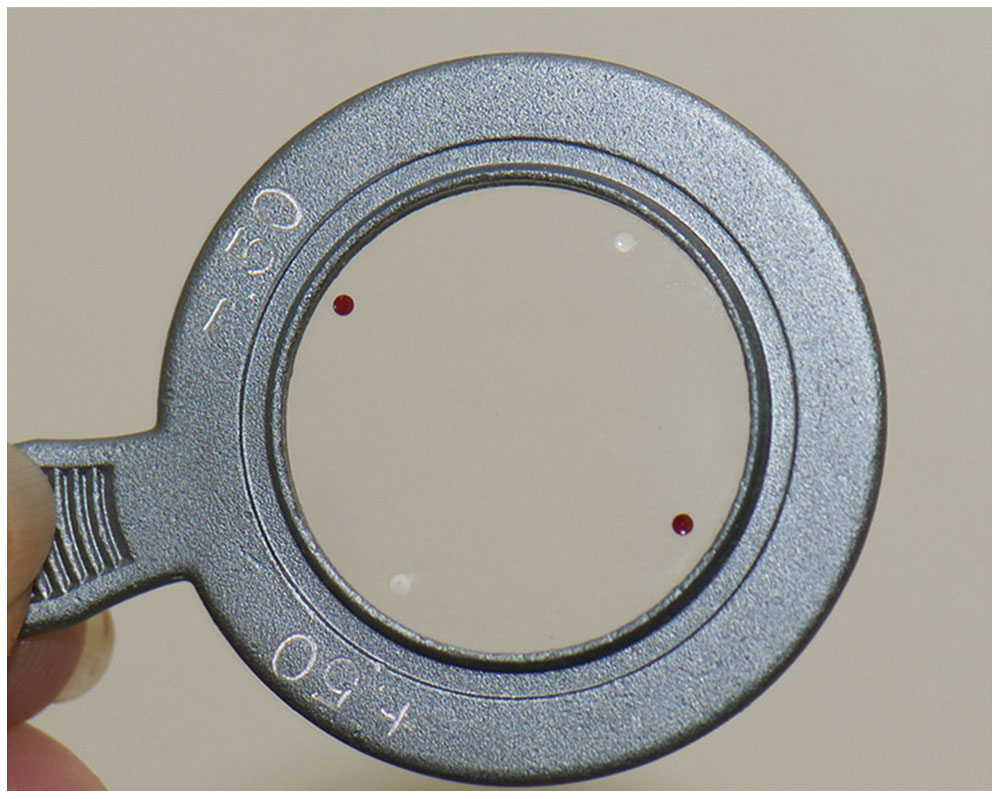
Figure 3-17 Jackson cross cylinder. (Courtesy of Tommy Korn, MD.)
Continue to refine cylinder power until the patient reports that both flip choices appear equal. At that point, the 2 flip choices produce equal and opposite mixed astigmatism, blurring the visual acuity chart equally.
Remember to use the proper-power cross cylinder for the patient’s visual acuity level. For example, a ±0.25 D cross cylinder is commonly used with visual acuity levels of 20/30 and better. A high-power cross cylinder (±0.50 D or ±1.00 D) allows a patient with poorer vision to recognize differences in the flip choices.
The patient may be confused with prior choices during cross-cylinder refinement. Giving different numbers to subsequent choices avoids this problem: “Which is better, 1 or 2, 3 or 4?” and so forth. If the patient persists in choosing either the first or second number, reverse the order of presentation to check for consistency.
Table 3-2 summarizes the cross-cylinder refraction technique.
Table 3-2
Guyton DL. Retinoscopy: Minus Cylinder Technique, 1986; Retinoscopy: Plus Cylinder Technique, 1986; Subjective Refraction: Cross-Cylinder Technique, 1987. Reviewed for currency, 2007. Clinical Skills DVD Series [DVD]. San Francisco: American Academy of Ophthalmology.
Wunsh SE. The cross cylinder. In: Tasman W, Jaeger EA, eds. Duane’s Clinical Ophthalmology [CD-ROM]. Vol 1. Philadelphia: Lippincott Williams & Wilkins; 2006:chap 38.
Refining the Sphere
After cylinder power and axis have been determined using either the astigmatic dial technique or the cross-cylinder method, the final step of determining monocular refraction is to refine the sphere. The endpoint in the refraction is the strongest plus sphere, or weakest minus sphere, that yields the best visual acuity. The following discussion briefly considers some of the methods used.
When the cross-cylinder technique has been used to determine the cylinder power and axis, the refractive error is presumed to a single point. Add plus sphere in +0.25 D increments until the patient reports decreased vision. If no additional plus sphere is accepted, add minus sphere in –0.25 D increments until the patient achieves the most optimal visual acuity.
Using accommodation, the patient can compensate for excess minus sphere. Therefore, it is important to use the least minus sphere necessary to reach the best visual acuity. In effect, accommodation creates a reverse Galilean telescope, whereby the eye generates more plus power as minus power is added to the trial lenses before the eye. As this minus power increases, the patient observes that the letters appear smaller and more distant.
The patient should be told what to look for. Before subtracting each 0.25 D increment, tell the patient that the letters may appear sharper and brighter or smaller and darker, and ask the patient to report any such change. Reduce the amount of plus sphere only if the patient can actually read more letters.
If the astigmatic dial technique has been used and the astigmatism is neutralized (ie, if all the lines on the astigmatic dial are equally sharp or equally blurred), the eye should still be fogged; additional plus sphere only increases the blur. Therefore, use minus sphere to reduce the sphere power until the best visual acuity is achieved. Again, the examiner should be careful not to add too much minus sphere.
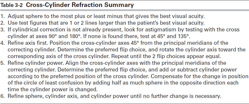
To verify the spherical endpoint, the duochrome test (also known as the red-green or bichrome test) is used (Fig 3-18). A split red-green filter makes the background of the visual acuity chart appear vertically divided into a red half and a green half. Because of the chromatic aberration of the eye, the shorter (green) wavelengths are focused in front of the longer (red) wavelengths. The eye typically focuses near the midpoint of the spectrum, between the red and green wavelengths. With optimal spherical correction, the letters on the red and green halves of the chart appear equally sharp. The commercial filters used in the duochrome test produce a chromatic interval of approximately 0.50 D between the red and green wavelengths. When the image is clearly focused in white light, the eye is 0.25 D myopic for the green letters and 0.25 D hyperopic for the red letters.
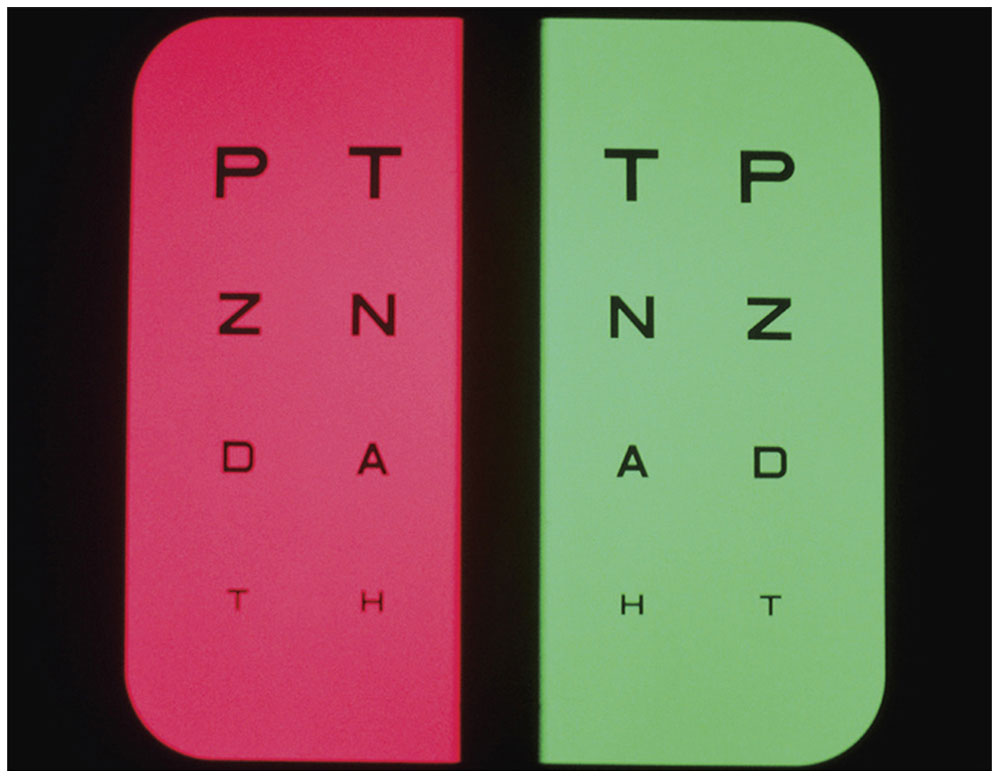
Figure 3-18 Duochrome test. (Courtesy of Tommy Korn, MD.)
Each eye is tested separately for the duochrome test, which is begun with the eye slightly fogged (by 0.50 D) to relax accommodation. The letters on the red side should appear sharper; the clinician should add minus sphere until the 2 sides appear the same. If the patient responds that the letters on the green side are sharper, the patient is overminused, and more plus power should be added. Some clinicians use the RAM-GAP mnemonic—“red add minus; green add plus”—to recall how to use the duochrome test.
Because this test is based on chromatic aberration and not on color discrimination, it is used even with color-blind patients (although it may be necessary to identify the sides of the chart as left and right rather than red and green). An eye with overactive accommodation may still require too much minus sphere in order to balance the red and green. Cycloplegia may be necessary. The duochrome test is not used with patients whose visual acuity is worse than 20/30 (6/9), because the 0.50 D difference between the 2 sides is too small to distinguish.
Binocular Balance
The final step of subjective refraction is to make certain that accommodation has been relaxed equally in both eyes. Several methods of binocular balance are commonly used. Most require that the corrected visual acuity be nearly equal in both eyes.
Fogging
When the endpoint refraction is fogged using a +2.00 D sphere before each eye, the visual acuity should be reduced to 20/200–20/100 (6/60–6/30). Place a –0.25 D sphere before first 1 eye and then the other, and rapidly alternate cover; the patient should then be able to identify the eye with the –0.25 D sphere before it as having the sharper image at the 20/100 (6/30) or 20/70 (6/20) level. If the eyes are not in balance, sphere should be added or subtracted in 0.25 increments until balance is achieved.
In addition to testing for binocular balance, the fogging method also provides information about appropriate sphere power. If either eye is overminused or underplussed, the patient should read farther down the chart—as far as 20/70 (6/20), 20/50 (6/15), or even 20/40 (6/12)—with the +2.00 D fogging spheres in place. In this case, the refraction endpoints should be reconsidered.
Prism dissociation
The most sensitive test of binocular balance is prism dissociation. For this test, the refractive endpoints are fogged with +1.00 D spheres, and vertical prisms of 4 or 5 prism diopters (Δ) are placed before 1 eye (Fig 3-19). Use of the prisms causes the patient to see 2 charts, 1 above the other. A single line, usually 20/40 (6/12), is isolated on the chart; the patient sees 2 separate lines simultaneously, 1 for each eye. The patient can readily identify differences between the fogged images in the 2 eyes of as little as 0.25 D sphere. In practice, +0.25 D sphere is placed before 1 eye and then before the other. In each instance, if the eyes are balanced, the patient reports that the image corresponding to the eye with the additional +0.25 D sphere is blurrier. After a balance is established between the 2 eyes, remove the prism and reduce the fog binocularly until the best visual acuity is obtained.
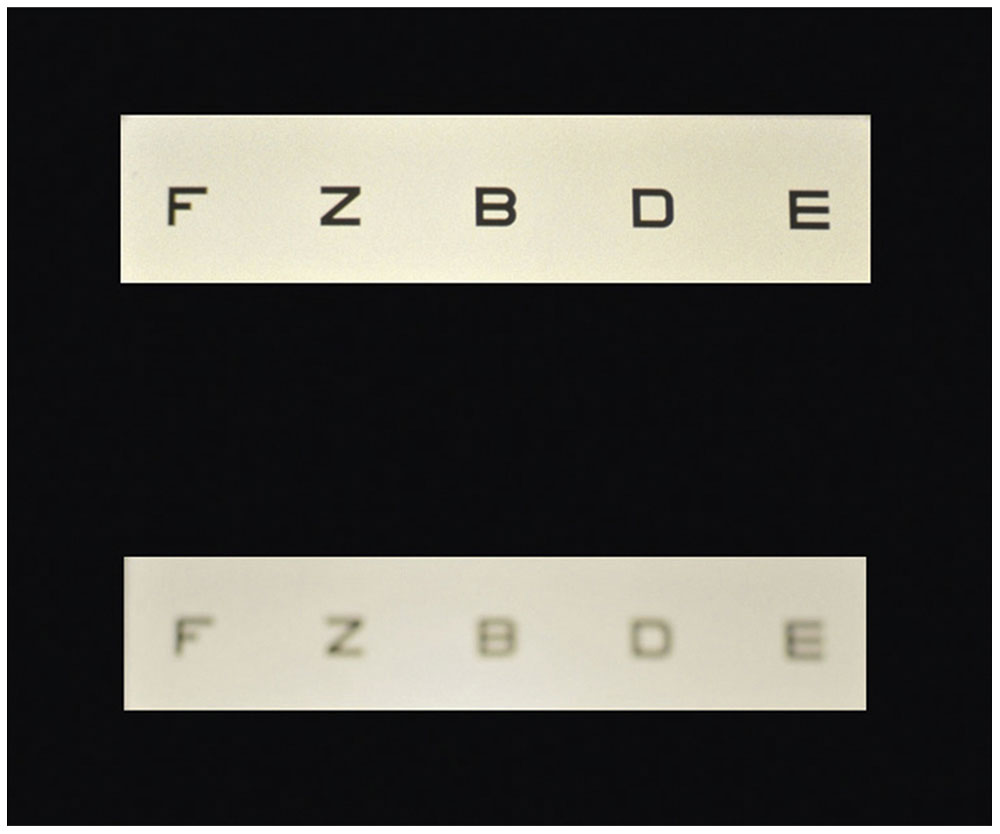
Figure 3-19 Binocular balancing by prism dissociation from patient perspective. (Courtesy of Tommy Korn, MD.)
Cycloplegic and Noncycloplegic Refraction
Ideally, refractive error is measured with accommodation relaxed. The amount of habitual accommodative tone varies from person to person, and even within an individual it varies at times and with age. Because determining this variable may not always be possible, cycloplegic drugs are sometimes used. The indication and appropriate dosage for a specific cycloplegic drug depend on the patient’s age, accommodative amplitude, and refractive error.
A practical approach to obtaining satisfactory refraction is to perform a careful noncycloplegic (or manifest) refraction, ensuring relaxed accommodation with fogging or other nonpharmacologic techniques. If the results are inconsistent or variable, a cycloplegic refraction should be performed. If the findings of these 2 refractions are similar, the prescription may be based on the manifest refraction. If there is a disparity, a postcycloplegic evaluation may be necessary. Most children require cycloplegic refraction because of their high amplitude of accommodation. For more details on the cycloplegic drugs used in adults and children, please refer to the pharmacotherapeutics chapter in BCSC Section 2, Fundamentals and Principles of Ophthalmology.
Overrefraction
Phoropters may be used to refract the eyes of patients with highly ametropic vision. Variability in the vertex distance of the refraction (the distance from the back surface of the spectacle lens to the cornea) and other induced errors make prescribing directly from the phoropter findings unreliable.
Some of these problems can be avoided if highly ametropic eyes are refracted over the patients’ current glasses (overrefraction). If the new lenses are prescribed with the same base curve as the current lenses and are fitted in the same frames, many potential difficulties can be circumvented, including vertex distance error and pantoscopic tilt error, as well as problems caused by marginal astigmatism and chromatic aberration. Overrefraction may be performed with loose lenses (using trial lens clips such as Halberg trial clips), with a standard phoropter in front of the patient’s glasses, or with some automated refracting instruments.
If the patient is wearing spherical lenses, the new prescription is easy to calculate by combining the current spherical correction with the spherocylindrical overrefraction. If the current lenses are spherocylindrical and the cylinder axis of the overrefraction is not at 0° or 90° to the present correction, other methods previously discussed are used to determine the resultant refraction. Such lens combinations were often determined with a lensmeter used to read the resultant lens power through the combinations of the old glasses and the overrefraction correction. This procedure is awkward and prone to error because the lenses may rotate with respect to one another on transfer to the lensmeter. Manual calculation is possible but complicated. Programmable calculators can be used to perform the trigonometric combination of cylinders at oblique axes, but they may not be readily available in the clinic.
Overrefraction has other uses. For example, a patient wearing a soft toric contact lens may undergo overrefraction for the purpose of ordering new lenses. An overrefraction is especially useful for patients wearing rigid, gas-permeable, hard contact lenses for irregular corneal astigmatism or corneal transplants. Overrefraction can also be used in the retinoscopic examination of children.
Spectacle Correction of Ametropias
Ametropia is a refractive error; it is the absence of emmetropia. The most common method of correcting refractive error is through prescription of spectacle lenses.
Spherical Correcting Lenses and the Far Point Concept
The far point plane of the nonaccommodated eye is conjugate with the retina. For a simple lens, distant objects (those at optical infinity) come into sharp focus at the secondary focal point (F2) of the lens. To correct the refractive error of an eye, a correcting lens must place the image it forms (or its F2) at the eye’s far point. The image at the far point plane becomes the object that is focused onto the retina. For example, in a myopic eye, the far point lies somewhere in front of the eye, between it and optical infinity. In this case, the correct diverging lens forms a virtual image of distant objects at its F2, coincident with the far point of the eye (Fig 3-20).
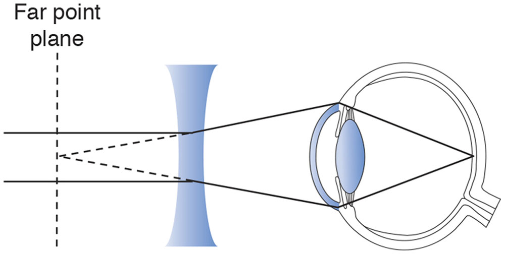
Figure 3-20 A diverging lens is used to correct myopia.
The same principle holds for the correction of hyperopia (Fig 3-21). However, because the far point plane of a hyperopic eye is behind the retina, a converging lens must be chosen in the appropriate power to focus parallel rays of light to the far point plane.
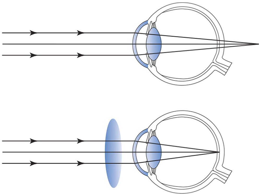
Figure 3-21 A converging lens is used to correct hyperopia.
The Importance of Vertex Distance
For any spherical correcting lens, the distance from the lens to its focal point is constant. Changing the position of the correcting lens relative to the eye also changes the relationship between the F2 of the correcting lens and the far point plane of the eye. With high-power lenses, as used in the spectacle correction of aphakia or high myopia, a small change in the placement of the lens produces considerable blurring of vision unless the lens power is altered to compensate for the new lens position.
With refractive errors greater than ±5.00 D, the vertex distance must be accounted for in prescribing the power of the spectacle lens. A distometer (also called vertexometer) is used to measure the distance from the back surface of the spectacle lens to the cornea with the eyelid closed (Fig 3-22). Moving a correcting lens closer to the eye—whether the lens has plus or minus power—reduces its effective focusing power (the image moves posteriorly away from the fovea), whereas moving it farther from the eye increases its focusing power (the image moves anteriorly away from the fovea).
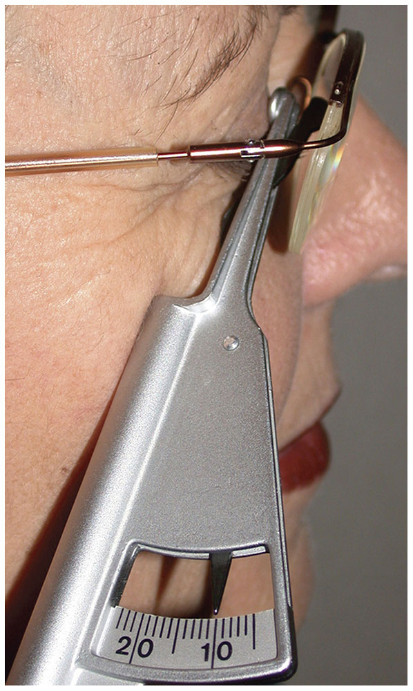
Figure 3-22 A vertexometer (distometer) is used to measure the vertex distance from the back surface of the spectacle lens to the cornea through a closed eyelid. (Courtesy of Tommy Korn, MD.)
For example, in Figure 3-23 the +10.00 D lens placed 10 mm in front of the cornea provides sharp retinal imagery. Because the focal point of the correcting lens is identical to the far point plane of the eye and because this lens is placed 10 mm in front of the eye, the far point plane of the eye must be 90 mm behind the cornea. If the correcting lens is moved to a new position 20 mm in front of the eye and the far point plane of the eye is 90 mm, then the focal length of the new lens must be 110 mm, requiring a +9.10 D lens for correction. This example demonstrates the significance of vertex distance in spectacle correction of large refractive errors. Thus, the prescription must indicate not only the lens power but also the vertex distance at which the refraction was performed. The optician must recalculate the lens power as necessary for the actual vertex distance of the chosen spectacle–frame combination.
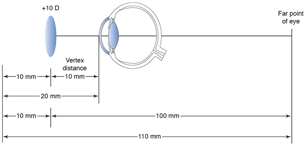
Figure 3-23 The importance of vertex distance in the correction of high refractive errors.
Cylindrical Correcting Lenses and the Far Point Concept
The far point principles used in the correction of hyperopia and myopia are also employed in the correction of astigmatism with spectacle lenses. However, in astigmatism, the required lens power must be determined separately for each of the 2 principal meridians.
Cylinders in spectacle lenses produce both monocular and binocular distortion. The primary cause is meridional aniseikonia—that is, unequal magnification of retinal images in the various meridians. Although aniseikonia may be corrected by iseikonic spectacles, such corrections may be complicated and expensive, and most practitioners prefer to prescribe cylinders according to their clinical judgment. Clinical experience also suggests that adult patients vary in their ability to tolerate distortion, whereas young children always adapt to their cylindrical corrections.
The following guidelines may prove helpful in prescribing astigmatic spectacle corrections:
- For children, prescribe the full astigmatic correction at the correct axis.
- For adults, try the full correction initially. Give the patient a “walking-around” trial with trial frames before prescribing, if appropriate. Inform the patient about the need for adaptation. To reduce distortion, use minus cylinder lenses (most lenses dispensed today are minus cylinder) and minimize vertex distance.
- Because spatial distortion from astigmatic spectacles is a binocular phenomenon, occlude 1 eye to verify that spatial distortion is the cause of the patient’s difficulty.
- If necessary, reduce distortion by rotating the axis of the cylinder toward 180° or 90° (or toward the old axis) and/or reduce the cylinder power. Adjust the sphere to maintain spherical equivalent, but rely on a final subjective check to obtain the most satisfactory visual result.
- If distortion cannot be reduced sufficiently, consider contact lenses or iseikonic corrections.
For a more detailed discussion of the problem of, and solutions for, spectacle correction of astigmatism, see Appendix 3.1 at the end of the chapter.
Prescribing for Children
The correction of ametropia in children presents several special and challenging problems. In adults, the correction of refractive errors has 1 measurable endpoint: the best-corrected visual acuity. Prescribing visual correction for children often has 2 goals: providing a focused retinal image and achieving the optimal balance between accommodation and convergence.
In some young patients, subjective refraction may be impossible or inappropriate, often because of the child’s inability to cooperate with subjective refraction techniques. In addition, the optimal refraction in infants or small children (particularly those with esotropia) requires the paralysis of accommodation with complete cycloplegia. In such cases, objective techniques such as retinoscopy are the best way to determine the refractive correction. Moreover, the presence of strabismus may require modification of the normal prescribing guidelines.
Myopia
There are 2 types of childhood myopia: congenital (usually high) myopia and developmental myopia, which usually manifests itself between the ages of 7 and 10 years. Developmental myopia is less severe and easier to manage because the patients are older and refraction is less difficult. However, both forms of myopia are progressive; frequent refractions (every 6–12 months) and periodic prescription changes are necessary. The following are general guidelines for correction of significant childhood myopia:
- Cycloplegic refractions are mandatory. In infants, children with esotropia, and children with very high myopia (>10.00 D), atropine refraction may be necessary if tropicamide or cyclopentolate fails to paralyze accommodation in the office.
- In general, the full refractive error, including cylinder, should be corrected. Young children tolerate cylinder well.
- Some ophthalmologists undercorrect myopia, and others use bifocal lenses with or without atropine, on the basis of the theory that accommodation hastens or increases the development of myopia. This topic remains controversial among ophthalmologists.
- Intentional undercorrection of a child’s myopic esotropia to decrease the angle of deviation is rarely tolerated.
- Intentional overcorrection of a myopic error (or undercorrection of a hyperopic error) may help control intermittent exodeviations. However, such overcorrection can cause additional accommodative stress.
- Parents should be educated about the natural progression of myopia and the need for frequent refractions and possible prescription changes.
- In older children, contact lenses may be desirable to avoid the problem of image minification that arises with high-minus lenses.
Stay updated, free articles. Join our Telegram channel

Full access? Get Clinical Tree


