CHAPTER 11 Overview of Diagnostic Imaging of the Head and Neck
The scope of head and neck imaging is too broad a topic to be covered in one chapter. The authors provide the clinician with an outline and brief synopsis of the field. Definitive textbooks for each area of head and neck imaging are available.1–4
Available Imaging Modalities
Conventional Radiography
Computed Tomography
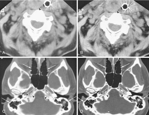
To create images from the attenuation values, CT uses complex mathematical reconstruction algorithms. Bone disease and bone trauma are best visualized with a bone detail algorithm whereas a soft tissue algorithm is used to evaluate soft tissue structures (Fig. 11-1).
Computed Tomography Image Display
Images from a given reconstruction algorithm can be displayed in various ways to highlight differences in attenuation of different structures. The window width refers to the range of attenuation values in HU that make up the gray scale for a given image. The window level refers to the center HU value for that given window width. A narrow window width of 80 HU and a level of 40 HU is frequently used for brain imaging because it centers the density at the common density of brain tissue, and displays only those densities 40 HU greater than and 40 HU less than the window level. Thus any density greater than 80 HU will be displayed as white, and any density less than 0 will be displayed as black on the gray scale. Any intermediate density will be spread out evenly along the gray scale. For imaging of the soft tissues of the head and neck, a window level of approximately 40 to 70 HU is usually chosen, at a midpoint approximately equal to the density of muscle. The window width frequently is in the 250 to 400 HU range, thus displaying a wider range of densities including calcification, intravenous contrast, muscle, and fat to best advantage. For imaging bony structures such as paranasal sinuses and temporal bone, window levels from 0 to 400 HU and a wide window width of 2000 to 4000 HU may be chosen. The reason for a wide bone window width is that a wide range of densities ranging from cortical bone (approximately +1000 HU) down to gas (−1000 HU) need to be displayed on the same image. However, structures of intermediate density between bone and gas occupy a narrow range on the gray scale at this window width and are poorly discriminated (appear washed out) on these settings. The terminology commonly used to describe the previously mentioned windows includes soft tissue windows (window width of 250 to 400 HU) and bone windows (2000 to 4000 HU). It is important to understand that these display windows are completely independent of the mathematical imaging algorithm chosen for creation of the image. In other words, an image created by a soft tissue algorithm can be displayed with soft tissue and bone window widths (see Figs. 11-1A and C). Conversely, the image may be computer reconstructed using a bone algorithm and displayed with either soft tissue or bone window width (see Fig. 11-1B and D). To optimize the imaging of the soft tissue lesion and the adjacent bone, a soft tissue and a bone algorithm may be used, generating images with the appropriate soft tissue and bone windows. (See also Figs. 11-12A and C).
Patient Cooperation
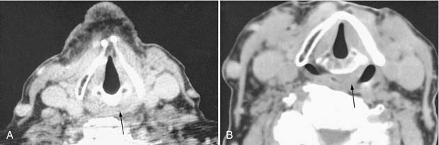
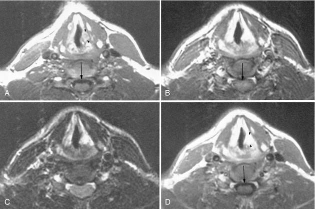
Patient cooperation is necessary to obtain optimal image quality. The patient is instructed not to swallow and to stop breathing or to maintain quiet breathing during each slice acquisition to minimize motion artifact from the adjacent airway and pharyngeal structures. Occasionally, provocative maneuvers such as blowing through a small straw or using a cheek-puffing (modified Valsalva) maneuver to distend the hypopharynx, or phonating to assess vocal cord movement, may be necessary (Figs. 11-2 and 11-3).
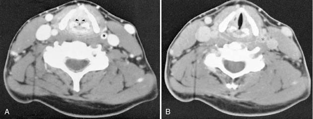
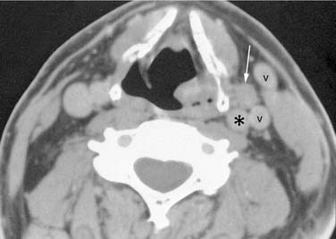
Contrast enhancement often is used to opacify blood vessels and to identify regions of abnormal tissue as identified by abnormal enhancement patterns (Fig. 11-4). As it relates to head and neck imaging, contrast is particularly useful in CT scans of the neck and orbits. Contrast often is not needed in evaluation of the temporal bones, although it can be necessary on occasion. CT of the facial bones and paranasal sinuses does not require intravenous contrast for most common applications.
Radiation Exposure
The effective dose equivalent was developed as a means of representing the fraction of the total stochastic risk of fatal cancers and chromosomal abnormalities resulting from the irradiation of a particular body part. A system of weighting is used to consider the individual susceptibility of the body’s major tissues and organs. A full discussion of this is beyond the scope of this chapter. Suffice to say that, for a given examination, the effective dose to the patient is less than the dose (radiation dose equivalent) received by the area under examination. Table 11-1 lists common radiologic procedures and their effective dose equivalents.
Table 11-1 Estimated Effective Dose Equivalent of Common Examinations
| Examination | Effective Dose Equivalent |
|---|---|
| Chest radiograph | 20 mrem |
| CT, abdomen | 1000 mrem |
| CT, chest | 1000 mrem |
| CT, brain | 120 mrem |
| CT, sinus | 70 to 130 mrem |
From Nationwide Evaluation of X-Ray Trends (NEXT) 2000 Survey of Computed Tomography. Frankfort, KY: Food and Drug Administration, Center for Devices and Radiological Health; August 2007. CRCPD Publication E-07-2.
Magnetic Resonance Imaging
Magnetic Resonance Imaging Artifacts
Motion artifact, chemical shift artifact, susceptibility artifacts from metallic implants (e.g., amalgam, orthodontic implants), and eyelid mascara degrade MRI (Fig. 11-5). Motion artifact becomes more prominent with increased field strength, increased length of individual pulse sequences, and the total length of the imaging study. A typical imaging sequence may last from 2 to 8 minutes. To limit motion artifact, sequences fewer than 4 minutes are preferred, and the patient should be instructed not to swallow and to breathe shallowly and quietly.
Magnetic Resonance Imaging Pulse Sequences
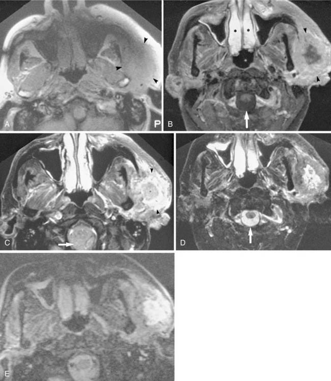
Numerous pulse sequences are available on clinical MRI units. The details of the physics of MRI may be found in most radiology and MRI textbooks. Commonly used imaging protocols include T1-weighted, spin (proton) density, T2-weighted, gadolinium-enhanced T1-weighted, fat-suppressed, and gradient echo imaging. Magnetic resonance angiography (MRA) is infrequently obtained (Figs. 11-6 and 11-7). The abbreviations used to identify sequence parameters are repetition time (TR), echo time (TE), and inversion time (TI) and are measured in milliseconds. The following description of pulse sequences is intended to assist the clinician in identifying and understanding the commonly performed sequences and in determining their respective use in the head and neck.
T1-Weighted Images
T1-weighted (short TR) sequences (see Figs. 11-6A and 11-7A) use a short TR (500 to 700 msec) and a short TE (15 to 40 msec). T1-weighted imaging is the fundamental head and neck sequence because it provides excellent soft tissue contrast with a superior display of anatomy, a high signal-to-noise ratio, and a moderate imaging time (4 to 5 min), minimizing motion artifacts. Fat is high signal intensity (bright or white) on T1WIs and provides natural contrast in the head and neck. Air, rapid blood flow, bone, and fluid-filled structures (e.g., vitreous and cerebrospinal fluid [CSF]) are low signal intensity (dark or black) on T1WIs. Muscle is low to intermediate in signal intensity on T1WIs. The inherent high contrast of fat relative to adjacent structures allows excellent delineation of the muscles, globe, blood vessels, and mass lesions that border on fat. The cortical bone is black, and the enclosed bone marrow is bright from fat within the marrow. The aerated paranasal sinuses are black, whereas retained mucous or mass lesions are of low to intermediate signal intensity. Most head and neck mass lesions show a comparable signal to muscles on T1WIs. (To quickly identify a T1WI: fat is white, CSF and vitreous are black, and nasal mucosa is low signal.)
T2-Weighted Images
T2-weighted images (see Fig. 11-6C) use a long TR (2000 to 4000 msec) and a long TE (50 to 90 msec) and are sometimes referred to as long TR/long TE images. Note that spin density and T2WI are acquired simultaneously from a single sequence that produces two sets of images with the same TR but different TEs. For example, spin density = 2000/30 and T2WI = 2000/80. T2WIs are most useful for highlighting pathologic lesions. T2WIs show the vitreous and CSF as high signal intensity (bright) relative to the low to intermediate signal intensity of head and neck fat and muscle. Fat loses signal intensity with increased T2 weighting. Most radiologists use a fast spin-echo (FSE) T2WI for head and neck imaging, which provides a much faster acquisition with improved signal-to-noise. Fat remains bright, however, on FSE images. Most head and neck masses are higher signal intensity on a T2WI compared with their low-to-intermediate signal intensity on T1WI. The combination of the T1WI and T2WI is often useful for characterizing fluid-containing structures, solid components, and hemorrhage. Bone, rapid vascular flow, calcium, hemosiderin, and air-containing sinuses are black. Inflammatory sinus disease and normal airway mucosa appear very bright. (To quickly identify a T2WI: CSF, vitreous, and nasal mucosa are bright. Muscle is low to intermediate in signal.)
Gadolinium Enhancement
Gadolinium-based contrast material is used in conjunction with T1WI sequences (gadolinium shortens the T1) and, with the dose used, it has little effect on T2WI. The advantages of contrast enhancement are increased lesion conspicuity and improved delineation of the margins of a mass relative to the lower signal of muscle, bone, vessel, or globe.5 However, gadolinium enhancement (without concomitant fat suppression) has had limited usefulness within the head and neck, as well as in the orbit, because of the large amount of fat present within these regions (see Fig. 11-6D). After gadolinium injection, the signal increases within a lesion, often obscuring the lesion within the adjacent high signal intensity fat.6 Therefore, for head and neck imaging, gadolinium is optimally used with specific fat suppression techniques that turn fat dark or black. Gadolinium enhances normal structures including nasal and pharyngeal mucosa, lymphoid tissue in Waldeyer’s ring, extraocular muscles, and slow-flowing blood in veins, all of which may appear surprisingly bright, especially if combined with fat suppression techniques. (To quickly identify a gadolinium-enhanced T1WI: nasal mucosa is white, fat is white, and CSF and vitreous are black. Also look for Gd-DTPA printed directly on the image or on adhesive study labels.)
Fat Suppression Methods
Gradient Echo Techniques
Numerous gradient echo sequences are available that have a variety of applications. Gradient echo scans have a very short TR (30 to 70 msec), a very short TE (5 to 15 msec), and a flip angle of less than 90 degrees. They have a variety of proprietary acronyms, including GRASS, MPGR, SPGR, FLASH, and FISP. Gradient echo sequences take advantage of the phenomenon of flow-related enhancement. That is, any rapidly flowing blood appears extremely bright. These sequences are useful for localizing normal vessels, detecting obstruction of flow in compressed or thrombosed vessels, and showing vascular lesions that have tubular, linear, or tortuous bright signal representing regions of rapid blood flow (Fig. 11-8). Gradient echo sequences may be obtained faster than conventional spin-echo techniques, although their increased susceptibility to motion artifact decreases the benefits of a short scan time. Gradient echo techniques also permit volume, that is, three-dimensional versus two-dimensional acquisition of images, allowing increased spatial resolution and computer workstation reconstruction of any imaging plane at various slice thicknesses. The disadvantage of gradient echo sequences is the increased magnetic susceptibility artifact from bone or air, thus limiting their role near the skull base or paranasal sinuses. (To quickly identify a gradient echo image: arteries and often veins are white; fat, CSF, vitreous, and mucosa may have variable signal intensities depending on the technique used.)
Nuclear Medicine
Radionuclide Imaging
Techniques of thyroid imaging and thyroid therapy are described in several textbooks.9,10 Many centers use I-123 to obtain a thyroid update determination, and 99mTc-pertechnetate is used to obtain whole gland images. It is these images that determine whether thyroid nodules are “hot” or “cold.” I-131 is used for therapy of hyperthyroidism and in follow-up to detect and treat residual, recurrent, and metastatic thyroid cancers.
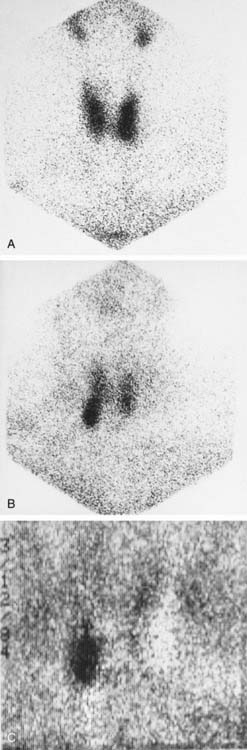
Identification of parathyroid adenomas has been done for several years with a subtraction technique using 99mTc-pertechnetate and Tl-201 (Fig. 11-9). The basis of this test is that thallium is taken up by thyroid tissue and parathyroid tissue. Thyroid tissue is the only tissue that uptakes 99mTc-pertechnetate. Therefore the subtraction of the 99mTc-pertechnetate image from the thallium-201 image should leave only parathyroid tissue. The sensitivity of this technique is believed to be very high for lesions larger than 1 g. Sensitivity decreases for smaller lesions, and the subtraction technique can be hampered by patient motion. 99mTc-sestamibi is now the favored agent in many institutions. A double-phase imaging protocol is employed with improved identification of parathyroid adenomas.
CSF leaks can be detected with In-111 DTPA placed into the subarachnoid space. This technique is described and illustrated in Chapter 44.
Three-Dimensional Reconstruction Techniques
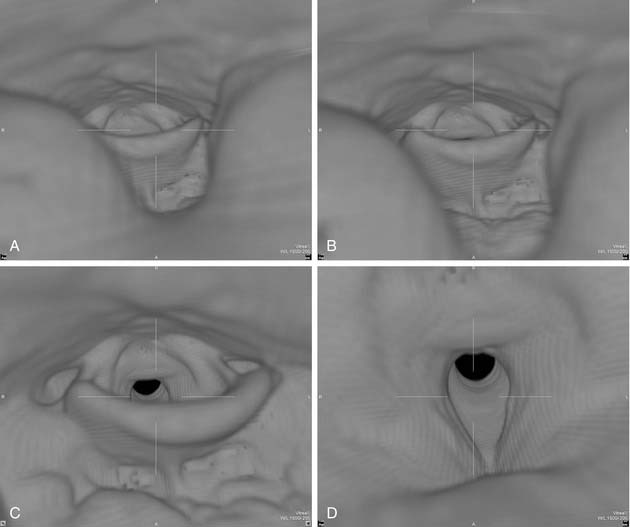
The utility of three-dimensional reconstruction is best appreciated with craniofacial reconstructions.11,12 Directly visualizing the three-dimensional relationships of the facial structures aids surgical planning. Instructors find three-dimensional models of the face and orbital structures useful for teaching medical students, residents, and anatomy students. Virtual endoscopy is a computer-generated simulation of endoscopic perspective. The virtual endoscopic images of the trachea, larynx, pharynx, nasal cavity, and paranasal sinuses and ear have demonstrated clinical utility (Fig. 11-10).
Applications of CT, MRI, and Ultrasound in the Head and Neck
Application of Computed Tomography in Head and Neck Region
Multichannel CT scanners revolutionized head and neck imaging. The entire neck can be scanned in less than a minute at a slice thickness of less than 1 mm. These data can then be reconstructed in any plane with a desired slice thickness. This obviated the need for site specific imaging protocols. A typical neck CT using a multidetector scanner employs 1-mm slice thickness and a pitch of approximately 1, with contiguous axial scanning performed from the sella turcica down to the thoracic inlet. Then, typically 3-mm-thick axial, sagittal, and coronal images are reconstructed for view. The use of intravenous contrast is critical for interpretation of the study. Determination of extent of disease and vascular invasion, compression, and discrimination of vessels from nodes and small muscle bundles can be extremely difficult (see Figs. 11-3 and 11-4). Evaluation of the normal mucosa-submucosa interface and mucosal tumors can not be accomplished without contrast enhancement. Optimally, contrast should be present in both arteries and veins during image acquisition. Also, enough contrast should be allowed to diffuse from vessels to the tissue interstitium for tumors to enhance. This is particularly important for high-end multidetector CT scanners, which tend to finish image acquisition before optimal tumor enhancement is achieved, unless a delay between injection of contrast and scanning is employed. To maintain good opacification of vessels after this delay, a biphasic contrast injection scheme is used. The delay time and the rate at which contrast material is injected vary depending on the specifications of the scanner. Contrast is best administered with a mechanical pump infusion although a drip-infusion technique may also be effective. Frequently, image reconstruction using a soft tissue algorithm suffices. If a suspicion of bone erosion or destruction by tumor or inflammation exists, sections of the skull base and mandible need to be reconstructed using a bone algorithm.
Suprahyoid Neck
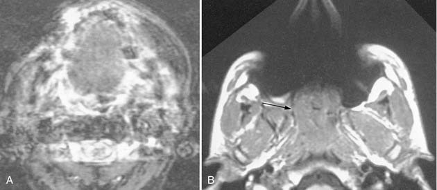
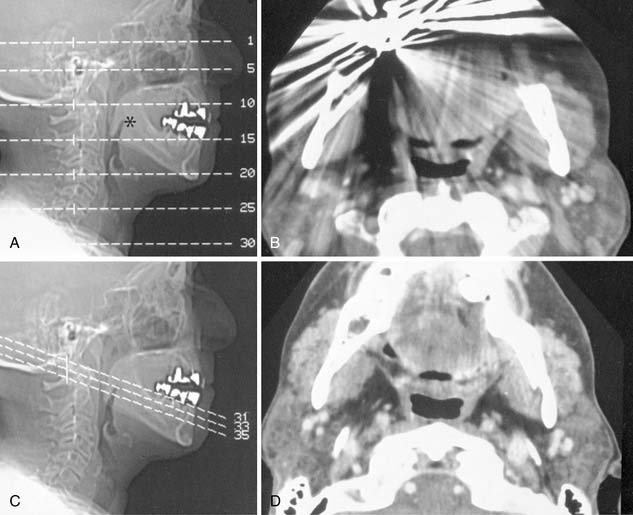
Suprahyoid neck CT is often performed for simultaneous evaluation of the deep extent of mucosal based tumors and to evaluate associated metastatic disease to the cervical lymph node chains. Because streak artifacts from dental fillings frequently obscure the oropharynx and nasopharynx, it is usually necessary to obtain additional angled sections to assess the pharynx directly posterior to the dental work (Fig. 11-11).
Salivary Glands
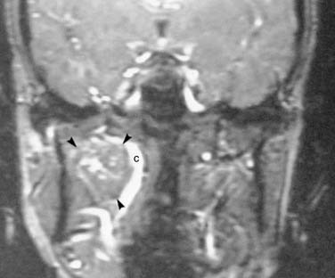
Dental amalgam can cause significant streak artifacts that obscure the parotid or submandibular gland parenchyma. If the dental work is identified on the lateral scout view (scanogram), dental artifacts can usually be avoided if an oblique semiaxial projection is chosen with the scanner gantry angled in a negative direction (between a coronal and an axial plane), thus avoiding the teeth. This plane has the advantage of visualizing both parotid and submandibular glands in the same slice and is parallel to the posterior belly of the digastric muscle.13 Contrast administration is required for both neoplastic and inflammatory conditions of the salivary glands. Enhancing intraglandular vessels may mimic or obscure small stones, thus a precontrast scan is also advised in cases of suspected sialolithiasis. The CT attenuation of a normal parotid gland is variable depending on the proportion of fat and glandular tissue present, which varies with age. Submandibular glands have a more predictable attenuation that is similar to that of muscle. Any difference in attenuation values of the right and the left submandibular glands should be suspicious for an obstructing lesion such as floor of the mouth cancer.
Sialography and CT-Sialography
Conventional sialography, although rarely needed, remains the best radiographic method for evaluating ductal anatomy in obstructive, inflammatory, and autoimmune salivary gland diseases. Supplemental CT-sialography may be performed in evaluation of a dense gland that is suspected to harbor a mass in patients who cannot have MRI. CT-sialography may be obtained at the time of intraductal injection of fat-soluble or water-soluble contrast or after a routine sialogram (the gland may be reinjected during the CT with the catheter left in place). The plane of study is the same as that used for NCCT and should be similarly angled to avoid dental filling artifacts. The use of concentrated sialographic contrast material may cause significant streak artifacts if too much contrast collects in dilated ducts, acini, or large pools, all of which can obscure smaller masses in the gland. For optimal CTS, the injection is extended into the acinar phase to maximize parenchymal opacification and thereby silhouette mass lesions within the parenchyma.14
Larynx and Infrahyoid Neck
Laryngeal and infrahyoid neck CT is most commonly requested to evaluate squamous cell carcinoma of the larynx or hypopharynx, associated cervical lymph node metastasis, trauma, and inflammation. The fine detail of the larynx and vocal cords requires thinner reconstructions than the routine 3-mm sections. Sections through the vocal cords are optimally reconstructed parallel to the plane of the true vocal cords. Because assessment of vocal cord mobility is important in staging glottic carcinoma, various provocative techniques may facilitate laryngeal imaging in those cases where the vocal cords are obscured on physical examination. Quiet breathing places the cords in a partially abducted position. By having the patient blow through a straw or do a modified Valsalva maneuver (puffing out the cheeks) the hypopharynx and supraglottic larynx can be distended, allowing better separation of the aryepiglottic folds from the hypopharynx, while simultaneously abducting the cords (see Fig. 11-3). The vocal cords can be assessed during phonation (“eeee”), which causes the cords to adduct and move to a paramedian position (see Fig. 11-3). Breath holding will also adduct the vocal cords, close the glottis, and significantly reduce motion artifacts. By scanning the larynx twice, once to adduct and a second time (sections limited to the glottis) to abduct the vocal cords, the radiologist can assess vocal cord motion and identify fixation. Evaluation of laryngeal trauma may not require intravenous contrast. Bone windows are helpful for assessing cartilage fractures or tumor erosion.
Paranasal Sinuses
Paranasal sinus CT can be approached in several ways depending on the anticipated disease process. A screening axial sinus NCCT (Fig. 11-12A) is clearly superior to conventional radiographs and provides information on specific sinus involvement by inflammatory processes as well as better delineation of bony sclerosis or destruction. One method is to use 5-mm-thick sections obtained at 10-mm intervals (5-mm gap), which can cover the entire paranasal sinuses with six to eight slices. The technical parameters can be optimized to achieve a low radiation exposure that is similar to radiographs.
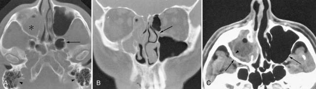
When endoscopic sinus surgery is anticipated, NCCT imaging of the sinuses is mandatory for preoperative evaluation of the extent of sinus disease, to detect anatomic variants, and for planning the surgical approach (see Fig. 11-12B). This study is done in the axial plane while the patient is supine with thin sections reconstructed in sagittal and coronal planes. Frequently, only the bone algorithm with its edge enhancement properties is needed for evaluating the detailed anatomy of the ostiomeatal complex. Contrast administration is usually not necessary for routine sinusitis, although when severe nasal polyposis is suspected, contrast may be useful to demonstrate the characteristic “cascading” appearance of the enhancing polyps or to characterize an associated mucocele. A soft tissue algorithm with soft tissue windows may be useful when using CECT for intracranial complications from sinus inflammatory processes. A nasal decongestant may be used to help decrease normal but asymmetrical nasal mucosa congestion (normal nasal mucosal cycle) from a mucosal based mass.
The assessment of sinus tumors requires the most detailed imaging. The intracranial compartment, parapharyngeal, masticator, and buccal spaces should sufficiently be included in the field-of-view as to allow for assessment of tumor extension. At least the lymph node levels I and II should be visualized. For an optimal study, both soft tissue and bone algorithms are used. This differentiates the soft tissue component, as well as evaluating subtle bony destruction (see Figs. 11-12A and C). The coronal plane is best for evaluating the cribriform plate. CECT is used to maximize the enhancement characteristics of the tumor and differentiate it from adjacent soft tissue structures.


