4 Translabyrinthine Approaches
 Basic Translabyrinthine Approach (Figs. 4.1–4.47)
Indications
• Removal of cerebellopontine angle lesions when hearing preservation is not a concern, as follows:
(a) Acoustic neurinoma:
–With unserviceable preoperative hearing whatever the size of the tumor is. It should be noted that giant tumors can be safely removed through this approach.
–Acoustic neurinoma more than 1.5 cm in the extrameatal diameter irrespective of the preoperative hearing.
(b) Meningiomas, posterior to or centered on the internal auditory canal, with unserviceable hearing. Cases that lie anterior to the canal require a transapical extension, whereas large petroclival tumors need a modified transcochlear approach.
(c) Other cerebellopontine angle tumors with unserviceable hearing, such as epidermoids, dermoids, etc.
• Vertigo surgery:
–Labyrinthectomy
–Vestibular neurectomy
Surgical Steps
1. An extended mastoidectomy is performed. The middle fossa dura and the sigmoid sinus are identified, leaving a thin shell of bone over them. Bone 2–3 cm posterior to the sinus is drilled using a large cutting burr. The middle fossa dura is beveled. The sinodural angle is widely opened.
2. The mastoid air cells are exenterated, and the antrum is widely opened.
3. The digastric ridge is identified at its anterior border. The ridge points directly to the mastoid segment of facial nerve at the area of the stylomastoid foramen. The facial nerve is only skeletonized, and not uncovered.
4. Once the facial nerve has been identified, retrofacial air cells can be safely drilled, and the sigmoid sinus is followed to the jugular bulb.
5. Using a large diamond burr, the last shell of bone covering the sigmoid sinus and the dura posterior the sigmoid sinus is removed. The sigmoid sinus is gently depressed using the suction irrigation tube, and the posterior fossa dura in front of the sinus is separated from the overlying bone using a large septal dissector. Bone is then drilled using a large cutting burr.
6. When the level of the posterior semicircular canal is reached, the endolymphatic sac is seen passing from its position medial to the sac to enter between the layers of the dura. The duct maintains the posterior fossa dura attached to the labyrinth. Using a Beaver knife with the sharp edge directed against the bone, the duct is cut away, enabling further retraction of the posterior fossa dura.
7. Bone over the middle fossa dura is also removed using a rongeur after it has been separated from the dura. Care is taken to leave a thin shell of bone adjacent to the labyrinth in order to protect the posterior and middle fossa dura while carrying out the labyrinthectomy.
8. The labyrinthectomy starts by opening the lateral semicircular canal using a medium-sized cutting burr. The posterior semicircular canal is next opened, followed by the opening of the superior semicircular canal. The labyrinthectomy continues by drilling off the three semicircular canals.
9. Care is taken to leave the anterior lateral part of the lateral semicircular canal, in order to protect the part of facial nerve lying within the concavity of the canal. The medial wall of the ampullae of the superior and lateral semicircular canals is also left, to protect the labyrinthine segment of the facial nerve and to serve as a landmark for the superior ampullary nerve as well as the upper limit of the internal auditory canal (IAC).
10. The vestibule is now widely opened. It is important to avoid drilling the floor of the vestibule, in order to avoid entering the fundus of the internal auditory canal. The facial nerve runs immediately lateral to the vestibule, and over zealous drilling of the roof of the vestibule would therefore injure the nerve. Drilling in this area should be from superior to inferior or vice versa, and never from medial to lateral, in order to prevent injury to the fundus or the facial nerve.
11. After completion of the labyrinthectomy, the bone left over the posterior and middle fossa dura is successively reduced. Using a large septal dissector, the dura is separated from the bone which is then removed using a rongeur. Following the posterior fossa dura leads to identification of the IAC porus.
12. Identification of the inferior and superior borders of the internal auditory canal begins. During this process, drilling should be carried out parallel to the canal and in a medial to lateral direction. The ampulla of the superior semicircular canal serves as a landmark for the superior border of the IAC.
13. The inferior border of the canal is identified by drilling the retrofacial air cells between the jugular bulb inferiorly and the presumed level of the canal superiorly. At this level, drilling identifies the cochlear aqueduct. This is an important landmark for the glossopharyngeal nerve, which lies immediately inferior and medial to it. In live surgery, opening the cochlear aqueduct leads to cerebrospinal fluid (CSF) leakage, thereby reducing intradural tension.
14. Bone between the middle fossa dura and the superior border of the IAC is further drilled. Care is taken while doing this to avoid injury to the facial nerve (FN) or dura.
15. Bone at the level of the porus is further reduced by careful drilling in semicircles starting superior to the IAC, coursing posteriorly and ending inferior to it. Once this bone has been thinned out, it can be separated from the underlying internal auditory canal dura using a dissector.
16. The dura of the internal auditory canal is now completely exposed. Two troughs have been created superiorly and inferiorly to the internal auditory canal, and the canal is exposed over 270° of its circumference.
17. The posterior aspect of the internal auditory canal at the level of the fundus is drilled inferiorly. This exposes the inferior vestibular nerve. Further drilling at a more superior level identifies the transverse crest, which separates the inferior from the superior vestibular nerve. The superior vestibular nerve is followed laterally where it leaves the fundus of the IAC and enters a tiny canal that carries the nerve, which is now called the superior ampullary nerve, to the ampulla of the lateral semicircular canal (LSC).
18. The inferior ampullary nerve is detached from the fundus using a hook. With the tip of the hook facing inferiorly, the superior ampullary nerve is detached from its canal. While this step is being carried out, Bill’s bar lies anterior to the superior ampullary nerve, protecting the anteriorly lying FN from injury during this maneuver. With the help of a Brackmann suction tip, the hook is used to continue detaching the superior vestibular nerve, separating it from the FN and reflecting it medially. The FN can now be clearly seen entering the intralabyrinthine canal, and the extent of its involvement by the tumor can be assessed.
19. In live surgery, the lines of incision undergo bipolar coagulation before the posterior fossa dura is opened, in order to avoid bleeding.
20. The superior dural incision runs parallel and inferior to the superior petrosal sinus up to the limits of bony drilling. The inferior incision starts just in front of the distal part of the sigmoid sinus and follows the sinus and jugular bulb course to the porus, where it joins the superior incision. The dura of the IAC is next opened. The canal dura at the level of the porus is incised using scissors.
21. At the end of the approach, a double-curved hook is used to remove the incus through the aditus. The middle ear is then packed with periosteum in order to prevent cerebrospinal fluid leakage.
Hints and Pitfalls
• Extensive removal of bone over the middle fossa dura and posterior to the sigmoid sinus, uncovering the posterior fossa dura, is a fundamental step for obtaining a wide approach adequate for tumor removal, in comparison with the classic translabyrinthine approach.
• The sigmoid sinus has to be completely uncovered. Leaving an island of bone over the sigmoid sinus (Bill’s island) limits the degree of sinus retraction. The edges of the bone island may injure the sinus wall during retraction.
• Bone between the terminal part of the sigmoid sinus and the jugular bulb should be removed to allow optimal visualization of the lower portion of the cerebellopontine angle. Removing the bone here is a tedious job, and it should be done with care to avoid injuring the fragile jugular bulb.
• The attachment of the endolymphatic sac to the posterior fossa dura impedes posterior retraction of the latter. For this reason, a blade is used to incise the proximal part of the sac, with the tip directed against the bone.
• The facial nerve lies immediately lateral to the vestibule. The utmost care should be taken to avoid injuring the nerve during drilling to open the vestibule. At this level, drilling should be posterior and never medial to the nerve.
• The internal auditory canal should be uncovered over 270° rather than only 180° of its circumference.
• A thin shell of bone left covering the internal auditory canal until all the drilling around has been completed helps prevent injury to the contents of the canal from the rotating drill in case it should slip.
• The original technique described by House for identifying the facial nerve at the fundus depends on identification of the vertical crest (Bill’s bar). This is a constant landmark that separates the facial nerve, located anterosuperiorly, from the superior vestibular nerve, located posteriorly. The only disadvantage of this technique is that it carries a potential risk of injury to the facial nerve, particularly in inexperienced hands. In our practice, we use the horizontal crest and the superior ampullary nerve to identify the facial nerve (as described above), and we no longer use House’s method, except in the very rare cases when there is doubt regarding the position of the facial nerve.
• Care should be taken while removing the incus to avoid fracturing the footplate, since this can create a communication between the cerebellopontine angle and the middle ear, with subsequent postoperative CSF leakage. The footplate can be protected by placing a small rightangled pick medial to the long process of the incus and distracting in a posterolateral direction.
• Use periosteum rather than fat for the closure of the attic. Periosteum is easier to manipulate, and provides a better seal.
• Do not displace the jugular bulb inferiorly if it was the only bulb or the predominant sinus. The angio-magnetic resonance image should be examined first in order to be sure of the adequacy of the contralateral circulation.
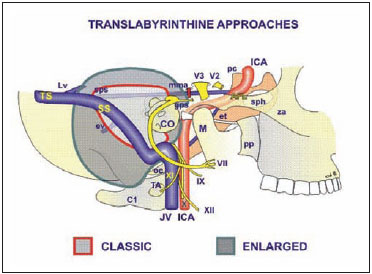
Fig. 4.1 The structures controlled by the translabyrinthine approach. The shaded area within the red line signifies the extent of exposure achieved by the classical translabyrinthine approach, while the green line shows the extent of exposure achieved by the enlarged translabyrinthine approach. VII Facial nerve, IX Glossopharyngeal nerve, X Vagus nerve, XI Accessory nerve, XII Hypoglossal nerve, AFL Anterior foramen lacerum, C1 Atlas, CO Cochlea, et Eustachian tube, ev Emissary vein, gps Greater superficial petrosal nerve, ICAInternal carotid artery, JV Jugular vein, Lv Labbe vein, M Mandible, mma Middle meningeal artery, oc Occipital condyle, pc Posterior clinoid, pp Pterygoid process, sphSphenoid sinus, spsSuperior petrosal sinus, SSSigmoid sinus, TA Lateral process of the atlas, TS Transverse sinus, V2 2nd division of the trigeminal nerve, V3 3rd division of the trigeminal nerve, za Zygomatic arch
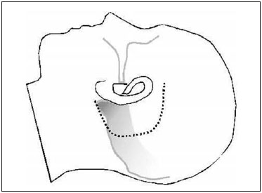
Fig. 4.2 The skin incision is made as shown.
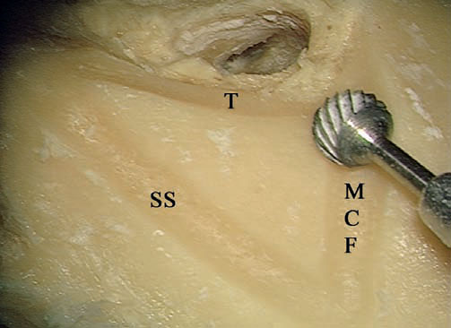
Fig. 4.3 In a left temporal bone, the triangle of attack is created. MCF Level of the middle cranial fossa, SS Level of the sigmoid sinus, T Tangent to the posterior canal wall
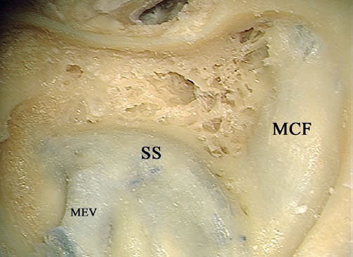
Fig. 4.4 The extended mastoidectomy has been performed. MCF Middle cranial fossa, MEV Mastoid emissary vein, SS Sigmoid sinus
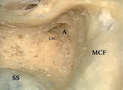
Fig. 4.5 The antrum (A) has been opened. The short process of the incus (*) and the lateral semicircular canal (LSC) are the landmarks for the genu of the facial nerve. MCF Middle cranial fossa, SS Sigmoid sinus
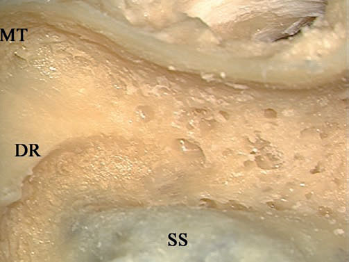
Fig. 4.6 The digastric ridge has been identified. DR Digastric ridge, MT Mastoid tip, SS Sigmoid sinus
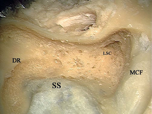
Fig. 4.7 The mastoid segment of the facial nerve between the lateral semicircular canal (LSC) and the digastric ridge (DR) is to be skeletonized. MCF Middle cranial fossa, SS Sigmoid sinus
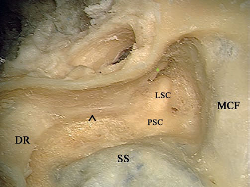
Fig. 4.8 The mastoid segment of the facial nerve (^) has been well skeletonized. * Short process of the incus, DR Digastric ridge, LSC Lateral semicircular canal, MCF Middle cranial fossa, PSC Posterior semicircular canal, SS Sigmoid sinus
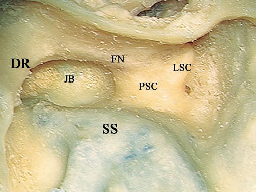
Fig. 4.9 The jugular bulb (JB) has been identified medial to the mastoid segment of the facial nerve (FN). DR Digastric ridge, LSC Lateral semicircular canal, PSC Posterior semicircular canal, SS Sigmoid sinus
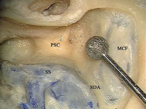
Fig. 4.10 A large diamond burr is used to thin down the bone overlying the sigmoid sinus and the dura into a thin shell. MCF Middle cranial fossa, PSC Posterior semicircular canal, SDA Sinodural angle, SS Sigmoid sinus
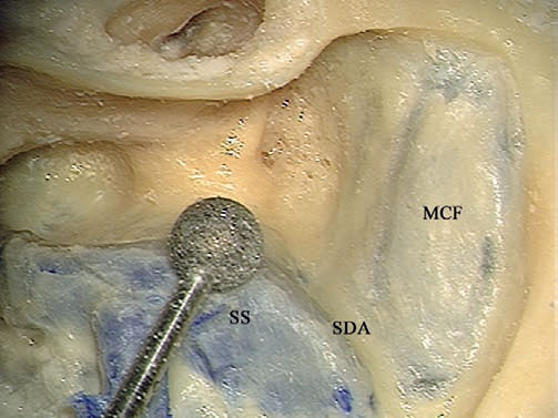
Fig. 4.11 The direction of movement of the burr should be parallel to the structures being skeletonized—the sigmoid sinus (SS) here. MCF Middle cranial fossa, SDA Sinodural angle
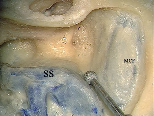
Fig. 4.12 A small diamond burr should be moved from medial to lateral while thinning the bone in the sinodural angle. MCF Middle cranial fossa, SS Sigmoid sinus
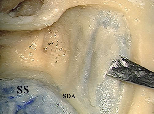
Fig. 4.13 A septal raspatory is used to remove the last shell of bone. SDA Sinodural angle, SS Sigmoid sinus
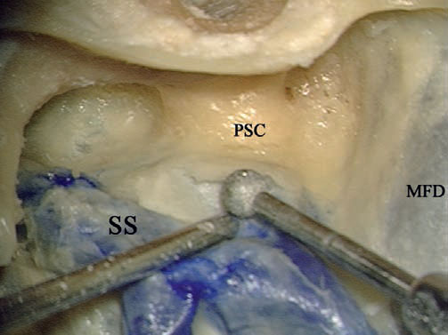
Fig. 4.14 The suction tip is used to retract the dura and sigmoid sinus (SS), while a diamond burr is used the remove the remaining bone. MFD Middle fossa dura, PSC Posterior semicircular canal
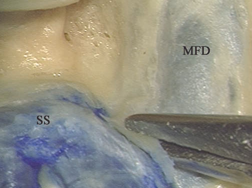
Fig. 4.15 Using a rongeur, the bone at the sinodural angle is removed. MFD Middle fossa dura, SS Sigmoid sinus
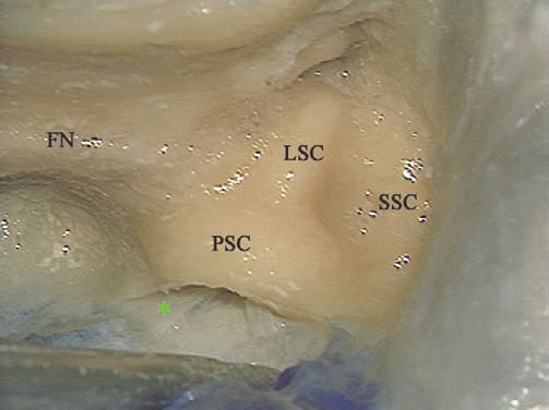
Fig.4.16 The endolymphatic duct (*) can be seen extending from a position medial to the posterior semicircular canal (PSC) to the posterior fossa dura, preventing adequate retraction. FN Facial nerve, LSC Lateral semicircular canal, SSC Superior semicircular canal
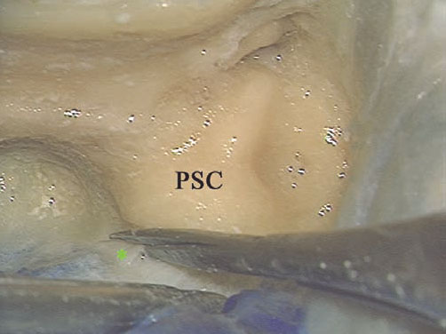
Fig.4.17 The endolymphatic duct (*) is sharply cut. PSC Posterior semicircular canal
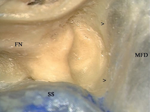
Fig. 4.18 The arrows point to the bone left to protect the dura while labyrinthectomy is being performed. FN Facial nerve, MFD Middle fossa dura, SS Sigmoid sinus
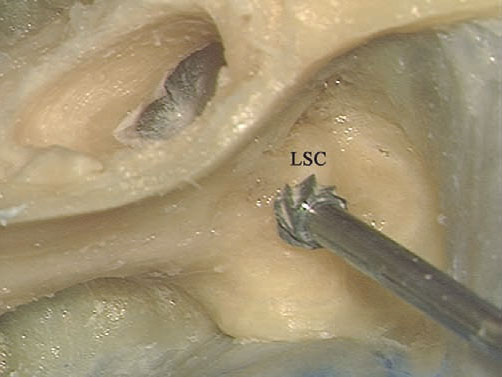
Fig. 4.19 A cutting burr is used to open the labyrinth, starting with the lateral semicircular canal (LSC).
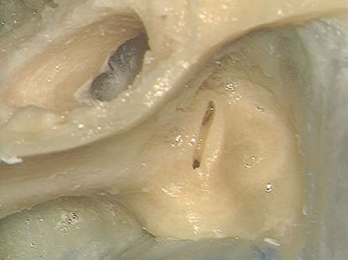
Fig. 4.20 The lateral semicircular canal has been opened.
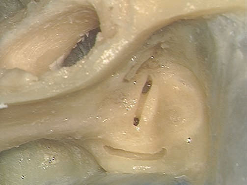
Fig. 4.21 The posterior canal is opened.
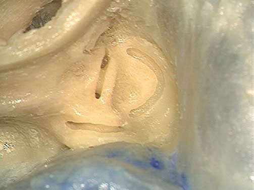
Fig. 4.22 The superior canal is opened.
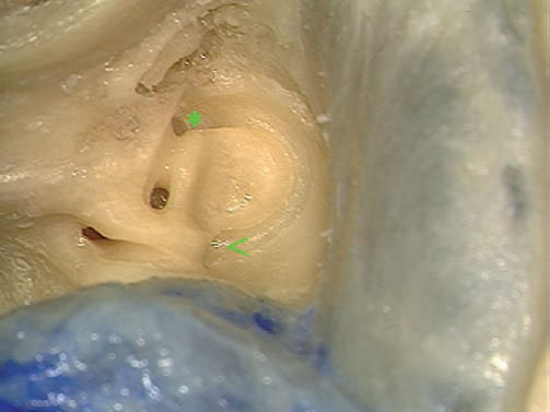
Fig. 4.23 The openings of the canals into the vestibule. < Common crus, * The joint lateral and superior ampullae
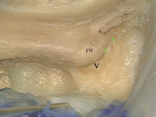
Fig. 4.24 The canals have been drilled away, and the vestibule (V) has been opened. Note the thin amount of bone (<) separating the genu of the facial nerve (FN) from the vestibule. *: The part of the superior canal ampulla left as a landmark to the superior edge of the internal auditory canal.
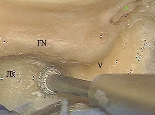
Fig. 4.25 Identification of the lower edge of the internal auditory canal starts by drilling the bone between the jugular bulb (JB) and the expected position of the canal. * Incus, FN Facial nerve, V Vestibule
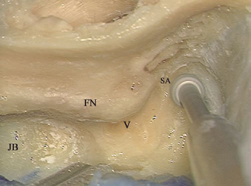
Fig. 4.26 The ampulla of the superior canal (SA) serves as a landmark to the superior edge of the internal auditory canal. The drill should be moved from medial to lateral. FN Facial nerve, JB Jugular bulb, V Vestibule
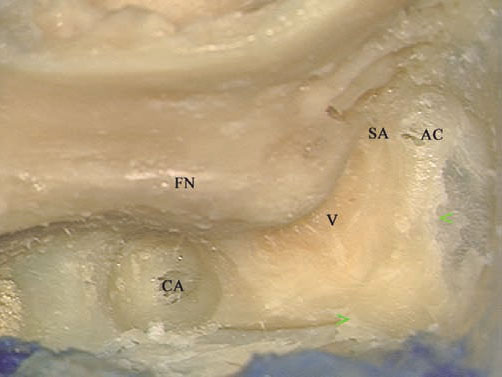
Fig. 4.27 Note the bone (< >) left to protect the dura from the drill. AC Supralabyrinthine air cells, CACochlear aqueduct, FN Facial nerve, SA Ampulla of the superior canal, V Vestibule
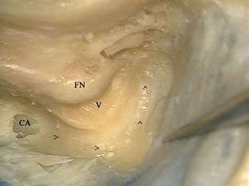
Fig. 4.28 The arrows indicate the direction of the movement of the drill when looking for the internal auditory canal, in a semicircular fashion. * Superior ampulla, CA Cochlear aqueduct, FN Facial nerve, V Vestibule
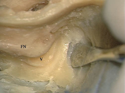
Fig. 4.29 Separating the dura from the drilled bone helps avoid injury to it and leads to early identification of the meatus of the internal auditory canal. FN Facial nerve, V Vestibule
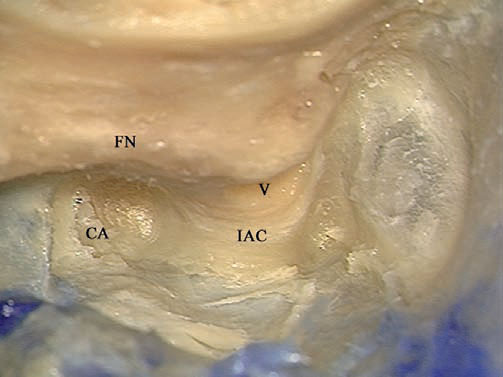
Fig. 4.30 The internal auditory canal (IAC) has been identified, but the overlying bone needs to be thinned further. CA Cochlear aqueduct, FN Facial nerve, V Vestibule
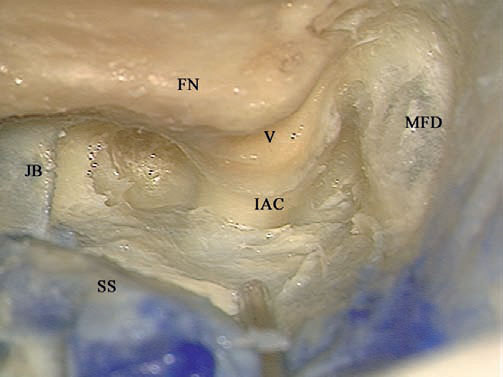
Fig. 4.31 The internal auditory canal (IAC) has been adequately skeletonized. FN Facial nerve, JB Jugular bulb, MFD Middle fossa dura, SS Sig moid sinus, V Vestibule
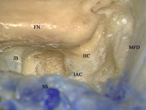
Fig. 4.32 The last shell of bone covering the internal auditory canal (IAC) has been removed using a hook. Note that the sigmoid sinus (SS) lies anteriorly, covering the view of the canal, and should be retracted posteriorly by the suction tube. FN Facial nerve, HC Horizontal crest, JB Jugular bulb, MFD Middle fossa dura
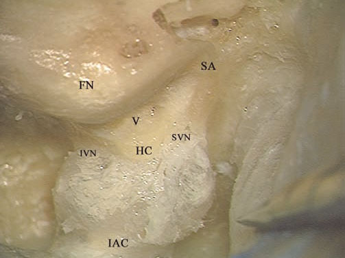
Fig. 4.33 The view of the fully exposed internal auditory canal (IAC). FN Facial nerve, HC Horizontal crest, IVN Inferior vestibular nerve, SA Superior ampulla, SVN Superior vestibular nerve, V Vestibule
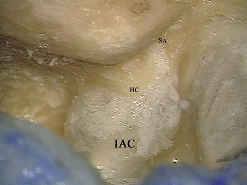
Fig. 4.34 The superior ampullary nerve canal (SA) has been identified. HC Horizontal crest, IAC Internal auditory canal
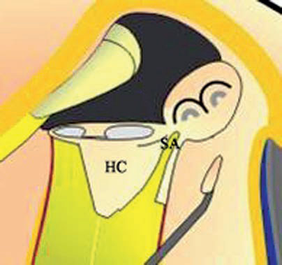
Fig. 4.35a
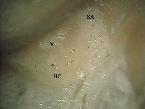
Fig. 4.35a, b The superior ampullary nerve and its canal (SA) at higher magnification. HC Horizontal crest, V Vestibule
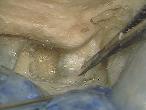
Fig. 4.36 The dura of the internal auditory canal is being opened.
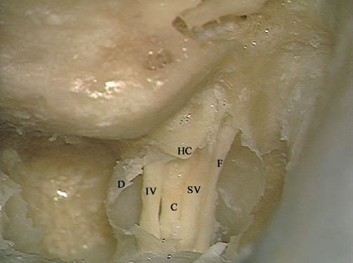
Fig. 4.37 The contents of the canal can be seen. C Cochlear nerve, D Dura of the canal, F Facial nerve, HC Horizontal crest, IV Inferior vestibular nerve, SV Superior vestibular nerve
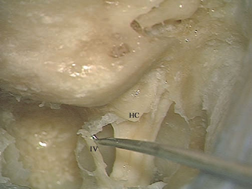
Fig. 4.38 The inferior vestibular nerve (IV) has been detached. HC Horizontal Crest
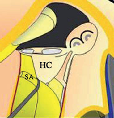
Fig. 4.39a
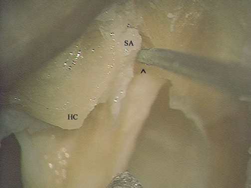
Fig. 4.39a,b A hook is used to detach the superior ampullary nerve (SA) from its canal. Bill’s bar (^) can be seen lying anterior to the hook, protecting the labyrinthine segment of the facial nerve. HC Horizontal crest
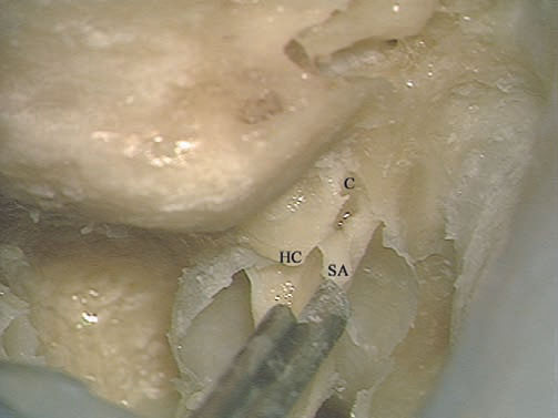
Fig. 4.40 The superior ampullary nerve (SA) has been completely detached from its canal (C). HC Horizontal crest
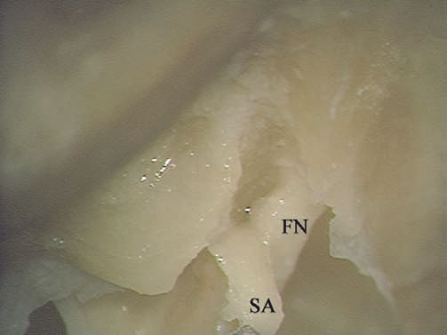
Fig. 4.41 At higher magnification, the relationship between the facial nerve (FN) and the superior ampullary nerve (SA) can be better appreciated.
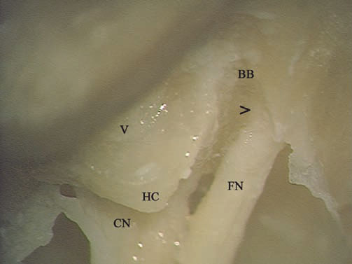
Fig. 4.42 The view of the fundus after removal of the vestibular nerve. > The beginning of the labyrinthine segment of the facial nerve, BB Bill’s bar, CN Cochlear nerve, FN Facial nerve in the internal auditory canal, HC Horizontal crest, V Vestibule
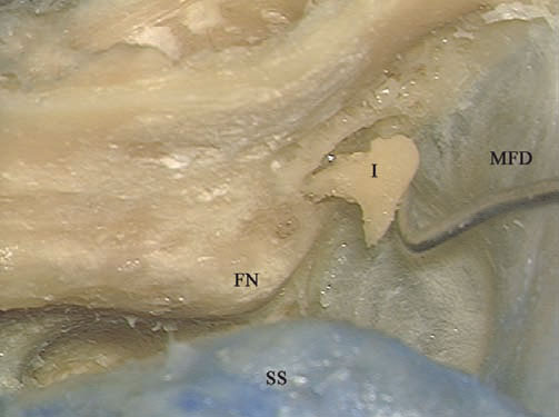
Fig. 4.43 At the end of the approach, the incus (I) is removed through the antrum. FN Facial nerve, MFD Middle fossa dura, SS Sigmoid sinus
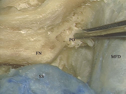
Fig. 4.44 In live surgery, periosteum (PO) is used to fill the middle ear cleft, to prevent cerebrospinal fluid leakage. FN Facial nerve, MFD Middle fossa dura, SS Sigmoid sinus
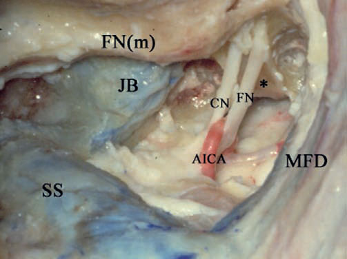
Fig. 4.45 A left-sided cadaveric dissection to show the intracranial structures. * Anterior wall of the internal auditory canal, AICA Anterior inferior cerebellar artery, CN Cochlear nerve, FN Facial nerve, FN(m) Mastoid segment of the intracranial nerve, JB Jugular bulb, MFD Middle fossa dura, SS Sigmoid sinus
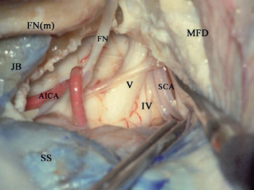
Fig. 4.46 This case shows the benefit of uncovering the dura. The uncovered middle fossa dura (MFD) can be retracted superiorly here to demonstrate the routes of the trigeminal nerve (V), trochlear nerve (IV), and superior cerebellar artery (SCA). AICA Anterior inferior cerebellar artery, FN Facial nerve, FN(m) Mastoid segment of the facial nerve. JB Jugular bulb, SS Sigmoid sinus
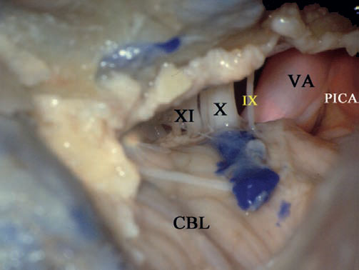
Fig. 4.47 This image shows the benefit of uncovering the sigmoid sinus, the dura posterior to it, and of adequate removal of the bone between the sigmoid sinus and jugular bulb. After these steps have been carried out, the posterior inferior cerebellar artery (PICA), vertebral artery (VA), glossopharyngeal nerve (IX), vagus nerve (X), and accessory nerve (XI) can all be controlled in the lower part of the approach. CBL Cerebellum
 Management of High Jugular Bulb (Figs. 4.48–4.60)
A high jugular bulb is present in about 25% of cases. Particularly in medium-sized or large tumors, a high bulb may obstruct the required view of the area of the lower cranial nerves. In these cases, the high jugular bulb is managed as follows.
Surgical Steps
1. Using a septal elevator, the bulb, together with the surrounding periosteal layer, is dissected from its wall. This should be done very carefully to avoid injury to the thin bulb wall.
2. After adequate dissection has been carried out, the jugular bulb is pressed downward using a large piece of Surgicel overits dome. Surgicel helps control the bleeding that may occur during this step.
3. A piece of bone wax is then placed over the Surgicel to keep the bulb in place. Note that a thin layer of bone must be left around the jugular bulb to support the Surgicel and bone wax.
4. In some cases when there is a high jugular bulb, complete uncovering of the bulb dome (particularly anteriorly) may be difficult to achieve. In this case, the bulb lies anterior to the plane of the facial nerve, and the vertical distance between the bulb and the nerve is very small. In such cases, a large septal dissector cannot be used to dissect the bulb from its walls. Alternatively, a double-curved raspatory can be used. The bulb is managed as described previously.
5. With adequate inferior displacement of the jugular bulb, sufficient bone removal can be safely carried out, creating a bony trough inferior to the internal auditory canal.
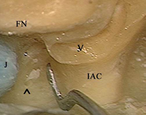
Fig. 4.48 Labyrinthectomy and skeletonization of the internal auditory canal have been carried out. Note the narrow distance available between the high jugular bulb (J) and the internal auditory canal (IAC). ^ Cochlear aqueduct, FN Facial nerve, V Vestibule
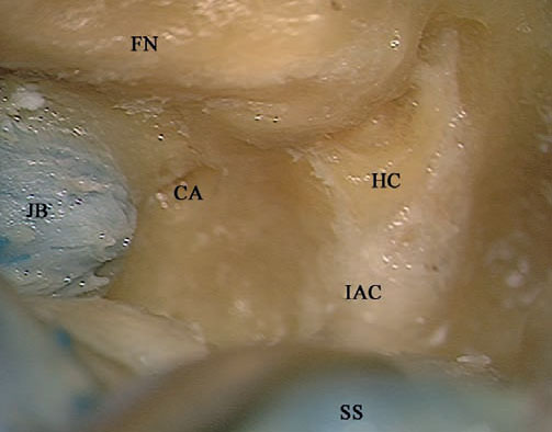
Fig. 4.49 The last shell of bone over the internal auditory canal (IAC) has been removed. CA Cochlear aqueduct, FN Facial nerve, HC Horizontal crest, JB Jugular bulb, SS Sigmoid sinus
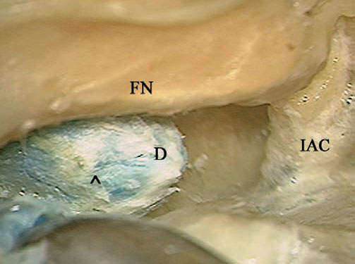
Fig. 4.50 The dome of the jugular bulb (D) has been exposed by carefully removing the overlying bone to the level of the arrow (^). FN Facial nerve, IAC Internal auditory canal
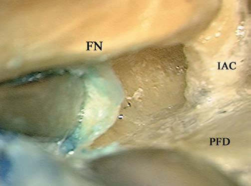
Fig. 4.51 A septal raspatory is carefully used to dissect the jugular bulb from the anteriorly lying bone. FN Facial nerve, IAC Internal auditory canal, PFD Posterior fossa dura
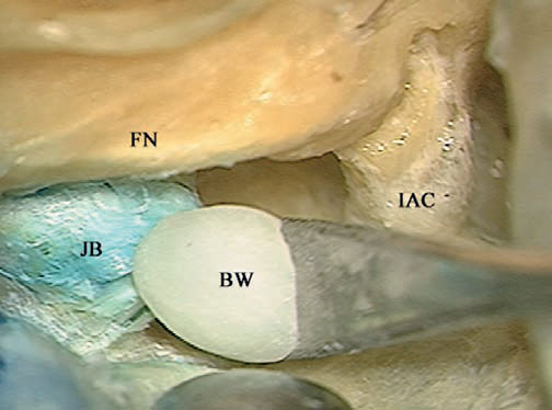
Fig. 4.52 Bone wax (BW) is used to fix the jugular bulb (JB) in its lowered position. FN Facial nerve, IAC Internal auditory canal
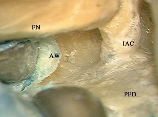
Fig. 4.53 The septal raspatory is used to further push down the bone wax to secure it in place. The extent of lowering should not lead to closure of the bulb. FN Facial nerve, IAC Internal auditory canal, PFD Posterior fossa dura
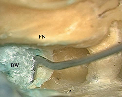
Fig. 4.54 The bone wax (BW) can be seen fixing the bulb in its lowered position. FN Facial nerve
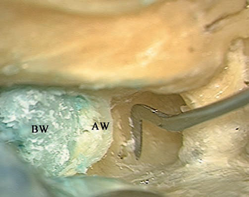
Fig. 4.55 The anterior wall (AW) of the jugular bulb should now be drilled away to widen the surgical field. BW Bone wax
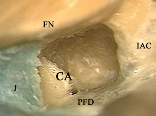
Fig. 4.56 The view after the procedure has been completed. The space gained is less than 1 cm, but this space is considered to be extremely useful in skull base surgery. CA Cochlear aqueduct, FN Facial nerve, IAC Internal auditory canal, J Jugular bulb, PFD Posterior fossa dura
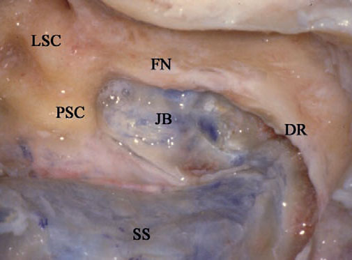
Fig. 4.57 Another case of high jugular bulb in a right translabyrinthine approach. In this case, an extended mastoidectomy has been carried out and the dura has been uncovered. The jugular bulb (JB) can be seen reaching high enough to touch the posterior semicircular canal (PSC). DR Digastric ridge, FN Mastoid segment of the facial nerve, LSC Lateral semicircular canal, SS Sigmoid sinus
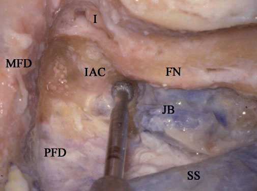
Fig. 4.58 The labyrinth has been drilled out, and the internal auditory canal (IAC) has been identified. Drilling is being carried out in the narrow area between the internal auditory canal and the jugular bulb (JB) to ex pose the dome of the bulb. FN Facial nerve, I Incus, MFD Middle fossa dura, PFD Posterior fossa dura, SS Sigmoid sinus
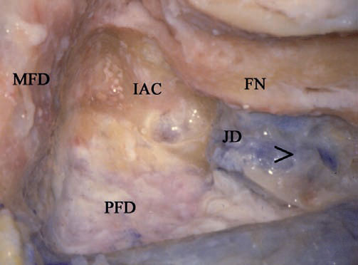
Fig. 4.59 The dome of the jugular bulb (JD) has been exposed up to the level shown by the arrow (>). FN Facial nerve, IAC Internal auditory canal, MFD Middle fossa dura, PFD Posterior fossa dura
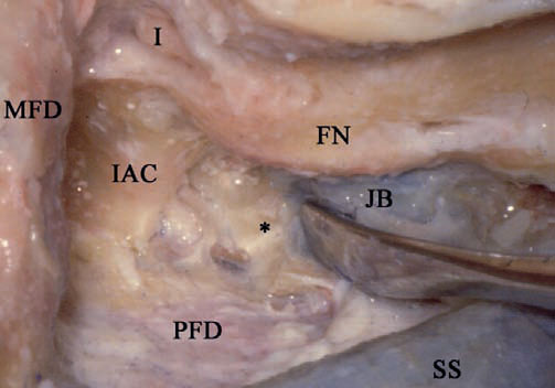
Fig. 4.60 The jugular bulb (JB) has been dissected from the surround ing bone (*) and its height has been reduced. FN Facial nerve, I Incus, IAC Internal auditory canal, MFD Middle fossa dura, PFD Posterior fossa dura, SS Sigmoid sinus
 The Enlarged Translabyrinthine Approach with Transapical Extension Types (I & II) (Figs. 4.61–4.73)
Rationale
This approach is an anterior extension of the enlarged translabyrinthine approach, in which the internal auditory canal is drilled for 320° or 360° of its circumference (types I & II, respectively).
Indications
The approach is indicated for large cerebellopontine angle tumors in which hearing preservation is not intended, as follows:
• Large and giant acoustic neurinomas with anterior extension into the prepontine cisterns (type I approach).
• Large meningioma of the posterior surface of the temporal bone centered on the internal auditory canal with significant anterior extension (type II approach).
• Small tumors with marked anterior extension.
• Cases of contracted mastoid.
Surgical Steps
1. The extended mastoidectomy is performed as previously described. Wide bone removal is carried out, exposing approximately 3 cm of the middle fossa dura and the retrosigmoid posterior fossa dura. The sigmoid sinus is completely uncovered.
2. Labyrinthectomy is performed.
3. The internal auditory canal is identified and uncovered. Bone is removed for 270° around the canal, as previously described.
4. Bone is further removed inferior to and superior to the internal auditory canal, toward the petrous apex. The whole contents of the internal auditory canal are pushed inferiorly to allow drilling of the anterior wall of the canal.
5. At the end of the procedure, 360° of the internal auditory canal circumference is exposed (type II approach). In the type I approach, it is only necessary to remove 320° of the circumference of the canal.
Hints and Pitfalls
• Transapical drilling should be done with a diamond burr, with extreme care being taken not to injure the facial nerve. A useful trick is to place the suction irrigation tube between the drill and the nerve to provide protection.
• Care should be taken while drilling the petrous apex superior to the internal auditory canal so as not to injure the superior petrosal sinus.
• In giant tumors causing high intracranial pressure, the dura usually bulges, hindering access. In such cases, the dura can be opened first to allow drainage of CSF, with a resultant release of pressure and shrinkage of the dura. The drilling can then be continued.
• Particularly in tumors that lie in a far anterior position, the facial nerve is markedly displaced anteriorly. The transapical extension allows much better visualization of the nerve where it starts to curve.
• This approach also allows better control of the trigeminal nerve up to Meckel’s cave, and of the abducent nerve, prepontine cistern, and basilar artery.
• Using this approach, we have abandoned the transotic approach for anteriorly located tumors and limit its use only to cases of concomitant cochlear invasion or vertical internal carotid artery involvement.
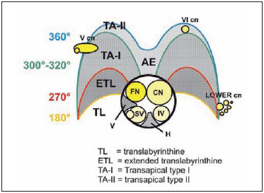
Fig. 4.61 The extent of drilling around the internal auditory canal needed to achieve the extensions of the translabyrinthine approach. AE Anterior wall of the internal auditory canal, CN Cranial nerve, FN Facial nerve, H Horizontal crest, IV Inferior vestibular nerve, Lower cn Lower cranial nerve, SV Superior vestibular nerve, V Vertical crest, V cn Fifth cranial nerve (trigeminal nerve), VI cn Sixth cranial nerve (abducent nerve)
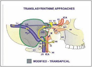
Fig. 4.62 The structures exposed by the translabyrinthine-transapical approach. The gray-shaded area indicates the extent of bone removal. Note the transapical extension. See Fig. 4.1, p. 57, for key to abbreviation.
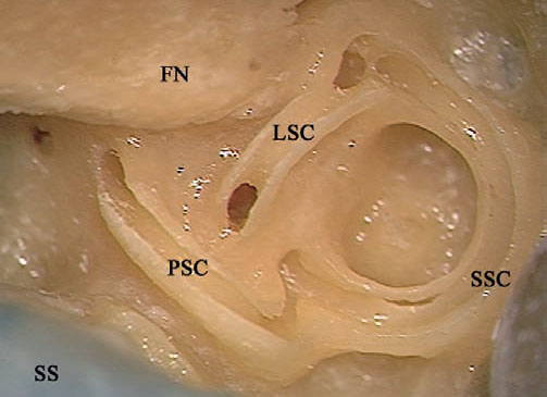
Fig.4.63 The lateral (LSC), posterior (PSC), and superior (SSC) semi circular canals have been opened in a left temporal bone. FN Facial nerve, SS Sigmoid sinus
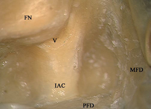
Fig. 4.64 The internal auditory canal (IAC) has been skeletonized over 270°. FN Facial nerve, MFD Middle fossa dura, V Vestibule
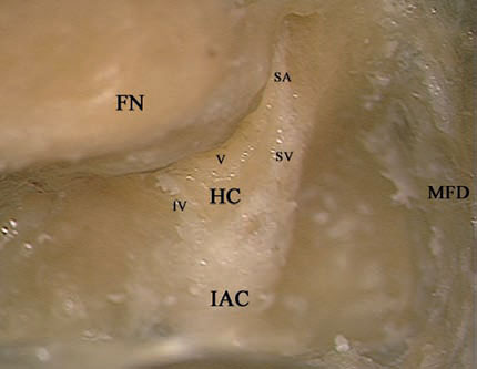
Fig. 4.65 The last shell of bone covering the internal auditory canal (IAC) has been removed. FN Facial nerve, HC Horizontal crest, IV Inferior vestibular nerve, MFD Middle fossa dura, SA Superior ampullary nerve, SV Superior vestibular nerve, V Vestibule
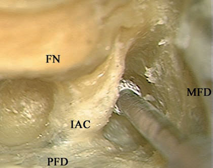
Fig. 4.66 To achieve a type I transapical extension, 320° of the bone surrounding the internal auditory canal (IAC) should be removed. The Superior ampullary nerve, superior part of the bone removal has been carried out here, as can be seen from the part of the burr head covered by the canal. FN Facial nerve, MFD Middle fossa dura, PFD Posterior fossa dura
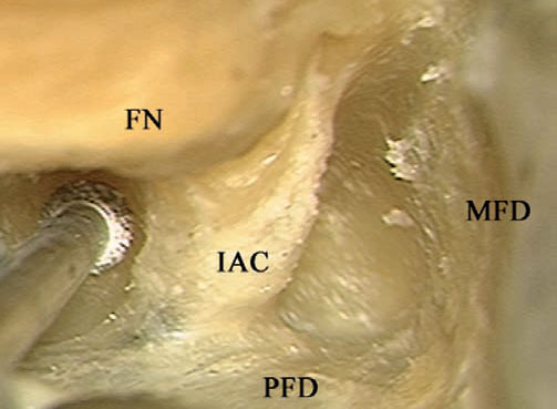
Fig. 4. 67 Drilling is now being carried out inferior to the internal auditory canal (IAC) to achieve a type I transapical extension (320 °). FN Facial nerve, MFD Middle fossa dura, PFD Posterior fossa dura
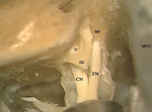
Fig. 4.68 The internal auditory canal has been opened and the vestibular nerves have been removed. BB Bill’s bar, CN Cochlear nerve, FN Facial nerve, HC Horizontal crest, MFD Middle fossa dura, V Vestibule
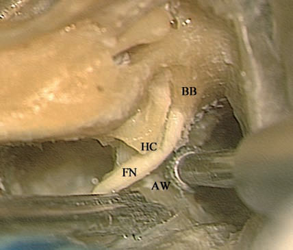
Fig. 4.69 The type II transapical extension involves drilling of all the bone surrounding the internal auditory canal (360°). To achieve this, the contents of the canal should be gently retracted using the suction tip, and the anterior wall of the internal auditory canal (AW) should be carefully drilled using a diamond burr. BB Bill’s bar, FN Facial nerve, HC Horizontal crest
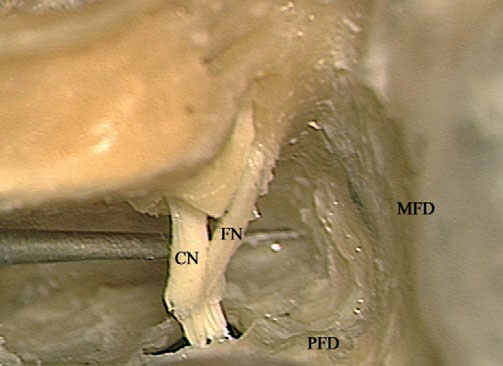
Fig. 4.70 A type II transapical extension has been completed. CN Cochlear nerve, FN Facial nerve, MFD Middle fossa dura, PFD Posterior fossa dura
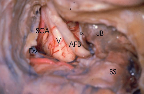
Fig. 4.71 A case of cadaveric dissection on the right side, illustrating the extent of the intradural structures that can be controlled using a translabyrinthine approach with a transapical extension. Here the approach has been completed and the dura has been opened. The trigeminal nerve (V) is clearly visible. IX Glossopharyngeal nerve, AFB Acousticofacial bundle, DV Dandy’s vein, JB Jugular bulb, SCA Superior cerebellar artery, SS Sigmoid sinus
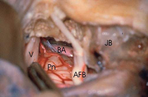
Fig. 4.72 The trigeminal nerve (V) can be seen here as it enters Meckel’s cave, and the basilar artery (BA) can be seen anterior to the pons (Pn). AFB Acousticofacial bundle, JB Jugular bulb
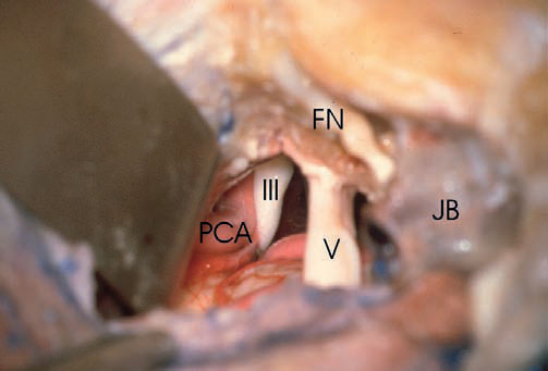
Fig. 4.73 In the superior part of the approach, retraction of the tentorium allows visualization of oculomotor nerve (III),and the posterior cerebral artery (PCA) can be seen. V Trigeminal nerve, FN Facial nerve, JB Jugular bulb
 Translabyrinthine Facial Nerve Decompression (Figs. 4.74–4.78)
Facial nerve decompression via the translabyrinthine approach is carried out whenever decompression of the full length of the facial nerve is required in the absence of useful hearing. The procedure is practically a combination of closed tympanoplasty with the translabyrinthine approach. Decompression of the mastoid, tympanic segments, and the geniculate ganglion parts of the facial nerve is achieved through the closed tympanoplasty. Labyrinthectomy and exposure of the internal auditory canal allows decompression of the tympanic and internal auditory canal parts of the nerve.
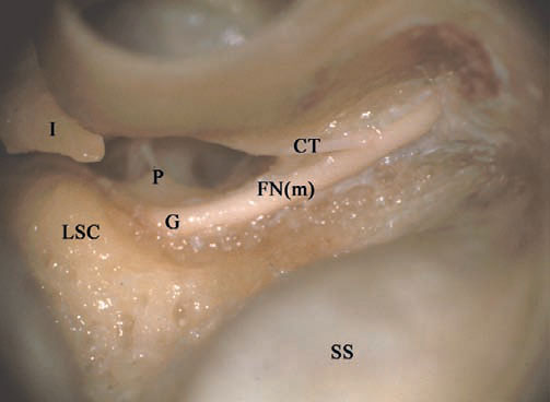
Fig. 4.74 A closed tympanoplasty and extended posterior tympanotomy have been carried out in a right temporal bone. The mastoid segment of the facial nerve (FNm) has been well skeletonized. CT Chorda tympani, G Genu, I Incus, LSC Lateral semicircular canal, P Pyramidal process, SS Sigmoid sinus
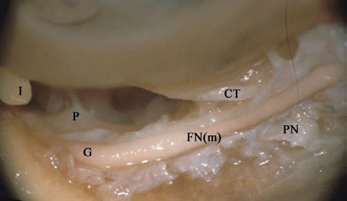
Fig. 4.75 The perineural sheath (PN) of the mastoid segment of the facial nerve (FNm) has been opened. CT Chorda tympani, G Genu, I Incus, P Pyramidal process
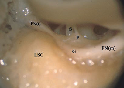
Fig. 4.76 Through the atticotomy, decompression of the tympanic segment of the facial nerve (FNt) is carried out. FN(m) Mastoid segment of the facial nerve, G Genu, LSC Lateral semicircular canal, P Pyramidal process, S Stapes
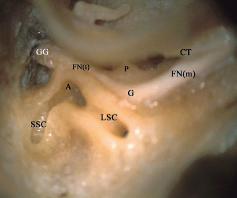
Fig. 4.77 Labyrinthectomy has been started. The joint ampulla (A) of the lateral (LSC) and superior (SSC) semicircular canals can be seen, closely related to the tympanic segment of the facial nerve (FNt). CT Chorda tympani, FN(m) Mastoid segment of the facial nerve, G Genu, GG Geniculate ganglion, P Pyramidal process
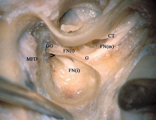
Fig. 4.78 Decompression of the whole course of the facial nerve has been achieved. > Labyrinthine segment of the facial nerve, CT Chorda tympani, FN(i) Internal auditory canal segment of the facial nerve, FN(m) Mastoid segment of the facial nerve, FN(t) Tympanic segment of the facial nerve, G Genu, GG Geniculate ganglion, MFD Middle fossa dura
< div class='tao-gold-member'>


