5 Middle Cranial Fossa Approaches
 Basic Middle Cranial Fossa Approach (Figs. 5.1–5.34)
Indication
This approach is indicated for pathologies that present with preoperatively preserved hearing in the following manner:
• Facial nerve decompression (simple middle cranial fossa approach)
The following pathologies are indications for the enlarged middle cranial fossa approach:
• Small vestibular schwannomas reaching the fundus of the internal auditory canal with a cerebellopontine angle extension of less than 0.5 cm
• Facial nerve tumors involving the nerve between the geniculate ganglion and internal auditory canal
• Supralabyrinthine petrous bone cholesteatoma not eroding the labyrinth
Surgical Steps
1. An ample quadrangular craniotomy measuring 4 × 5 cm is made. The craniotome is generally used for this step; however, if the instrument is not available, the craniotomy can be carried out using a drill. Craniotomy is started using a medium-sized cutting burr, and when the dura begins to show through the transparency of the bone, the burr is exchanged for a small diamond one. The lower edge of the craniotomy should be at the level of the base of the zygoma in order to be approximately at the level of the floor of the middle cranial fossa. The craniotomy should lie two-thirds in front and one-third behind the external auditory canal.
2. The bone flap is then separated from the underlying dura using a septal raspatory. Care should be taken during this step so as not to injure the dura.
3. Elevation of the dura from the superior surface of the temporal bone is now started under microscopic magnification. Dural elevation should progress carefully from lateral to medial and from posterior to anterior. The importance of careful dural elevation can not be overemphasized in live surgery, because of the risk of injury to the facial nerve (FN) caused by stretching the greater superficial petrosal nerve or injuring the geniculate ganglion (GG), which is dehiscent in 10–15% of cases.
4. While the procedure progresses, the following landmarks should be identified: the arcuate eminence, the middle meningeal artery, the greater superficial petrosal nerve, and the GG if dehiscent.
5. The medial limit of dural elevation should reach up to the border of the ridge of the petrous bone, which corresponds to the level of the superior petrosal sinus.
6. As dural elevation progresses, the middle fossa retractor is used to retract the dura, providing the necessary working space. The position of the retractor is changed to correspond to the point at which dural elevation is taking place. In its final position, the tip of the retractor should be lodged between the superior petrosal sinus and the border of the petrous bone. The middle meningeal artery forming the anterior limit of exposure should be kept intact.
7. At this point, the next step depends on the extent of the tumor. In tumors limited to the internal auditory canal (IAC), with or without limited extension to the cerebellopontine angle (CPA) as in vestibular schwannomas, the bone drilling should uncover the IAC from the porus to the fundus. The position of the internal auditory canal is indicated by a line bisecting the angle formed by the arcuate eminence and the greater superficial petrosal nerve.
8. Four different methods are available for identifying the internal auditory canal. The House method (Fig. 5.13) puts the facial nerve at risk, and requires the utmost care and skill, while the major disadvantages of the Fisch method (Fig. 5.14) are the variable angle between the superior semicircular canal and the internal auditory canal and the need to blue-line the superior semicircular canal, with the risk of opening it. The method we use identifies the canal at the bisection of the greater superficial petrosal nerve and superior semicircular canal, as proposed by Garcia-Ibanez (1980) (Fig. 5.15); however, we start drilling medially (Fig. 5.16) at the level of the porus.
9. Identification the IAC is started medially at the expected level of the porus of the IAC near the superior petrosal sinus. A large diamond drill is used, and drilling is carried out carefully at and around the predicted level of the porus.
10. Once the canal has been identified, bone removal should be continued until wide exposure of the dura has been achieved both anterior and posterior to the IAC, leaving only a thin shell of bone.
11. Drilling is now continued laterally to identify the full length of the internal auditory canal. In order to avoid injury to IAC, the drill should be moved in a direction parallel to the IAC and never crossing its longitudinal axis. Note that the exposure of the canal laterally is less than what can be achieved medially. This is due to the presence of the cochlea and vestibule respectively anterior and posterior to the lateral half of the internal auditory canal.
12. Once the whole length of the IAC has been identified, the last shell of bone covering the canal and the dura is removed. In live surgery, a small hole is created in the posterior fossa dura posterior to the IAC to allow for cerebrospinal fluid (CSF) escape, thus reducing the tension within the dura and improving exposure.
13. A small diamond burr is used to identify Bill’s bar at the level of the fundus. The level of exposure achieved up to thispoint is sufficient to remove tumors situated within the IAC.
14. Using a pair of microscissors, the dura of the internal auditory canal is opened. In live surgery, the suction tube must be exchanged at this step for a Brackmann’s suction.
15. The tumor usually originates from the inferior vestibular nerve, pushing the facial nerve superiorly and putting it at greater risk. The superior vestibular nerve is first dislocated using a small hook, and the tumor is then dealt with carefully so as not to injure the facial nerve lying between the surgeon and the tumor.
Hints and Pitfalls
• The craniotomy should be placed at the level of the root of the zygoma. This will reduce the amount of temporal lobe retraction.
• If air cells were opened either anteriorly at the level of the root of the zygoma or posteriorly at the level of the supramastoid crest, bone wax should be used to close them carefully to avoid CSF leakage.
• The dural elevation should reach medially to the level of the superior petrosal sinus. Failure to do this can lead to more lateral drilling, jeopardizing vital structures.
• Identification of Bill’s bar at the level of the fundus is important for positive identification of the facial nerve.
• The internal auditory canal dura is opened posteriorly in order to avoid injuring the anteriorly lying facial nerve.
• In a few cases, the loop of the anterior inferior cerebellar artery may be encountered within the canal. The utmost care must be taken to avoid injuring it.
Reference
Garcia-Ibanez E, Garcia-Ibanez JL. Middle fossa vestibular neurectomy: a report of 373 cases. Otolaryngol Head Neck Surg 1980;88:486–90.
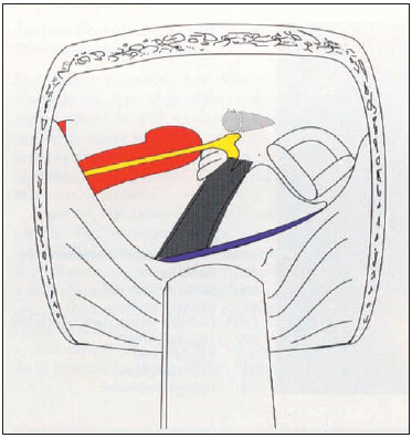
Fig. 5.1a The gray color represents the amount of petrous bone removal using the simple middle cranial fossa approach. Note that only the bone overlying the internal auditory canal is removed.
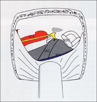
Fig. 5.1b The gray color represets the amount of petrous bone removal using the enlarged middle cranial fossa approach. IAC internal auditory canal, ICA internal carotid artery, SPS Superior petrasol sinus, SSC Superior semicircular canal
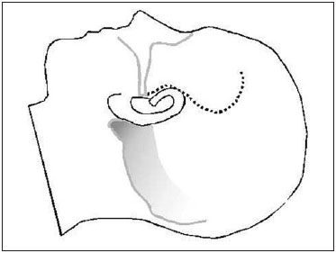
Fig. 5.2 The skin incision is made as shown.
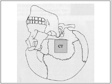
Fig. 5.3 The site of the craniotomy (CT) carried out for the middle cranial fossa approach.
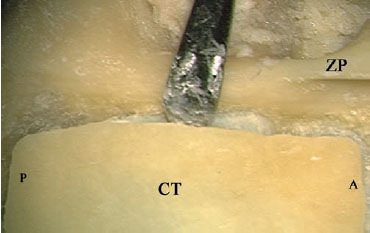
Fig. 5.4 After the craniotomy flap (CT) has been created in a left temporal bone, a septal raspatory is carefully used to separate the bony flap from the middle fossa dura. A Anterior, P Posterior, ZP Base of the zygomatic process
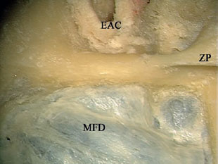
Fig. 5.5 The craniotomy is successfully elevated from the middle fossa dura (MFD). EAC External auditory canal, ZP Base of the zygomatic process
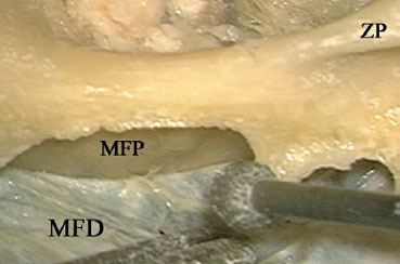
Fig. 5.6 The sharp bony edges are smoothed using a diamond burr while the middle fossa dura (MFD) is being retracted using the suction tube. MFP Middle fossa plate, ZP Base of the zygomatic process
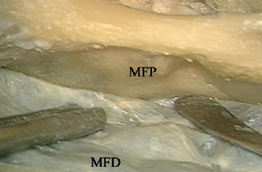
Fig. 5.7 Elevation of the middle fossa dura (MFD) from the middle fossa plate (MFP).
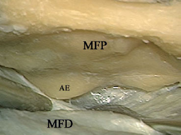
Fig. 5.8 The first landmark to be identified is the arcuate eminence (AE). MFD Middle fossa dura,MFP Middle fossa plate
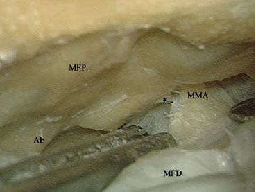
Fig. 5.9 As dural elevation advances anteriorly, the middle meningeal artery (MMA) is identified next.AE Arcuate eminence, MFD Middle fossa dura, MFP Middle fossa plate
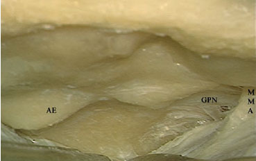
Fig. 5.10 The greater petrosal nerve (GPN) is identified next. AE Arcuate eminence, MMA Middle meningeal artery
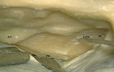
Fig. 5.11 The middle fossa retractor is fixed at the petrous ridge (PR). AE Arcuate eminence, GPN Greater petrosal nerve, M Middle meningeal artery
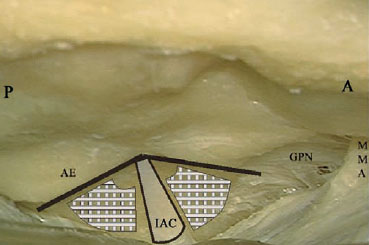
Fig. 5.12 The expected location of the internal auditory canal (IAC). The bar-shaded areas are the locations for drilling. A Anterior, AE Arcuate eminence, GPN Greater petrosal nerve, MMA Middle meningeal artery, P Posterior
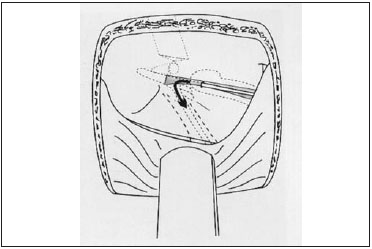
Fig. 5.13 House’s method of identifying the internal auditory canal.
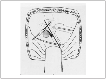
Fig. 5.14 Fisch’s method of identifying the internal auditory canal.
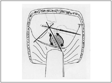
Fig. 5.15 Garcia-Ibanez’s method of identifying the internal auditory canal.
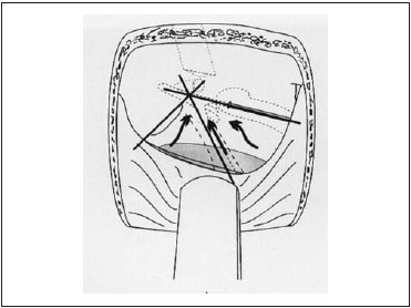
Fig. 5.16 Sanna’s method of identifying the internal auditory canal.
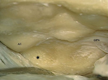
Fig. 5.17 Identification of the internal auditory canal is started by drilling between the arcuate eminence (AE) and the expected level of the internal auditory meatus (*) using a large burr. GPN Greater petrosal nerve
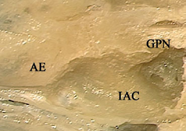
Fig. 5.18 A closer view shows that the location of the internal auditory canal (IAC) has been identified.AE Arcuate eminence, GPN Greater petrosal nerve
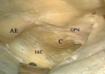
Fig. 5.19 The dura of the internal auditory canal (IAC) can be seen through the thin bone covering. The arcuate eminence (AE) and the cochlea (C) have been well skeletonized to gain the maximum space. GPN Greater petrosal nerve
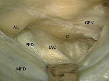
Fig. 5.20 Further drilling identifies the posterior fossa dura (PFD) under the thin bone covering. AE Arcuate eminence, C Cochlea, GPN Greater petrosal nerve, IAC Internal auditory canal, MFD Middle fossa dura
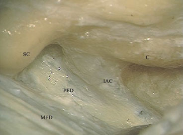
Fig. 5.21 The last shell of bone is to be dissected from the dura using a hook or a dissector. C Cochlea, IAC Internal auditory canal, MFD Middle fossa dura, PFD Posterior fossa dura, SC Superior semicircular canal
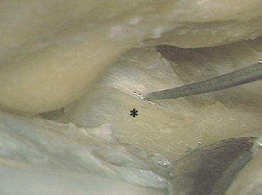
Fig. 5.22 The bony covering of the posterior fossa dura (*) is being removed.
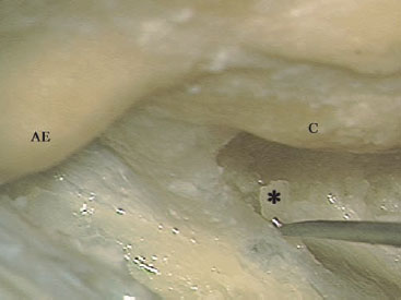
Fig. 5.23 The bony covering of the internal auditory canal and the posterior fossa dura anterior to the canal (*) is being removed. AE Arcuate eminence, C Cochlea
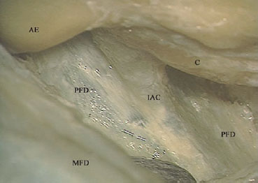
Fig. 5.24 The last bony shell has been removed. AE Arcuate eminence, C Cochlea, IAC Internal auditory canal, MFD Middle fossa dura, PFD Posterior fossa dura
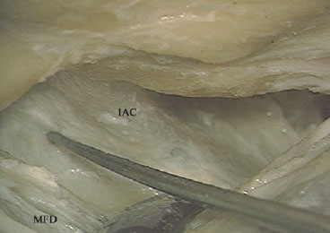
Fig. 5.25 A hook is used to create a hole in the posterior fossa dura. This step is used in live surgery, to reduce intracranial pressure. IAC internal auditory canal, MFD Middle fossa dura
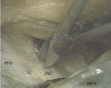
Fig. 5.26 The dura of the internal auditory canal (IAC) is being opened. MFD Middle fossa dura, PFD Posterior fossa dura
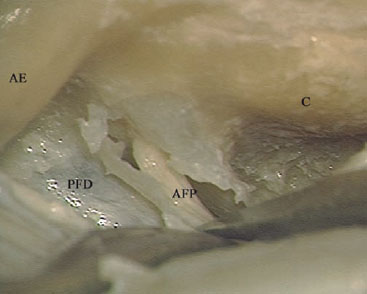
Fig. 5.27 The acousticofacial bundle (AFP) can be seen within the opened internal auditory canal. AE Arcuate eminence, C Cochlea, PFD Posterior fossa dura
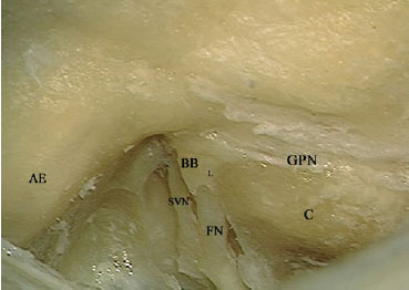
Fig. 5.28 The dura of the internal auditory canal has been further removed. Bill’s bar (BB) can be seen at the level of the fundus. AE Arcuate eminence, C Cochlea, FN Facial nerve within the internal auditory canal, GPN Greater petrosal nerve, L Labyrinthine segment of the facial nerve, SVN Superior vestibular nerve
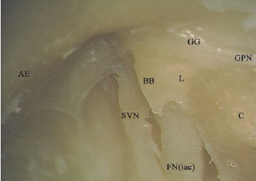
Fig. 5.29 At higher magnification, the relationship at the fundus can be better appreciated. AE Arcuate eminence, BB Bill’s bar, C Cochlea, FN(iac) Internal auditory canal segment of the facial nerve, GG Geniculate ganglion, GPN Greater petrosal nerve, L Labyrinthine segment of the facial nerve, SVN Superior vestibular nerve
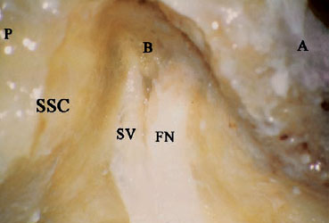
Fig. 5.30 A simple middle cranial fossa approach has been established, and the internal auditory canal dura has been opened. A Anterior, B Bill’s bar, FN Facial nerve, P Posterior, SSC Superior semicircular canal, SV Superior vestibular nerve
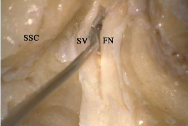
Fig. 5.31 A small hook is used carefully to dislodge the superior vestibular nerve (SV), which is usually free of tumor involvement. FN Facial nerve, SSC Superior semicircular canal
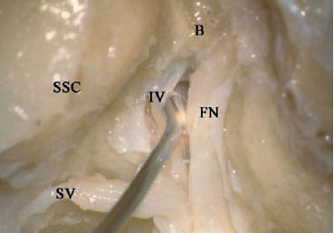
Fig. 5.32 The superior vestibular nerve (SV) has been dissected away, and the hook now is being used to dissect the inferior vestibular nerve (IV). B Bill’s bar, FN Facial nerve, SSC Superior semicircular canal
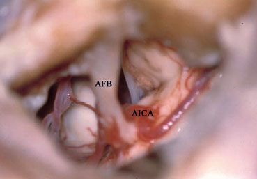
Fig. 5.33 This figure shows the intradural structures that can be seen using a simple middle cranial fossa approach. AFB Acousticofacial bundle, AICA Anterior inferior cerebellar artery
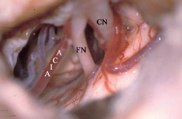
Fig. 5.34 The acousticofacial bundle components have been separated. Both the facial nerve (FN) cochlear nerve (CN) can now be seen. AICA Anterior inferior cerebellar artery
 Middle Cranial Fossa Approach for Tumors of the Labyrinthine Segment of the Facial Nerve (Figs. 5.35–5.47)
Surgical Steps
1. In contrast to vestibular schwannoma surgery, in which it is adequate for exposing the IAC, exposure for FN tumors should be extended distally to encompass the intralabyrin-thine segment, GG, and the beginning of the tympanic segment of the FN. This level of exposure is essential for two reasons: firstly, to obtain adequate control of the extent of the tumor in order to achieve tumor-free margins; and secondly, to allow easy reconstruction of the FN after tumor excision.
2. The first structure to be identified is the GG, if not already dehiscent. To identify it, the greater superficial petrousal nerve is followed posteriorly to where it emerges from the bone. A large diamond drill is used to thin the bone in that area until the GG starts to show through the bone. Once the exact position of the GG has been identified, the drilling area is widened to encompass the whole of the GG, leaving a thin shell of bone overlying it.
3. The FN is now followed proximally toward the intralabyrinthine segment. The beginning of this segment is identified at the most medial part of the GG, where the anterior and posterior margins of the GG join together to form an acute angle. A diamond drill is used to remove the overlying bone. Extreme care should be taken while carrying out this step, since this segment is closely related to the cochlea, which lies anteriorly, and the superior semicircular canal, which lies posteriorly. When the fundus of the IAC is reached, Bill’ bar can be identified separating the FN from the superior vestibular nerve.
4. In live surgery, further exposure of the proximal course of the FN, when indicated by the extent of the pathology, can be achieved using this approach by identifying and uncovering the IAC as described previously.
5. The next step is to identify the beginning of the tympanic segment of the FN. This step is started by drilling the roof of the middle ear, lying posterolateral to the GG. Drilling in this area should be carried out carefully in order not to touch the intact ossicular chain with the rotating burr.
6. Once the ossicular chain has been identified at the level of the incudomalleolar joint, drilling the roof of the middle ear can be safely continued posteriorly to identify the beginning of the horizontal segment of the FN.
Hints and Pitfalls
• This approach is used to resect a facial nerve tumor centered on the labyrinthine segment of the facial nerve. For reconstruction purposes, the facial nerve must be exposed both proximally and distally.
• Sometimes the facial nerve canal is found to be dehiscent due to tumor erosion. If additional drilling is needed, care should be taken not to injure the surrounding vital structures in altered anatomy of this type.
• Since hearing and the ossicular chain are both intact in these cases, extreme care should be taken to avoid touching the ossicular chain with the rotating burr while drilling the roof of the middle ear.
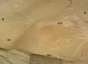
Fig. 5.35 The middle fossa dura of a left temporal bone has been elevated, the greater petrosal nerve (GPN) and the arcuate eminence (AE) identified, and the retractor fixed at the petrous ridge (PR) A Anterior, P Posterior
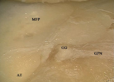
Fig. 5.36 Following the greater petrosal nerve (GPN) and drilling at its roote identifies the geniculate ganglion (GG). AE Arcuate eminence, MFP Middle fossa plate
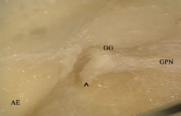
Fig. 5.37 The geniculate ganglion (GG) has been fully exposed, and the beginning of the labyrinthine segment of the facial nerve at the acute angle (^) can be seen. AE Arcuate eminence, GPN Greater petrosal nerve
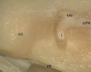
Fig. 5.38 The labyrinthine segment of the facial nerve (L) is followed to the internal auditory canal. AE Arcuate eminence, GG Geniculate ganglion, GPN Greater petrosal nerve, PR Petrous ridge
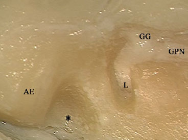
Fig. 5.39 The area (*) between the expected position of the internal auditory canal and the arcuate eminence (AE) is drilled using a large burr. GG Geniculate ganglion, GPN Greater petrosal nerve, L Labyrinthine segment of the facial nerve
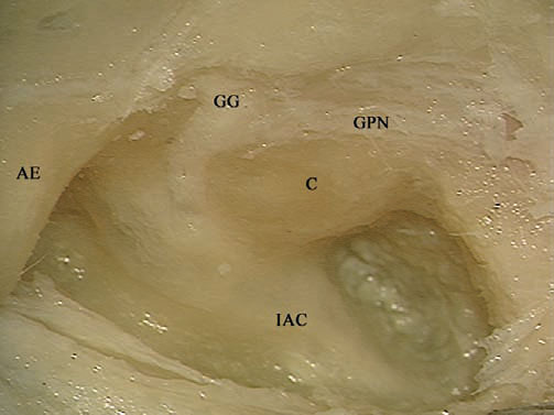
Fig. 5.40 The internal auditory canal (IAC) and cochlea (C) have been identified. AE Arcuate eminence, GG Geniculate ganglion, GPN Greater petrosal nerve
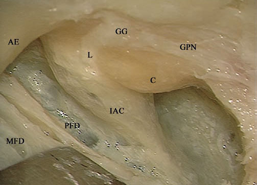
Fig. 5.41 The last shell of bone covering the posterior fossa dura (PFD) and the internal auditory canal (IAC). AE Arcuate eminence, C Cochlea, GG Geniculate ganglion, GPN Greater petrosal nerve, L Labyrinthine segment of the facial nerve, MFD Middle fossa dura
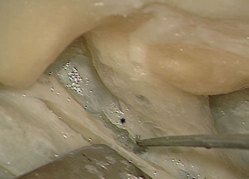
Fig. 5.42 Removal of the last bony shell (*).
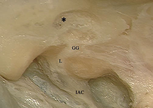
Fig. 5.43 Drilling is now shifted to the middle fossa plate (*), posterolateral to the geniculate ganglion (GG), to identify the head of the malleus and the tympanic segment of the facial nerve. IAC Internal auditory canal, L Labyrinthine segment of the facial nerve
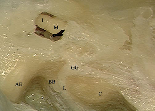
Fig. 5.44 The head of the malleus (M) and body of the incus (I) have been identified in the attic. AE Arcuate eminence, BB Bill’s bar, C Cochlea, GG Geniculate ganglion, L Labyrinthine segment of the facial nerve
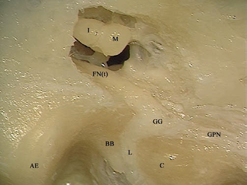
Fig. 5.45 After adequate drilling of the middle fossa plate (the roof of the middle ear), the tympanic segment of the facial nerve (FNt) has been identified. AE Arcuate eminence, BB Bill’s bar, C Cochlea, GG Geniculate ganglion, GPN Greater petrosal nerve, I Body of the incus, L Labyrinthine segment of the facial nerve, M Head of the malleus
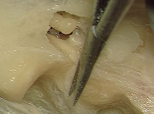
Fig. 5.46 The dura of the internal auditory canal is being opened
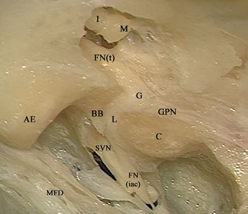
Fig. 5.47 The view after completion of the approach. AE Arcuate eminence, BB Bill’s bar, C Cochlea, FN(iac) Internal auditory canal segment of the facial nerve, FN(t) Tympanic segment of the facial nerve, G Geniculate ganglion, GPN Greater petrosal nerve, I Body of the incus, L Labyrinthine segment of the facial nerve, M Head of the malleus, MFD Middle fossa dura, SVN Superior vestibular nerve
 Combined Middle Cranial Fossa Transpetrous Approach (Figs. 5.48–5.64)
Indications
• Small petroclival tumors anterior to the internal auditory canal, when hearing preservation is planned.
• Small and moderate-sized tumors of the superior cerebellopontine angle, when hearing preservation is planned.
Surgical Steps
1. The craniotomy used for this approach is wider anteroposteriorly than that used for the simple middle cranial fossa approach, to provide adequate control of the petrous apex.
2. Dural elevation proceeds in the same manner as in the simple middle cranial fossa approach. The only difference is that the middle meningeal artery is coagulated and transected to provide adequate control over the petrous apex.
3. Identification of the internal auditory canal is achieved as previously described.
4. After the internal auditory canal has been completely skeletonized, the mandibular division of the trigeminal nerve is identified. To allow the drilling of the petrous apex to proceed anteriorly, the mandibular nerve should either be retracted anteriorly or transected, depending on the availability of space.
5. Drilling now proceeds carefully to identify and skeletonize the horizontal segment of the internal carotid artery. If the cavernous sinus is to be reached, then the mandibular nerve has to be sacrificed to obtain the required access.
6. Drilling should include the whole petrous apex, reaching to the clivus area.
Hints and Pitfalls
• Although this approach provides additional exposure of the petroclival area, the working area is narrow in comparison with the transcochlear approach, and the use of this approach should therefore be limited to selected cases.
• To achieve the additional anterior exposure, the middle meningeal artery and sometimes the mandibular division of the trigeminal nerve have to be sacrificed.
• Extreme care must be taken when drilling in the region of the internal carotid artery. Only diamond burrs moved parallel to the artery should be used.
• Bleeding encountered from the inferior petrosal sinus and from the clivus bone can be stopped using a diamond burr.
• The dura of the clivus is opened only after adequate drilling of the clivus bone. Care should be taken while opening the dura not to injure the abducent nerve as it passes through Dorello’s canal.
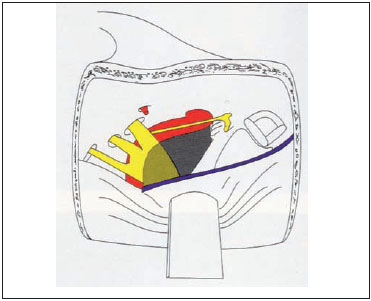
Fig. 5.48 An illustration of a right middle cranial fossa. The gray color represents the amount of petrous apex bone removal required to achieve a middle cranial fossa transpetrous approach.
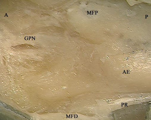
Fig. 5.49 The middle fossa dura (MFD) of a right temporal bone has been elevated from the middle fossa plate (MFP). Since wider exposure is needed in this case, the middle meningeal artery has been transected. A Anterior, AE Arcuate eminence, GPN Greater petrosal nerve, P Posterior, PR Petrous ridge
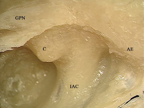
Fig. 5.50 The internal auditory canal (IAC) and cochlea (C) have been identified. Note that bone removal anterior to the canal is wider than in the simple middle fossa approach. AE Arcuate eminence, GPN Greater petrosal nerve
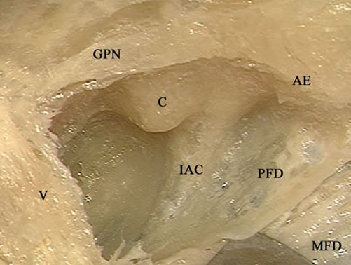
Fig. 5.51 The last shell of bone covering the dura is to be dissected using a hook or a dissector. V Trigeminal nerve, AE Arcuate eminence, C Cochlea, GPN Greater petrosal nerve, IAC Internal auditory canal, MFD Middle fossa dura, PFD Posterior fossa dura
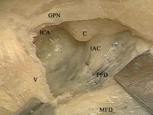
Fig. 5.52 The last bony shell has been removed. V Trigeminal nerve, C Cochlea, GPN Greater petrosal nerve, IAC Internal auditory canal, ICA Internal carotid artery, MFD Middle fossa dura, PFD Posterior fossa dura
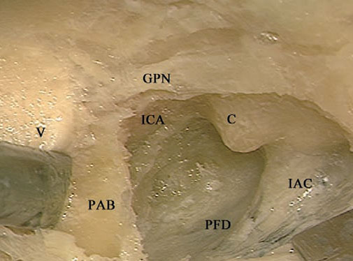
Fig. 5.53 The trigeminal nerve (V) is retracted in order to drill the petrous apex bone (PAB) lying underneath it. C Cochlea, GPN Greater petrosal nerve, IAC Internal auditory canal, ICA Internal carotid artery, PFD Posterior fossa dura
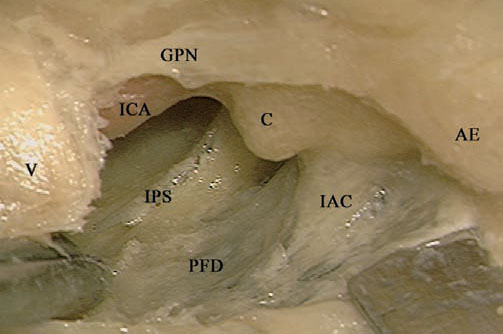
Fig. 5.54 The bone underneath the petrous apex has been drilled, the inferior petrosal sinus (IPS) has been identified, and the internal carotid artery (ICA) is better skeletonized. Note that the extent of bone removal at the petrous apex level is not yet sufficient to expose all of the horizontal segment of the internal carotid artery. V Trigeminal nerve, AE Arcuate eminence, C Cochlea, GPN Greater petrosal nerve, IAC Internal auditory canal, PFD Posterior fossa dura
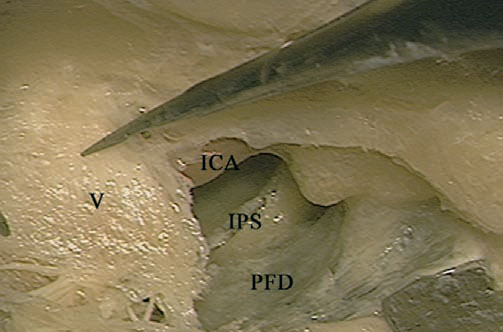
Fig. 5.55 To obtain access to the horizontal segment of the internal carotid artery (ICA), the mandibular branch of the trigeminal nerve (V) is being cut. IPS Inferior petrosal sinus, PFD Posterior fossa dura
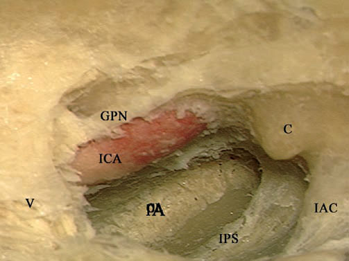
Fig. 5.56 The horizontal segment of the internal carotid artery (ICA) is better skeletonized, and the drilling is extended to the petrous apex (PA). C Cochlea, GPN Greater petrosal nerve, IAC Internal auditory canal, IPS Inferior petrosal sinus, V Trigeminal nerve
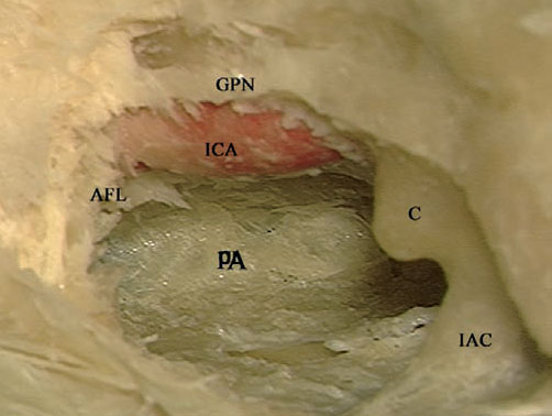
Fig. 5.57 The horizontal segment of the internal carotid artery (ICA) has been skeletonized up to the anterior foramen lacerum (AFL) and the petrous apex (PA) has been fully drilled. C Cochlea GPN Greater petrosal nerve, IAC Internal auditory canal
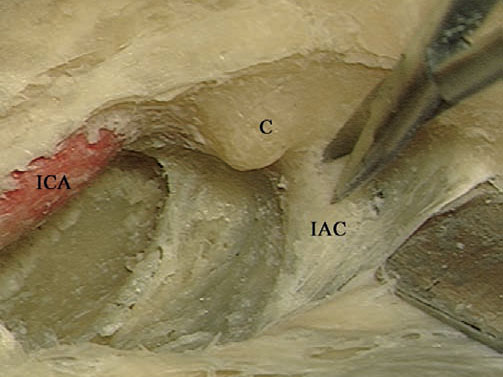
Fig. 5.58 The dura of the internal auditory canal (IAC) is being opened. C Cochlea, ICA Internal carotid artery
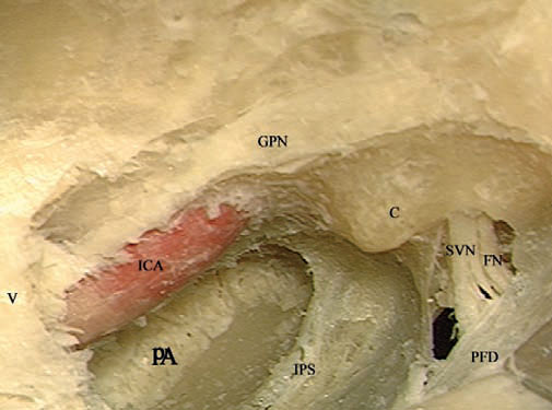
Fig. 5.59 The view after the completion of the approach. V Trigeminal nerve, C Cochlea, FN Facial nerve, GPN Greater petrosal nerve, ICA Internal carotid artery, IPS Inferior petrosal sinus, PA Petrous apex, PFD Posterior fossa dura, SVN Superior vestibular nerve
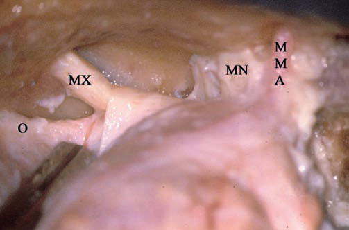
Fig. 5.60 To provide a clearer picture of the approach, the last part of the approach is shown here in a right-sided cadaveric dissection. Seen here are the middle meningeal artery (MMA) and the mandibular (MN), maxillary (MX), and ophthalmic (O) divisions of the trigeminal nerve as they enter their foramina.
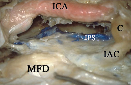
Fig. 5.61 The required bone drilling as described above has been carried out. C Cochlea, IAC Internal auditory canal, ICA Internal carotid artery, IPS Inferior petrosal sinus, MFD Middle fossa dura
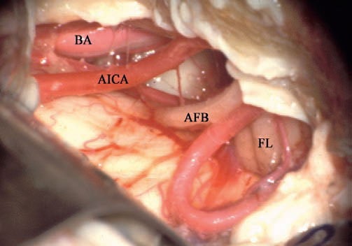
Fig. 5.62 The dura has been opened, and the cerebellopontine angle can be seen. AFB Acousticofacial bundle, AICA Anterior inferior cerebellar artery, BA Basilar artery, FL Flocculus
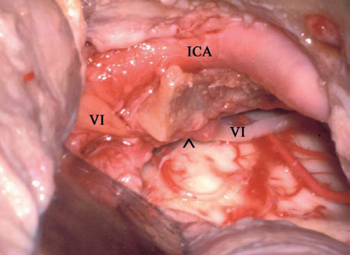
Fig. 5.63 Examining the anterior part of the approach, the abducent nerve (VI) can be seen entering Dorello’s canal (^), and the internal carotid artery (ICA) can be seen entering the anterior foramen lacerum, passing to the cavernous sinus.
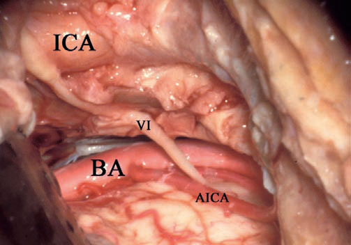
Fig. 5.64 The last piece of bone has been drilled away, and the approach is completed. Seen here is the prepontine cistern, which is the main target for which this approach is performed. VI Abducent nerve, AICA Anterior inferior cerebellar artery, BA Basilar artery, ICA Internal carotid artery
 Combined Transmastoid Middle Cranial Fossa Approach (Figs. 5.65–5.78)
Indications
The aim of this approach is to achieve adequate exposure of the full length of the intratemporal facial nerve without compromising preoperatively preserved hearing.
• Facial nerve tumors centered on the geniculate ganglion and extending both proximally and distally.
• Exploration of the facial nerve after a temporal bone fracture.
Surgical Steps
1. The mastoid cavity is prepared in the same manner as in the closed tympanoplasty approach. The only difference here is that extra care is taken to maintain the integrity of the middle fossa dural plate. For this reason, the plate is not thinned too much here
2. The same craniotomy as that used in the middle cranial fossa (MCF) is carried out here. In this approach, evaluating the lower limit is easier than in the regular MCF approach, as the level of the middle cranial fossa plate can be actively visualized after the mastoidectomy. It is important to ensure that the lateral edge of the middle fossa plate contains no ridges or bony overhangs from either side, to allow simultaneous visualization of structures on both sides of the plate.
3. Once the dura has been elevated and the middle fossa retractor applied, a connection between the two approaches is established by drilling a small hole at the middle fossa plate at the level of the head of the malleus. This connection, in addition to facilitating surgical manipulation of the perigeniculate portion of the FN, also provides a valuable guide to the position of the GG, since it can be seen in the attic.
4. The subsequent steps are the same as those described in the MCF approach for facial nerve tumors.
Hints and Pitfalls
• The middle fossa plate will form the barrier between the intracranial cavity and the mastoid cavity created in this approach. The utmost care should be taken to preserve its integrity, to avoid CSF leakage and meningoencephalic herniation.
• If difficulties are encountered in identifying the geniculate ganglion, the level of the head of the malleus as seen from the atticotomy can be a useful guide for the location of the ganglion.
• At the end of the procedure, cartilage and fibrin glue are used to reconstruct the defect created in the middle fossa plate.
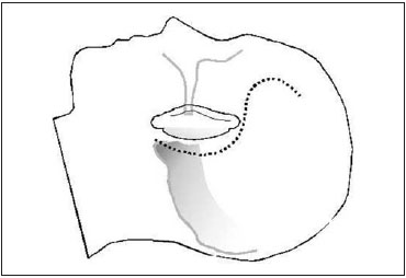
Fig. 5.65 An S-shaped incision is made as shown.
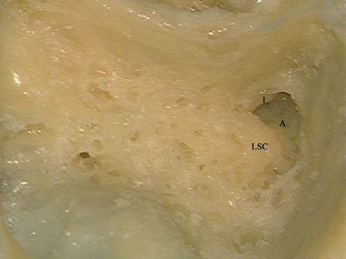
Fig. 5.66 The lateral semicircular canal (LSC) and the short process of the incus (I) have been identified within the mastoid antrum (A) of a left temporal bone.
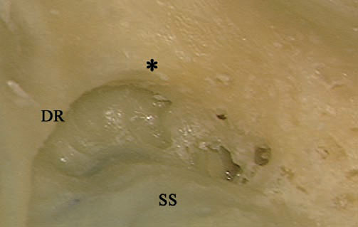
Fig. 5.67 The digastric ridge (DR) can be seen, pointing toward the facial nerve at the level of the stylomastoid foramen (*). SS Sigmoid sinus
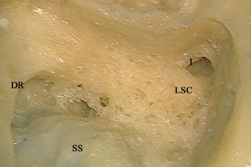
Fig. 5.68. The mastoid segment of the facial nerve, extending from between the lateral semicircular canal (LSC) and short process of the incus (I) to the anterior edge of the digastric ridge (DR), is to be skeletonized. SS Sigmoid sinus
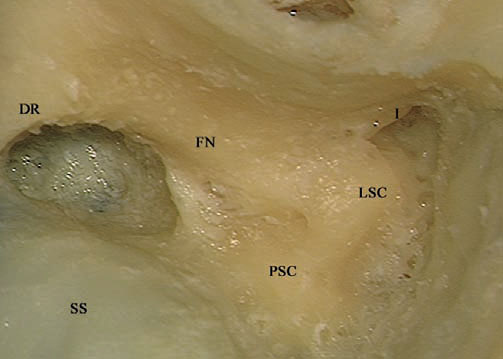
Fig. 5.69 The mastoid segment of the facial nerve (FN) has been identified. DR Digastric ridge, I Short process of the incus, LSC Lateral semicircular canal, PSC Posterior semicircular canal, SS Sigmoid sinus
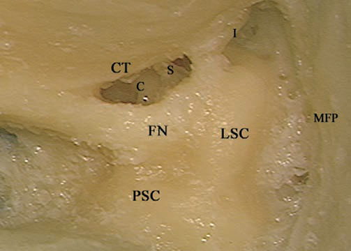
Fig. 5.70 A posterior tympanotomy has been carried out. C Cochlea, CT Chorda tympani, FN Facial nerve, I Short process of the incus, LSC Lateral semicircular canal, MFP Middle fossa plate, PSC Posterior semicircular canal, S Stapes
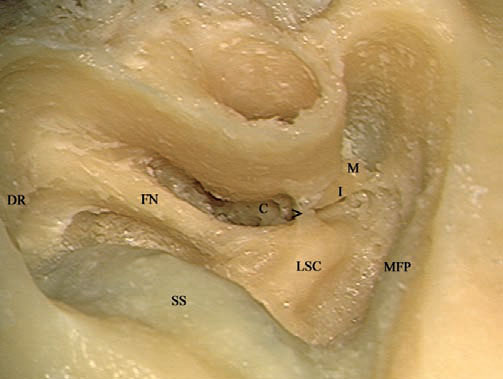
Fig. 5.71 The posterior tympanotomy has been extended toward the hypotympanum and an atticotomy has been carried out. The last strut of bone (>) left to protect the incus from the drill should be removed using a curette. C Cochlea, DR Digastric ridge, FN Facial nerve, I Incus, LSC Lateral semicircular canal, M Malleus, MFP Middle fossa plate, SS Sigmoid sinus
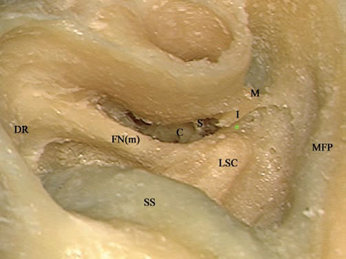
Fig. 5.72 After the removal of the last strut of bone, the tympanic segment of the facial nerve (*) can be seen. C Cochlea, DR Digastric ridge, FN(m) Mastoid segment of the facial nerve, I Incus, LSC Lateral semicircular canal, M Malleus, MFP Middle fossa plate, S Stapes, SS Sigmoid sinus
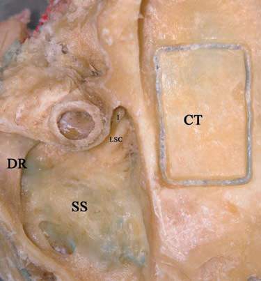
Fig. 5.73 Attention is nowshifted to the middle cranial fossa component of the approach. The craniotomy (CT) is created. Note that the middle fossa plate is less beveled than in a regular closed tympanoplasty. DR Digastric ridge, I Incus, LSC Lateral semicircular canal, SS Sigmoid sinus
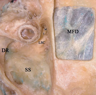
Fig. 5.74 The craniotomy bone has been separated from the middle fossa dura (MFD). DR Digastric ridge, I Incus, LSC Lateral semicircular canal, M Malleus, SS Sigmoid sinus
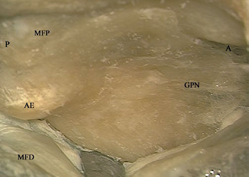
Fig. 5.75 The middle fossa dura (MFD) has been elevated, and the greater petrosal nerve (GPN) and the arcuate eminence (AE) have been identified. A Anterior, MFP Middle fossa plate, P Posterior
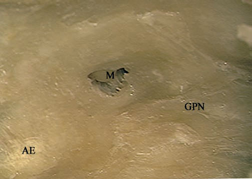
Fig. 5.76 The middle fossa plate has been drilled over the location of the malleus head (M), as judged from the middle ear. AE Arcuate eminence, GPN Greater petrosal nerve
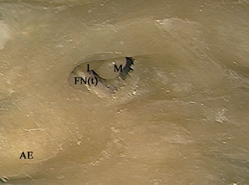
Fig. 5.77 Further removal of the middle fossa plate exposes the tympanic segment of the facial nerve (FNt). AE Arcuate eminence, I Incus, M Malleus
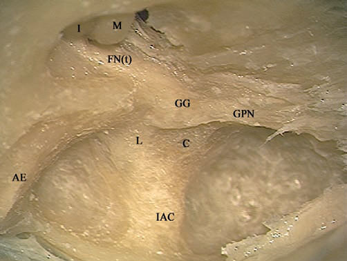
Fig. 5.78 The full course of the facial nerve has now been identified. Further steps depend on the extent of the pathology being treated. AE Arcuate eminence, C Cochlea, FN(t) Tympanic segment of the facial nerve,GG Geniculate ganglion, GPN Greater petrosal nerve, I Incus, IAC Internal auditory canal, L Labyrinthine segment of the facial nerve, M Malleus
< div class='tao-gold-member'>


