The Optics of Wavefront Technology
Jim Schwiegerling
Wavefront technology has undergone an explosive development in recent years and continues to be one of the most rapidly developing technologies in ophthalmic research. The primary driving force behind this rapid development is the refractive surgery industry, which is pushing toward the goal of improved visual performance following surgery. There are at least six commercially available systems for measuring wavefront errors in the eye, with alternative technologies emerging as early research prototypes. These systems are based on a variety of techniques for measuring wavefronts. The objective of these devices is to enable the ophthalmic practitioner to provide improved correction of the refractive state of the eye and possibly improved diagnoses through superior retinal imaging.
Most imaging systems, including the eye, are designed to take points of light out in the world and relay them to a perfect focus on an image plane. To accomplish this task, the imaging system must convert the shape of wavefronts. Figure 1 illustrates a typical imaging system. A point of light gives off a series of expanding spherical wavefronts. These wavefronts propagate outward and are intercepted by the lens. The lens is designed to convert the expanding wavefronts into converging wavefronts that focus to a point. If the point of light is far from the lens, the wavefronts impinging on the lens have expanded to such a degree that they are perfectly flat plane waves. In terms of the eye, the ideal performance is that plane waves from a distant point are converted to perfectly spherical waves that converge to a point on the retina. For points closer to the eye, ideally the eye accommodates to convert the diverging wavefronts from the near object into perfectly spherical wavefronts that focus to a point on the retina.
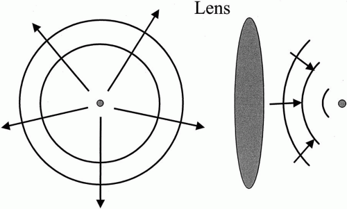 Fig. 1. Expanding wavefronts from a point of light are captured by an imaging system and converted to converging spherical wavefronts. These converging wavefronts focus to a point. |
All optical systems, including the eye, suffer from aberrations. Aberrations are errors introduced by the optical system that cause the perfectly spherical converging wavefronts to distort from their ideal shape, ultimately causing an imperfect focus. Eye care providers are familiar with some of the basic aberrations, but may be less familiar with the more complex aberrations. Basic aberrations (or low-order aberrations) include spherical refractive error, also known as defocus in the wavefront world, and astigmatism. These aberrations of the eye cause the wavefronts within the eye to deviate from their ideal shape. In the case of myopia, the converging wavefronts focus too quickly, converging to a point in front of the retina. In the case of hyperopia, the wavefronts do not converge rapidly enough, and the focus ends up behind the retina. In the case of astigmatism, the focus of the wavefront depends on meridian. There are two reasons these aberrations are familiar to practitioners. First, refractive error and astigmatism cause the bulk of the degradation in visual performance in the general population. Second, there are practical means for which to correct these errors (i.e., spectacles and contact lenses). However, more complex aberration types exist in the eye. These types are known as higher-order aberrations. The higher-order aberrations are what limit visual acuity to about 20/20 even with the correction of spherical and cylindrical refractive error.
The goal of wavefront technology is to measure the aberrations of the eye. By measuring the aberrations of an individual eye, a custom correction based on the individual’s aberration structure can be defined. Whereas many of the techniques for measuring wavefront aberrations have existed for a long time, the recent explosion in wavefront technology has occurred because the means for correcting these aberrations on an individual basis now exist in the form of scanning refractive surgery lasers and optometric lathes that can cut nonrotationally symmetric surfaces. These new custom corrections promise to improve visual performance better than conventional modes of correction.
Measurement of wavefront aberrations is called wavefront sensing or aberrometry. This chapter outlines the different classes of aberrometers and reviews four commercially available techniques for performing wavefront sensing: the Shack-Hartmann technique, the Tscherning technique, retinal raytracing, and the spatially resolved refractometer. The advantages and disadvantages of the techniques are compared. Finally, applications of the wavefront sensors are described.
OUTGOING VERSUS INGOING ABERROMETRY
Aberrometers fall into two main classes: outgoing and ingoing. Outgoing aberrometers operate by placing a point source of light on the retina and determining the shape of the wavefront emerging from the eye (Fig. 2). A point source of light on the retina emits diverging spherical wavefronts that pass through the crystalline lens and the cornea to exit the eye. A perfect eye would not introduce any aberrations into the wavefront, and perfectly planar wavefronts would emerge from the eye. However, if the optics of the eye introduce aberrations, the emerging wavefronts deviate from the ideal planar shape. Outgoing aberrometers operate on the principal of the reversibility of light. If a point source on the retina results in plane waves emanating from the eye, then plane waves incident on the eye will focus to a perfect point on the retina. Outgoing aberrometers typically measure the slope or direction of travel of the wavefront (Fig. 3). The arrows in Figure 3 show the local direction of travel of the aberrated wavefront. Outgoing aberrometers measure the directions of these arrows at a series of points across the pupil of the eye and use this information to reconstruct the shape of the wavefront.
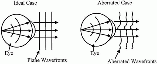 Fig. 2. A point source of light emits diverging spherical wavefronts that exit the eye. A perfect eye would have planar wavefronts emerging from it. Aberrations in the eye cause the emerging wavefront to deviate from this planer shape. |
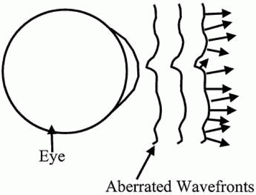 Fig. 3. Outgoing aberrometers measure the slope or direction of travel of the wavefront at a series of points across the pupil. |
Ingoing aberrometers operate by examining how wavefronts external to the eye are altered as they pass through the optics of the eye (Fig. 4). In the case where no aberrations are present, plane wavefronts incident on the eye are converted to perfectly spherical wavefronts and converge to a point on the retina. When aberrations are introduced by the optics of the eye, the converging wavefronts are no longer spherical and a blurry spot is formed on the retina. As shown in Figure 5, ingoing aberrometers typically measure the transverse ray error. In other words, in the ideal case, a ray of light entering the eye focuses to the fovea. When aberrations are present, the ray strikes the retina at a point away from the fovea. Ingoing aberrometers measure the distance between the fovea and the point where the ray strikes the retina. This distance is proportional to the slope of the wavefront and can ultimately be used to reconstruct the shape of the wavefront.
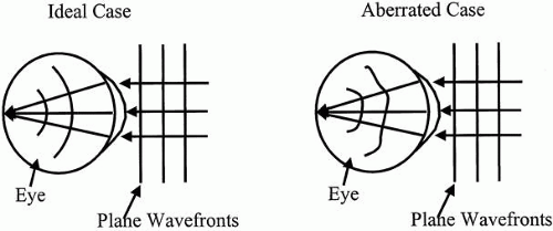 Fig. 4. Plane wavefronts incident on the eye are convened to perfectly spherical wavefronts and converge to a point on the retina in the aberration-free case. In the presence of aberrations, the converging wavefronts are no longer spherical and a blurry spot is formed on the retina. |
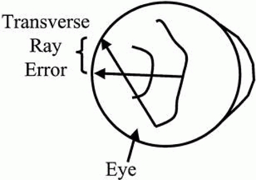 Fig. 5. A ray of light in an aberrated eye will strike the retina at a point away from the fovea. The transverse ray error is the distance between where the ray strikes the retina and the fovea. |
TECHNIQUES FOR ABERRATION MEASUREMENT IN THE EYE
A variety of techniques can be used to measure the aberrations of the eye. Four methods have found their way into commercial products and are discussed in detail. The origins of the techniques are fairly old, but the development of new surgical and manufacturing techniques has brought the methods into modern and automated systems that can rapidly and accurately measure the aberrations of the eye.
SHACK-HARTMANN TECHNIQUE
The Shack-Hartmann technique is an evolution of the Hartmann screen test. Platt and Shack give an excellent review of the history behind this technique and its application to the eye.1 The Hartmann screen test was employed in the early 1900s to test the quality of large astronomic telescope mirrors.2,3 In this test, a wooden board with a series of holes is placed over the surface of a telescope mirror (Fig. 6). The wooden board acts as a mask that takes light from a distant point, creating individual pencils of light on reflection from the mirror. These pencils converge toward the mirror focus. Photographic plates are inserted on either side of the focus to record the pattern of spots created by the pencils. Knowing the separation between the photographic plates and the positions of the spots on the plate allows for rays to be drawn between the two plates. High-quality mirrors have rays that all cross at the same point, whereas poor-quality mirrors have rays that cross the axis of the mirror at all different points, as shown in Figure 6. In the late 1960s, Shack and his colleagues developed the modern day version of the Shack-Hartmann sensor.4 The original application of the technology was to measure the aberrations caused by atmospheric turbulence to improve the quality of observation from ground-based telescopes. In the modern-day system, Shack replaced the mask with an array of tiny lenses to improve light-gathering capacity and to record wavefront slope directly. In the early 1990s, Liang and colleagues5 applied the Shack-Hartmann technique to the eye, and it is this configuration that makes up most of the commercially available systems (Fig 7). The Shack-Hartmann system is an example of outgoing aberrometry. A narrow beam of light is directed into the eye and forms a small point of light on the retina. This light scatters off the retina and emanates out of the eye. A lenslet array intercepts the emerging wavefront. In the aberration-free case, shown on the left in Figure 7, plane wavefronts emerge from the eye. Each tiny lenslet intercepts a portion of the wavefront that is flat and is traveling in the direction of the axis of the lenslet. The lenslet focuses the light down to a point, and the result is a grid of uniformly spaced spots at the back focal points of the lenslets. In the aberrated case, shown on the right in Figure 7, the emerging wavefront is no longer planar, but instead takes on a complex shape. Each individual lenslet in this case intercepts a small portion of the aberrated wavefront that is approximately planar over the aperture of the lenslet. However, the wavefront can be tilted with respect to the lenslet axis. The light will still focus to the rear focal plane of the lenslet, but the spot location will be shifted because of the wavefront tilt. The resulting spot pattern for an aberrated wavefront is a distorted grid of spots. By comparing the deviation in spot locations between the aberrated and the ideal wavefronts, the wavefront slope and ultimately the wavefront shape can be recovered.
Stay updated, free articles. Join our Telegram channel

Full access? Get Clinical Tree


