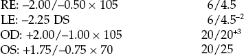
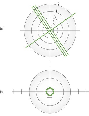
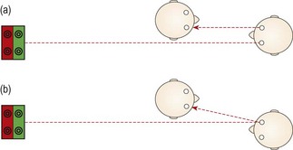
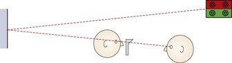
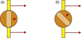
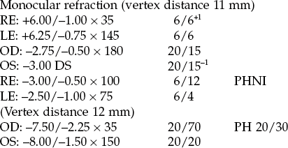
4 4.1 Differential diagnosis information from other assessments 4.3 Interpupillary distance (PD) 4.6 Monocular subjective refraction 4.7 Best vision sphere (maximum plus to maximum VA; MPMVA) 4.8 Best vision sphere (the plus/minus technique) 4.9 Duochrome (or bichromatic) test 4.10 Assessment of astigmatism 4.12 Binocular subjective refraction The natural progression of the type of ametropia given the patient’s age can indicate what change in refractive correction to suspect. For example, a childhood-onset myope who obtained their first spectacles at age 12 and is now 16 is likely to attend an examination complaining of increased myopia given the typical progression of myopia. Any mention of cataracts in the case history should lead to a careful investigation for increased myopia (nuclear cataract) or astigmatic change (cortical cataract).1 When examining children who do not wear spectacles, it is useful to ask whether any of the patient’s family wear glasses or contact lenses. Mutti and colleagues reported that juvenile onset myopia was evident in 33% of the offspring of two myopic parents, compared with only 6% of the children of two non-myopic parents.2 A family history of hyperopia highlights possible amblyopia. Diabetes, either undiagnosed or poorly controlled, can lead to wide fluctuations in refractive error, with either hyperopic or myopic shifts. In addition, a variety of systemic medications can lead to refractive error shifts.3 For low myopic refractive errors and hyperopic changes in absolute presbyopes, a degradation of one line of vision (on a logMAR chart) corresponds to approximately −0.25 D of refractive error (although very approximate and dependent on pupil size and patient blur tolerance).4 For example: 1. Vision of 20/40 (6/12) in a young adult patient suggests a four-line loss in VA and an equivalent spherical correction of approximately −1.00 DS. 2. Astigmatism in adults changes with age from with-the-rule in young adults to against-the-rule in older patients.5 However, these changes in astigmatism are often minimal over the typical 1–3 year period between eye examinations, so that habitual distance VA reductions in spectacle wearing myopic astigmats and older hyperopic astigmats tend to indicate the change in spherical power required. Therefore, a myope of −1.00/−0.50 × 180 with a habitual VA of 6/12 or 20/40 is likely to need a change in refractive correction of -1.00 DS and an updated prescription to approximately −2.00/−0.50 × 180. These devices are also referred to by trade names in some countries, including lensometer or lensmeter (America) and vertometer (Australia). Automatic focimeters are available that measure the lens characteristics mentioned above once the lens has been appropriately positioned and provide a printout of the results. These are very simple to use and the measurement procedure will not be explained. Their main disadvantage is that they break down more often than non-automated focimeters.6 1. Explain the test to the patient: ‘I am going to measure the power of your spectacles.’ 2. Set the power of the focimeter to zero and focus the eyepiece (turn it as far anti-clockwise as possible, then slowly turn it clockwise until the target and graticule first come into sharp focus). 3. Measure the back vertex power (BVP) by placing the spectacles on the focimeter with the back (ocular) surface away from you. Position the middle of the right lens against the lens stop. 4. Look into the focimeter and adjust the lens position vertically (using the lens table) and horizontally until the illuminated target is placed in the middle of the reticule. If the lens is high powered, you may need to turn the power wheel to bring the target into focus before it can be centred. 5. Fix the lens into position using the lens retainer. 6. To obtain the power of the sphere, turn the power wheel to bring the target into focus. (a) If the entire target is focused at the same time (Figure 4.1), the lens is a sphere and there is no cylindrical component. Record the sphere power for the right eye from the power wheel or the internal scale and go to step 8. Fig. 4.1 The entire focimeter target is in focus at the same time, indicating a spherical lens. The graticule scale allows measurement of prism. (a) A focimeter that uses a cylindrical (3-line) and spherical (1-line) target. The graticule scale is numbered 1 to 5. (b) A focimeter that uses a circle of dots target. The graticule scale is indicated by the intersecting lines and runs from 1–5 horizontally and 1–3 vertically in both directions from the centre. With an astigmatic lens, the dots become lines orientated along the two principal meridians. (b) If parts of the target are in focus at different powers and to record in the standard negative cylinder format, turn the power wheel until the meridian with the most plus power (or least minus power) is brought into focus. (c) With focimeters using line targets, rotate the axis wheel until the sphere line (Figure 4.1a) is in focus and the line is continuous without breaks. You may need to use the power wheel to gain best focus. (d) Record the sphere power from the power wheel or internal scale. 7. To obtain the power and axis of the cylinder: (a) Focus the image in the meridian at 90° from the first meridian by turning the power wheel towards the most minus (or least plus) power. (b) Read off the power when this meridian is in focus. With focimeters using line targets, the cylinder lines will be in focus. (c) Record the difference between the sphere power from step 6d and the new meridian power as the cylinder power. (d) Record the orientation of the second meridian from the eyepiece protractor or the axis wheel as the cylinder axis. With focimeters using line targets, this will be the orientation of the cylinder lines (Figure 4.1a). 8. Make sure the target is centred in the graticule and dot the right lens using the focimeter’s marking device. This could be just one spot (the lens optical centre) or three dots (the middle is the lens optical centre, the other two indicate the horizontal line). 9. Release the lens retainer and repeat steps 5 to 8 for the left eye. Do not change the vertical position of the lenses between measurements of the right and left lenses as you need to determine if any vertical prism is incorporated in the spectacles. 10. Move the lens horizontally until the target is in the same vertical plane as the centre of the graticule and dot the left lens using the focimeter’s marking device. 11. If the target is above or below the centre of the graticule, vertical prism is present and should be recorded to the nearest 0.5Δ using the graticule scale (Figure 4.1). 12. Remove the spectacles from the focimeter and measure the distance between the right and left optical centres to calculate the distance between centres (DBC). Record the DBC in mm. 13. For front-surface solid multifocal lenses, the reading add must be measured using front vertex power (FVP). Turn the lens around so that the ocular surface faces you and reposition the spectacles in the focimeter. Measure the FVP along one meridian in the distance portion of the spectacles. Measure the FVP along the same meridian in the near portion of the spectacles. The difference between these powers is the reading addition. Repeat the measurement in the left lens. For low-powered lenses, the FVP approximately equals the BVP, and the BVP add can be measured. 14. For progressive addition lenses (PALs), the appropriate position on each lens to measure the distance and near prescription, optical centres and any prism must first be found (Figure 4.2). A faint mark is etched into both the nasal and temporal sides of each lens, and this must be found and marked with a non-permanent marker. The mark may also indicate the PAL manufacturer and the power of the addition. Use the manufacturer’s marking up card, to find the appropriate distance and near centres and measure the sphero-cylindrical power as previously described. Use the card to determine where to mark the optical centres and where to check for any prism (Figure 4.2). 15. Compare the distance DBC and the patient’s interpupillary distance (PD). If these distances are different, calculate the induced horizontal prism using Prentice’s rule (induced prism = Fc, where F is the power of the lens along the horizontal meridian and c is the difference between the DBC and PD in cm). The direction of the prism also needs to be deduced. One of the most common errors in focimetry is an axis reading incorrect by 90°.6 Given that the cylindrical axes in the two eyes are often mirror images of each other (for example, both axes 90° or both axes 180°; right axis 175°, left 5°; right 20°, left 160°; right 45°, left 135° etc.), if axes are 90° different to this (for example, 180° and 90°; 175° and 95°; 20° and 50°; both axes 45°; both axes 135°) then recheck the two cylindrical axes.5,7 Reading additions are typically the same in both eyes, so that if they are read as different, they should be rechecked. (a) Reading one or both of the cylindrical axes incorrectly by 90°.6 (b) Not focusing the focimeter eyepiece. This can lead to inaccuracies for high-powered lenses. (c) Not measuring the reading addition using FVP measurements for front-surface solid multifocals. (d) Ignoring the relative vertical position of the target between the right and left lens, thereby missing vertical prism. (e) Changing the vertical position of the lenses between measurements of the right and left lenses, thereby incorrectly reading vertical prism. (a) To place the optical centre of the phoropter/trial frame lenses in front of the patient’s visual axes to control prism and avoid aberrations. (b) So that the optical centre of spectacle lenses can be placed in front of the patient’s visual axis to avoid unwanted prism and aberrations or deliberately placed elsewhere to produce desired prism. Anatomical PD measurement is quick and convenient to use during an eye examination and it requires no instrumentation other than a simple millimetre ruler. The repeatability of anatomical binocular PD measurements is similar to that for a pupillometer.8,9 A pupillometer could be considered when refracting or dispensing a patient with a large amount of ametropia, where slight discrepancies in PD could lead to induced prism, and for monocular measurements when dispensing progressive addition lenses. 2. Explain the test to the patient: ‘I am going to measure the distance between your eyes so that I can put your lenses in the correct position for your eyes.’ 3. Face the patient directly at the distance desired for the near PD (usually about 40 cm). 4. Rest the PD ruler on the bridge of the patient’s nose or on the forehead so that the millimetre scale is within the spectacle plane. Steady your hand with your fingers on the patient’s temple to ensure that the ruler is held firmly in place. 5. Close your right eye and ask the patient to look at your left eye. (It is usually easiest to indicate with your finger the eye that you want the patient to fixate.) To allow a patient with unilateral strabismus to fixate, you may need to cover the fellow eye. 6. Choose a point of reference on the patient’s right eye. The temporal pupil margin is usually most convenient, although the centre of the pupil or the temporal limbus margin may also be used and the latter may be essential with patients with dark irides. Align the zero point on the ruler with this reference point. 7. Close your left eye, open your right and ask the patient to change fixation to your open right eye. Take care not to move the ruler or your head position. By sighting again to the appropriate reference point on the patient’s left eye, you will obtain a reading for the distance PD (Figure 4.3). This would be the left nasal pupil margin if you used the temporal pupil margin of the right eye. 8. Move laterally to place your dominant eye opposite the patient’s nose. 9. Ensure that you are still at a distance from the patient equal to their near working distance. Normally this is done at 40 cm but, if desired, the near PD can be measured for a closer or farther working distance. 10. Using your dominant eye only, choose a point of reference on the patient’s right eye and align the zero point on the ruler with this reference point. 11. Look over to the patient’s left eye and note the reading on the ruler that aligns with the corresponding reference point on the left eye (Figure 4.3a). The values are normally recorded as distance PD/near PD (in mm). For example, PD: 63/60. For women the distance PD is most commonly in the range of 55 to 65 mm, and for men, 60 to 70 mm.10 Young children may have PDs as low as 45 mm. The distance PD value is usually 3 or 4 mm greater than the near PD at 40 cm.10 Inaccuracies in anatomical PD can occur due to parallax error when there is a large difference between your PD and patient’s PD. However, the error is slight, with an 8 mm difference in the examiner and patient’s PDs leading to a 0.5 mm error in the measured patient PD.11 The repeatability of anatomical PDs taken by an experienced practitioner is approximately ± 1–2 mm.8,9 Repeatability between practitioners is slightly poorer at about ±1.5–2 mm.9 1. Moving the ruler during the measurement. Make sure it is held firmly and steadily in position. After taking the distance PD reading, it is a good idea to re-open your left eye, have the patient switch fixation back to it and check that the zero mark on the ruler is still aligned with the original reference point on the patient’s right eye. 2. Using an inaccurate near test distance. Most commonly, unwittingly drifting in closer than 40 cm so the near PD turns out to be lower than it should be. The test distance should not affect the distance PD measurement. 3. Using a PD ruler that is not accurately calibrated, such as some give-away rulers provided by optical companies. Pupillometers allow monocular PDs to be measured more accurately than an anatomical measurement.9 This is beneficial when ordering spectacles for high refractive errors or for progressive addition lenses where precise centration of each lens along the patient’s visual axes is necessary. In addition, the procedure is quick and simple and could be performed by a clinical assistant and the examiner does not need to be binocular. The PD measured with a corneal reflection pupillometer will typically be 0.5–1 mm smaller than the anatomical PD.8,9 This is because pupillometers measure the ‘physiological PD’, the distance between the two principle corneal reflexes, and locate the visual axes, whereas the anatomical PD locates the lines of sight or optical axes. Note that many pupillometers use a correction for the parallax error mentioned in the anatomical PD section.11 Inaccuracies can occur if the pupillometer sits higher or (usually) lower on the bridge than the intended spectacle frame and the nose is not straight, so that the monocular PDs can be shifted to one side. The use of a phoropter (Figure 4.4) is the preferred technique for distance vision refraction of the majority of patients. The main advantages of phoropters are: • A quicker refraction: As the lenses are all contained within the phoropter, it is much quicker to change lens powers for both retinoscopy and subjective refraction than with a trial frame. This may also provide less back strain for the examiner. • Comfort: The trial frame containing several lenses can become uncomfortably heavy, particularly for older patients. • Jackson cross-cylinder alignment: On all modern phoropters, the Jackson cross-cylinder (JCC) is automatically aligned with the cylinder axis in the phoropter. • No lens smear: Trial case lenses can become covered with fingerprints, and require regular cleaning. The trial frame should also be regularly cleaned. • Risley prisms: These are standard on phoropters and make measurements of subjective heterophoria and fusional reserves faster and easier and allow for easy use of the binocular prism dissociated accommodative balance technique. • Computerisation: Computerised phoropters are available and can include data links to an automated focimeter (lensmeter) and/or autorefractor. • High-tech: Some patients may prefer high-tech phoropters rather than the ancient-looking trial frame. In the routine refraction of presbyopic patients, the trial frame (Figure 4.5) is preferred for the final determination of the near addition, as the test can be performed at the patient’s preferred working distance and position, and the range of clear vision can be easily measured and compared to the near vision requirements of the patient. A trial frame is also useful to illustrate the improvement in distance vision in the ‘real world’ that a pair of spectacles could provide. For example, the new refractive correction can be placed into the trial frame and the patient shown the improvement of their vision while looking through the window of the practice. This can be particularly useful when partially prescribing (section 4.15). • Patients with binocular vision problems and children: The trial frame can stimulate less proximal accommodation than a phoropter and it provides more repeatable results of oculomotor status.12 In addition, it is possible to perform the cover test with large aperture lenses in a trial frame, but not with a phoropter. Children can also more easily see their parent/guardian. • Patients with visual impairment: Large dioptric changes in sphere and a high-powered Jackson cross-cylinder (±0.75 or ±1.00 D) are required in the subjective refraction of these patients to enable them to appreciate a difference in vision. These can be used very easily during a trial frame refraction. In addition, the trial frame can provide larger aperture lenses and allow unusual head and eye positions that may be necessary for visually impaired patients using eccentric fixation. • Patients with hearing problems: The phoropter obscures the patient’s view of the examiner and therefore prevents communication with sign language or simple hand signals. • When over-refracting patients being fitted with multifocal contact lenses: helps to keep the visual environment, binocularity and pupil size as close to normal as possible (section 5.11). • Patients who provide poor subjective responses: Some patients, despite normal or near normal visual acuity, provide poor subjective responses and cannot seem to discriminate between the view provided with and without a 0.25 DS lens or a ±0.25 Jackson cross-cylinder (JCC). Using larger dioptric changes in sphere (±0.50 or ±0.75 DS) and a higher-powered JCC (±0.50 or ±0.75) can sometimes elicit better subjective responses, and these changes are more easily made with a trial frame than with a phoropter. • Patients with high refractive error: The back vertex power (BVP) of a combination of lenses in the trial frame or phoropter is not necessarily the algebraic sum. It depends on the power, thickness, form and position of the lenses used. After refracting a patient with high ametropia in a trial frame, you should measure the BVP using a focimeter. This is not possible with a phoropter. Indeed, for all phoropter lens powers and their combinations, you are placing your trust in the manufacturer. In addition, the pantoscopic angle and vertex distance can be controlled more easily with a trial frame. Any changes in head position could vary these parameters in a phoropter, but do not in a trial frame as it is fitted to the patient’s head. • Patients with large angle strabismus: Retinoscopy can be done on the line of sight with a trial frame without occluding the fellow eye allowing for a more accurate measure of refractive error and particularly astigmatism. Retinoscopy provides a more accurate result of refractive error in a greater array of patients than autorefraction, although autorefraction is a useful and reliable alternative in many ‘standard’ adult patients and can be particularly accurate at determining astigmatism.13–15 Autorefractors should not be used with young children without cycloplegia because of proximal accommodation errors producing significantly more minus results than subjective refraction, particularly in young hyperopes.13,16 Retinoscopy also provides a sensitive assessment of the ocular media (e.g. early detection of cataracts, keratoconus), can be used to determine refractive error at distance and near, identify accommodative dysfunction, and is portable, less expensive and less likely to break down.6 1. Prior to the retinoscopy procedure, it can be useful to estimate the refractive correction from relevant case history and visual acuity information (section 4.1). 2. Set the patient’s distance PD in the phoropter or trial frame, which should be positioned so that it is level with the lenses in the patient’s spectacle plane (~12 mm from the cornea). (a) Dial in the +1.50 DS retinoscope lens into the phoropter or place working distance lenses in the back cells of the trial frame (+2.00 DS for a 50 cm working distance, +1.50 DS for 67 cm). This technique has the advantage that all ‘with’ movements indicate hyperopia and all ‘against’ movements indicate myopia. It also provides a ‘fogging’ lens to both eyes that will relax accommodation in a low hyperope. (b) Do not add a working distance lens. The working distance power (+1.50 D or +2.00 D usually) must later be subtracted from your final retinoscope result. This technique has the advantage that you avoid introducing two reflection surfaces from the working distance lens, which can make retinoscopy easier in some cases. 4. Switch on the duochrome (bichromatic), spotlight or a similar distance fixation target that is easy to see when blurred and does not provide a stimulus to accommodation. Computer-based optometry programmes include cartoon and other images for use with children. 5. Explain the test to the patient: ‘I’m going to shine a light in your eye and get an indication of the power of the glasses you may need. Please look at the target, and let me know if my head blocks your view. Don’t worry if the target is blurred.’ Ensure that your head does not block the patient’s view at any time, otherwise they are likely to accommodate to it. 6. Dim the room lights to provide a more high contrast, brighter view of the pupillary reflex, while providing enough light to allow easy viewing of the phoropter/trial case. A totally dark room may induce a dark focus response (Mohindra retinoscopy, see section 4.13.7). 7. Sit or stand off to the side of the patient so that manipulation of the trial frame/phoropter is easy. Use a comfortable working distance from the patient so that you can change lenses in the spectacle plane easily (a comfortable arms, length is often 67 cm or 50 cm). You should be on the patient’s right side and use your right hand and right eye to check the patient’s right eye and vice versa for the left eye. 8. Set the retinoscope mirror to the plano position (maximum divergence, with the retinoscope collar at the bottom of its range) and align yourself with the visual axis of the eye you are scoping (their other eye is fixating the distance target; Figure 4.6a), otherwise you will obtain off-axis errors.17 Fig. 4.6 Plan view of the position of the examiner and patient when performing retinoscopy. (a) The examiner is viewing along the visual axis of the patient’s right eye, while the patient’s left eye fixates the duochrome target. (b) The examiner views off-axis in the ‘good’ eye of a patient with strabismus. For the strabismic eye, retinoscopy could be performed along the angle of strabismus, or the good eye could be occluded and retinoscopy performed off-axis. If the patient is looking slightly upwards to view the target, which is common if it is above the patient’s head and viewed through a mirror, to look along their visual axis you will need to be slightly higher than the patient (Figure 4.7). Fig. 4.7 Side view of the position of the patient and examiner when performing retinoscopy when the target is above the patient’s head. 9. Position the streak so that it is vertical. Look through the aperture of the retinoscope and direct the light at the patient’s pupil and you should see the red retinoscope reflex. Sweep the retinoscope streak across the patient’s pupil horizontally and compare the movement of the reflex in the pupil with the movement of the retinoscope. If the reflex moves in the same direction as the movement of the retinoscope streak, this is known as ‘with’ movement. If the reflex moves in the opposite direction to the movement of the retinoscope streak, this is known as ‘against’ movement. 10. Before you begin retinoscopy on a pre-presbyopic patient, you must try to ensure that they will not accommodate while looking at the target. If you are assessing the right eye first, look across to the left eye and if ‘with’ movement is observed, add positive lenses until ‘against’ movement is obtained. This will ensure that the left eye (which is viewing the target) is blurred by at least +1.50 D. 11. Sweep the retinoscope streak across the patient’s right pupil and compare the movement of the reflex in the pupil with the movement of the retinoscope. Mentally note the direction of movement with the streak vertical and also observe the reflex’s brightness, speed and width. Now rotate the retinoscope streak so that it is horizontal and sweep across the pupil vertically and finally observe the reflex movement when the streak is oriented obliquely (45 and 135). For all four streak positions, mentally note the direction of the reflex movement and the relative brightness, speed and width of the reflex movements. 12. Determine if the refractive error is spherical (the observed reflex has the same direction, speed, brightness and thickness in all meridians) or astigmatic (the reflex differs in different meridians). If the reflex movement is relatively slow and any difference between the reflex speed and thickness is difficult to determine, place an appropriate spherical lens in the trial frame to get nearer to neutrality, and check again for astigmatism. 13. If astigmatic, determine the principal meridians by rotating the streak axis until the angle of the reflex movement coincides with the angle of the streak in two meridians; one perpendicular to the other (Figure 4.8). Fig. 4.8 Determining the two astigmatic meridians: (a) If you are scoping on axis, the reflex will move in the same direction as the retinoscopy streak. (b) If you are off axis, the reflex will move in a different direction than the direction of the retinoscopy streak. You should then rotate your streak to align with the reflex. 14. Determine the spherical component by ‘neutralising’ (adding plus lenses to ‘with’ movement and minus lenses to ‘against’ movement until the reflex fills the entire pupil and all perceived movement stops) the most plus/least minus meridian first (the meridian with the slowest, dullest ‘with’ or fastest, brightest ‘against’ movement). Use a bracketing technique to determine neutrality. 15. Check the neutral point by moving forward slightly and observing the movement of the reflex. A ‘with’ movement should be seen. If you move backward slightly from your normal working distance, an ‘against’ movement should be seen. 16. Set the minus cylinder axis parallel with the streak orientation of the least plus/most minus meridian. Move the retinoscope with the streak in this position and you should observe ‘against’ movement. Add minus cylinder in a bracketing technique to achieve neutrality. As ‘with’ movement can be easier to see than ‘against’ movement, you may wish to add minus cylinder until ‘with’ movement is just seen and then reduce the cylinder by 0.25 D. 17. Briefly, recheck the sphere and cylinder components for neutrality. The axis can be checked using Copeland’s ‘straddling’ technique. This involves comparing the speed of rotation and alignment of the reflex at the cylinder axis +45° with that at the cylinder axis −45°. The cylinder axis should be changed until the reflex at these two positions is the same. In spot retinoscopy, the cylinder axis can be checked and refined by sweeping the beam along the axis of the cylindrical trial lens. If the trial cylinder is oriented at the correct axis, the reflex should be in alignment with the spot of light in the trial frame. The axis of the trial cylinder can be adjusted until this is the case. The power of the cylindrical lens should be rechecked following an adjustment of cylinder axis. 18. Repeat steps 11 to 17 on the patient’s left eye. 19. Recheck the right eye. This step may not be necessary if you have ensured that no accommodation has taken place throughout the procedure (see step 10). 20. Remove the +1.50 (or +2.00) working distance lenses (or subtract 1.50 or 2.00 D from your final result). 21. Measure the patient’s visual acuities with the net retinoscopy result. 1. Improving the accuracy of the cylinder axis estimate Spherical aberration can provide a more against movement in the periphery of the lens compared to the centre and a common error for inexperienced students is to miss slight ‘with’ movement in the pupil centre for this reason (see online video 4.6) During accommodative fluctuations, the pupil will be seen to vary in size and the reflex movement and brightness will rapidly change. This can be seen with young children who change fixation (typically to look at the retinoscope light or their parent/guardian) and the patient needs to be reminded to keep looking at the distance target. If these changes do not appear related to changes in fixation, then accommodative fluctuations that could be due to latent hyperopia or pseudomyopia should be suspected and a cycloplegic refraction (section 4.13) and assessments of accommodation (sections 6.9 to 6.11) should be performed. Retinoscopy is ideally performed along the patient’s visual axis. In a patient with strabismus, this can be difficult, particularly when using a phoropter. Retinoscopy on the ‘good’ eye must be performed slightly off-axis (Figure 4.6b), and this will lead to errors, so minimise the extent as much as possible.17 For the strabismic eye, it can be easier to change the fixation point for the ‘good’ eye, so that retinoscopy along the visual axis of the strabismic eye is easier. 7. Examiners with poor vision in one eye (e.g. amblyopic examiners) If you are unable to obtain accurate retinoscopy results in your poorer eye, you can use your better eye on both sides, but you will have to scope off-axis on one side (Figure 4.6b) which will provide incorrect results.17 An alternative is Barrett’s method in which you perform retinoscopy of both the patient’s eyes while the patient fixates the retinoscope and then check the spherical component of this initial result with the patient fixating in the distance using your good eye. For example, if your good eye is the right, scope the patient’s right eye using your right eye. The difference in the spherical correction between distance and near fixation should be applied to the other eye. For example, retinoscopy at near gives: OD: −1.50/−1.00 × 10; OS: −2.00/−0.50 × 170. Retinoscopy in the distance for the right eye gives −2.50/−1.00 × 10, an extra −1.00 DS. Apply this difference to the left eye so that the final retinoscopy result is: OD: −2.50/−1.00 × 10; OS: −3.00/−0.50 × 170. Older patients will often have small pupils and some will have media opacities/cataract and you will see a dim reflex as a reduced amount of light reaches the retina and even less returns to your retinoscope. Increasing the retinoscope light intensity may just reduce the pupil size further and a medium intensity is usually best. Often an autorefractor result is not possible for these patients,13 but retinoscopy might provide a useful result if used with these three adaptations: (i) Perform retinoscopy at a closer distance (sometimes called ‘radical retinoscopy’) such as 25 cm or 33 cm as this can provide a brighter reflex. You will have to subtract a larger value from your retinoscopy result to compensate for the reduced working distance (4.00 or 3.00 D, respectively, for 25 cm or 33 cm). Remember that there is a greater chance of dioptric error when using a close working distance. For example, if you work at 62 cm rather than a correct 67 cm when using a +1.50 DS working distance lens, the error is 0.10 D. The same 5 cm error when assuming a working distance lens of +4.00 D (25 cm) is 1.00 D. There should be no error for astigmatism as long as your working distance remains constant. (ii) Use the least number of lenses in the trial frame/phoropter. You will lose 8% of the reflex for each lens used due to reflections. Do not use a working distance lens and refract each meridian using a sphere only and convert to a sphere-cylinder combination for the subjective refraction. (iii) In some retinoscopes you can alter the sight hole size. For small pupils and patients with media opacities you should make sure you are using the large aperture sight hole to see as much light as possible. On average, retinoscopy provides a refractive result slightly more positive than subjective refraction in young patients.19 This decreases with age, so that retinoscopy and subjective results are similar in presbyopic patients. As the stimulus to accommodation is greater in subjective refraction than in retinoscopy, the retinoscopy result in young hyperopes can be much more positive than accepted in subjective refraction. Errors can occur in retinoscopy if it is performed off-axis (Figure 4.6b), which will induce spherical and astigmatic errors, or if it is performed at an incorrect working distance, which will induce a spherical error.17 The most common working distance error is to work too close, particularly when the reflex is dim. Note that cylinder axes in the two eyes are often mirror images of each other.5,7 For example, right axis 175°, left 5°; right axis 20°, left 160°; right axis 45°, left 135°, etc. 1. Performing retinoscopy at an incorrect working distance, e.g. working at about 50 cm, while using a 1.50 D working distance lens. 2. Performing retinoscopy off-axis.17 3. Using lenses smudged with fingerprints when performing retinoscopy with trial case lenses. This is a bit like performing retinoscopy in patients with cataract. Student trial case lenses are notoriously smudged and you should try to get into the habit of cleaning lenses before using them. 4. Not concentrating on the movement in the centre of the pupil in a patient with large pupils. 5. Blocking the patient’s view of the distance chart, thereby likely stimulating accommodation. Binocular subjective refraction is the preferred technique for experienced clinicians (section 4.12), but it works most effectively if the starting point is reasonably close to the optimal refractive correction and this cannot be guaranteed with novice retinoscopists. Therefore monocular subjective refraction is the preferred technique when you start to learn subjective refraction. 1. Explain the procedure to the patient: ‘During this test, I will place various lenses in front of your eye to find the lenses that give you the best vision. Don’t worry about giving a wrong answer as everything is double checked.’ 2. Sit or stand off to the side of the patient so that manipulation of the trial frame/phoropter is easy. 3. Begin with the net retinoscopy sphere-cylinder before each eye. The patient’s distance PD should already be set in the phoropter or trial frame, which should be level and positioned appropriately. 4. The subjective refraction traditionally begins on the right eye. Occlude the left eye. 5. Determine the Best Vision Sphere (section 4.7 for phoropter-based refractions and section 4.8 for trial frame based refractions). This must be performed to ensure that the circle of least confusion is on the retina prior to the use of the Jackson cross-cylinder (JCC). 6. Check that the circle of least confusion is in an appropriate position prior to JCC using the duochrome test (section 4.9). 7. Determine the cylinder axis using the JCC (section 4.10). 8. Determine the cylinder power using the JCC (section 4.10). 9. If you have changed the cylinder power or axis, repeat the Best Vision Sphere assessment (step 5). 11. Repeat steps 5–10 for the other eye. 12. Perform a binocular balance of accommodation (section 4.11). 13. Compare the monocular VAs with your subjective refraction result with the patient’s vision or habitual VAs (as appropriate). If the VA is better with the patient’s spectacles, then it is likely that your subjective result is incorrect. Repeat the subjective refraction (students should perhaps call their supervisor). 14. Compare the VA with the present subjective refraction with age-matched normal data (Table 3.1). If the VA is worse than expected, or worse in one eye compared to the other, remeasure the VA with a pinhole aperture. If the VA improves with the pinhole, either the patient has media opacity, typically cataract that is being bypassed by the pinhole, or the subjective refraction is not optimal and should be repeated. Note that visual acuity will not always improve with cataract, particularly if the opacity is dense and central. 15. If the final refractive correction in either eye is above 5.00 D mean sphere equivalent (MSE, the sphere plus half the cylinder; e.g., −4.75/−1.50 × 180 has a MSE of −5.50 D, +5.50/−2.00 × 90 has a MSE of +4.50 D), then measure the back vertex distance. This is the distance from the back surface of the lens nearest the eye to the apex of the cornea. Back vertex distance can be read from the millimetre scale on the side of the trial frame, from the back vertex distance periscope on the side of the phoropter, or by using a vertex distance gauge. Record the refractive correction using the same format described for retinoscopy (section 4.5.5). Record the monocular VAs. If pinhole VA is measured and reveals no improvement in VA, record PHNI (‘pinhole no improvement’); otherwise record the VA with the pinhole. For refractive corrections above 5.00 D equivalent sphere, record the vertex distance. Make sure that the prescription details that you provide to patients are clearly legible. Illegible prescription forms have been reported as a surprisingly common error in optometric practice.6 The subjective results should be compatible with the retinoscopy results in most cases, although young patients may provide a more positive (less minus) correction than retinoscopy.19 Inconsistent results may be due to technique error or the patient may be an unreliable observer for behavioural or visual reasons. A subjective result that is significantly less positive (more negative) than the retinoscopy result or a subjective result more minus than suggested by unaided visual acuity could indicate latent hyperopia or pseudomyopia and a cycloplegic refraction may be required (section 4.13). A patient with reduced VA (typically in both eyes) and a retinoscope result that indicates emmetropia or slight hyperopia may have non-organic visual loss (section 4.12.6). The difference between the patient’s own spectacles and the subjective refraction should be compatible with the difference between the habitual (with own spectacles) and optimal VAs (section 4.12.6). 2. Determine the visual acuity of the right eye. 3. Add +1.00 DS to the spherical lens determined in retinoscopy and check the visual acuity. The VA should be reduced by about four lines. If the visual acuity only worsens by one or two lines (or gets better!), add additional positive power to the sphere until four lines of acuity are lost to ensure the eye is ‘fogged’. Experienced practitioners may use a smaller fogging lens such as +0.50 DS. 4. Reduce the amount of fog by 0.25 DS and ask the patient: ‘Are the letters clearer with Lens 1 or 2?’ Check that visual acuity improves with the preferred lens. 5. Continue to reduce the amount of fog in 0.25 DS steps and stop when there is no improvement in visual acuity. 6. Remember that the average acuity of a 20-year-old is about 20/15 (~6/4, –0.14 logMAR; Table 3.1), so that most young patients should be able to read beyond 20/20. Processing speed slows significantly with age, so provide a longer presentation time for each lens than you would normally do for younger patients.20 Note that you are more likely to over-plus than over-minus older patients (section 4.7.3). The MPMVA approach is designed to take advantage of a patient’s depth of focus to provide the maximum range of clear vision.21 For example, after refraction, the retinal image should be conjugate with the distance VA chart at 6 m (20 ft). However, this does not take advantage of the depth of focus. For example, if the depth of focus was +0.50 D and the retinal image was conjugate with the distance VA chart so that 0.25 D of the depth of field was in front of the VA chart and 0.25 D behind it, the chart would be clear from 2.4 m (8 ft) to ‘beyond’ infinity. Using the MPMVA technique places the distal edge of the depth of focus conjugate with the VA chart.21 Therefore, if the depth of focus is +0.50 D, use of the MPMVA technique ensures that the range of clear vision is from 1.5 m to 6 m (5 to 20 ft). However, using this technique does mean that patients are slightly under-minused or over-plussed by 0.16 D as the distance VA chart is at 6 m (20 ft) and not infinity. This can be offset in young patients due to a lead of accommodation (+0.25 DS) during distance refraction, but this does not occur in older patients who have lost accommodation.21 This effect can be aggravated if a truncated VA chart is used (i.e. only reducing plus to obtain a VA ‘bottom line’ of 20/20 or 6/6) and/or if the patient has a large depth of focus (such as older patients with small pupils) as there will be very slight retinal defocus over the entire range except at the precise point of conjugacy.21 Over-plussed/under-minused refractive corrections are more commonly found in older patients than under-plussed/over-minused ones.22 An indication that this has occurred is that the measured addition is lower than expected in the presbyope. The results of MPMVA are not recorded as the technique is just part of the subjective refraction. 1. Not monitoring the VA to ensure that a change in lens power results in the expected change in VA. 2. Using a truncated VA chart with a ‘bottom line’ of 20/20 and only unfogging VA to that level. For example if your chart has a bottom line of 20/20, yet the patient can read 20/15, the patient would be slightly over-plussed/under-minused if they were only unfogged to 20/20. Remember that the average acuity of a 20-year-old is 20/15 and some patients can see 20/10 (Table 3.1). Using the JCC when the circle of least confusion is in front of the retina, as it would be in this case, can lead to an incorrect determination of astigmatism.23
Refraction and prescribing
4.1 Differential diagnosis information from other assessments
4.1.2 The patient’s ocular history
4.1.3 Family ocular history
4.1.4 General health
4.1.5 Distance vision and habitual VA
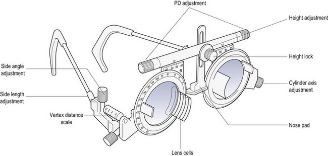
4.2 Focimetry
4.2.2 Procedure
4.2.4 Interpretation
4.2.5 Most common errors
4.3 Interpupillary distance (PD)
4.3.1 Anatomical PD
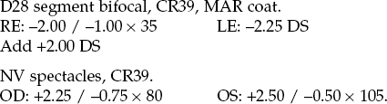
4.3.2 Procedure
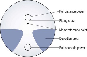
Distance PD
Near PD
4.3.3 Recording
4.3.4 Interpretation
4.3.5 Most common errors
4.3.6 Alternative procedure: Corneal reflection pupillometer
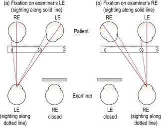
4.4 Phoropter or trial frame?
4.4.1 Advantages of a phoropter
4.4.2 Advantages of a trial frame
4.5 Objective refraction
4.5.1 Comparison of tests
4.5.2 Procedure: Retinoscopy (Summary in Box 4.1)
4.5.3 Adaptations to the standard procedure
 . Concentrate on the central reflex and ignore the reflex at the edges of the pupil.18
4.5.4 Adaptations for older patients
4.5.6 Interpretation
4.5.7 Most common errors
4.6 Monocular subjective refraction
4.6.1 Procedure
4.6.2 Recording
4.6.3 Interpretation
4.7 Best vision sphere (maximum plus to maximum va; MPMVA)
4.7.1 Procedure
4.7.2 Adaptation for older patients
4.7.3 Interpretation
4.7.4 Recording
4.7.5 Most common errors
Refraction and prescribing
 See online video 4.1.