Principles of Ophthalmoscopy
August Colenbrander
No other single invention has shaped the evolution of ophthalmology like the invention of the ophthalmoscope has. Ophthalmoscopy was introduced by Hermann von Helmholtz in December of 1850.1,2 However, Jan Purkinje (known for the Purkinje images) had described the complete technique and published it in Latin in 1823,3 but his audience apparently was not yet ready and his publication went unnoticed. A quarter of a century later, however, the situation changed.
Like many other important inventions, the ophthalmoscope was not based on any radically new concepts. Rather, it combined the appropriate application of various known principles with a recognition of its potential impact and presentation to an appropriate audience. Under the leadership of men like Bowman in London, Donders in Holland, and von Graefe and von Helmholtz in Germany, ophthalmology was emerging as the first organ-based specialty in medicine. Bowman (1816 to 1892) is known for Bowman’s membrane and for his work in anatomy and histology. Donders (1818 to 1889) clarified the principles of refraction and accommodation (1864) and defined visual acuity as a measurable quantity. His coworker Snellen developed the Snellen chart. In Berlin, Albrecht von Graefe (1828 to 1870) was a leader in stimulating the clinical application of new techniques and the careful documentation of new findings. He is remembered for Graefe’s knife and Graefe’s Archives (1854) (one of the first ophthalmic journals), and he founded the German Ophthalmological Society (Heidelberg, 1857). Several workers had tried to visualize the inside of the eye but had fallen short of putting it all together. Kussmaul (known for “Kussmaul’s airhunger”) described the imaging principles in a thesis in 18454 but failed to solve the illumination problem. Cumming5 (1846) in England and Brücke6 (1847) in Germany had shown that a reflection from the fundus could be obtained by bringing the light source in line with the observer, but they failed to solve the imaging problem. Babbage,7 the English mathematician, reportedly constructed an ophthalmoscope in 1847, but his ophthalmologist friend did not recognize the importance and did not publish it until 1854, when von Helmholtz’ instrument was well known.
In the fall of 1850, von Helmholtz tried to demonstrate the inside of the eye to the students in his physiology class. On December 6, he presented his findings to the Berlin Physical Society1; on December 17, he wrote to his father8:
I have made a discovery during my lectures on the Physiology of the Sense-organs, which was so obvious, requiring, moreover, no knowledge beyond the optics I learned at the Gymnasium, that it seems almost ludicrous that I and others should have been so slow as not to see it…. Till now a whole series of most important eye-diseases, known collectively as black cataract, have been terra incognita…. My discovery makes the minute investigation of the internal structures of the eye a possibility. I have announced this very precious egg of Columbus to the Physical Society at Berlin, as my property, and am now having an improved and more convenient instrument constructed to replace my pasteboard affair…
Helmholtz’ monograph on ophthalmoscopy was published in 1851 and soon was widely circulated. The next year there were several important improvements contributed by other workers. Rekoss,9 von Helmholtz’ instrument maker, added two movable disks with lenses for easier focusing. Epkens, working with Donders in Holland,8 introduced a perforated mirror for increased illumination. Ruete10 in Germany did the same and also developed the indirect method of ophthalmoscopy. With these basic components in place, future generations provided technical improvements. In 1913, Landolt11 listed 200 different types of ophthalmoscopes. The most important changes are related to the change from candle light to gas light, to external electric light and, finally, to built-in electric light sources. This chapter concentrates on currently available forms of ophthalmoscopy. For additional information on the history of ophthalmoscopy the reader is referred to references 8 and 12.
Although the older generation found it difficult to adapt to the new instrument, the younger generation did so eagerly. One of them was Eduard von Jaeger (1828 to 1884) from Vienna, best known for his print samples that were based on the print catalogue of the Vienna State Printing House. He was the son of a well-known ophthalmologist and an artistically gifted mother. In 1855, at the age of 27, he published his first atlas; he continued to add to his collection of authoritative fundus paintings until his death in 1884.13
BASIC PRINCIPLES OF DIRECT OPHTHALMOSCOPY
The basic principle of direct ophthalmoscopy is simple (Fig. 1). If the patient’s eye is emmetropic, light rays emanating from a point on the fundus emerge as a parallel beam. If this beam enters the pupil of an emmetropic observer, the rays are focused on the observer’s retina and form an image of the patient’s retina on the observer’s retina. This is called direct ophthalmoscopy.
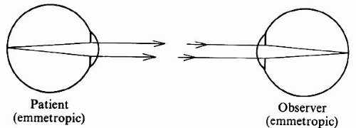 Fig. 1. Imaging in direct ophthalmoscopy. If patient and observer are both emmetropic, rays emanating from a point in the patient’s fundus will emerge as a parallel beam and will be focused on the observer’s retina. |
However, there is a problem with this method: Sufficient light for visualization of the fundus emerges only if the patient’s fundus is properly illuminated. Because of the optics of the eye (Fig. 2), incident light reaches only the part of the fundus onto which the image of the light source falls. Conversely, only light from the fundus area onto which the observer’s pupil is imaged reaches that pupil. The fundus can be seen only where the observed and the illuminated areas overlap; in the emmetropic eye this can happen only if the light source and the observer’s pupil are aligned optically. Under normal conditions this does not happen, and the pupil normally appears black. How a reflection can be seen under abnormal conditions is discussed later in this text.
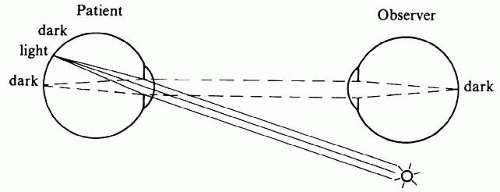 Fig. 2. The illumination problem in direct ophthalmoscopy. If the light source and the observer are not aligned optically, the observer views a part of the fundus that is not illuminated. |
There are several ways in which optical alignment of the illuminating and observing beams can be accomplished (Fig. 3). Von Helmholtz solved the problem with a semireflecting mirror made up of several thin parallel pieces of glass (see Fig. 3A). Epkens and Ruete used a perforated concave mirror, which places illuminating light rays all around the observation beam (see Fig. 3B). A modification of this arrangement is used in the fundus camera. Most hand-held instruments now have a small mirror or prism (see Fig. 3C), which uses the lower half of the patient’s pupil for illumination and the upper half for observation.
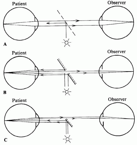 Fig. 3. Illumination methods in direct ophthalmoscopy. A. Illumination with semireflecting mirror (Helmholtz). B. Illumination with perforated mirror (Epkens, Ruete). C. Illumination with mirror or prism (modern). |
FIELD OF VIEW IN DIRECT OPHTHALMOSCOPY
If the patient’s fundus is properly illuminated, the field of view is limited by the most oblique pencil of light that can still pass from the patient’s pupil to the observer’s pupil (Fig. 4). In direct ophthalmoscopy the retinal point that corresponds to this beam can be found by constructing an auxiliary ray through the nodal point of the eye.11 The point farthest from the centerline of view that can still be seen is determined by the angle α, that is, the angle between this oblique pencil and the common optical axis of the eyes.
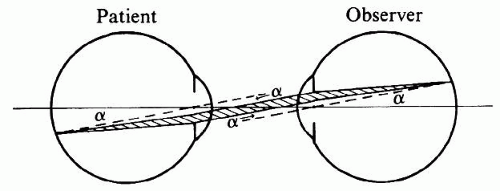 Fig. 4. Field limits in direct ophthalmoscopy. The maximum field of view is determined by the most oblique pencil of rays (shaded) that can still pass from one pupil to the other. |
Angle α, and therefore the field of view, is increased when the patient’s or the observer’s pupil is dilated or when the eyes are brought more closely together.
The more peripheral pencils of light use ever-smaller parts of each pupil. This means that, even if the patient’s fundus is uniformly illuminated, the luminosity of the fundus image gradually decreases toward the periphery, so that there is no sharp limitation to the field of vision. In practice, therefore, the effective field of vision is determined by the illuminating system not by the viewing system. Most ophthalmoscopes project a beam of light of about one disc diameter.
EXTENDING THE FIELD—INDIRECT OPHTHALMOSCOPY
Even with appropriate illumination, direct ophthalmoscopy has a small field of view. Figure 5 shows that of four points in the fundus, points one and four cannot be seen because pencils of light emanating from these points diverge beyond the observer’s pupil. To bring these pencils to the observer’s pupil, their direction must be changed (Fig. 6). This requires a fairly large lens somewhere between the patient’s and the observer’s eye. This principle was introduced by Ruete10 in 1852 and is called indirect ophthalmoscopy to differentiate it from the first method, in which the light traveled in a straight, direct path from the patient’s eye to the observer.
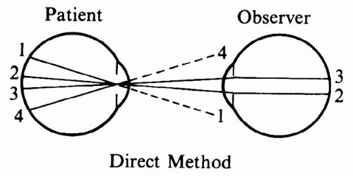 Fig. 5. Limited field of view in the direct method. Peripheral pencils of light do not reach the observer’s pupil. |
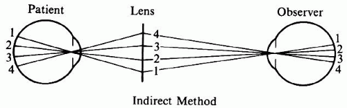 Fig. 6. Extended field of view in the indirect method. The ophthalmoscopy lens redirects peripheral pencils of light toward the observer. |
The use of the intermediate lens has several important implications that make indirect ophthalmoscopy more complicated than direct ophthalmoscopy.
The primary purpose of the ophthalmoscopy lens is to bend pencils of light toward the observer’s pupil. Figure 6 also demonstrates one of the most characteristic side effects of this arrangement: Compared with the image in direct ophthalmoscopy, the orientation of the image on the observer’s retina is inverted. For the novice, this often causes confusion in localization and orientation. Figure 6 further shows that in this arrangement the patient’s pupil is imaged in the pupillary plane of the observer. In optical terms the pupils are in conjugate planes. This fact is useful later in this discussion.
FIELD OF VIEW IN INDIRECT OPHTHALMOSCOPY
The field of view in indirect ophthalmoscopy is determined by the rays emerging from the patient’s eye that can be caught in the ophthalmoscopy lens. With optimal placement of the lens and of the observer’s eye, the distance from the patient’s eye to the lens is only slightly more than the focal length of the lens. (The exact distance will be calculated later.) The field of view, therefore, is determined by the ratio of lens diameter and focal length. This ratio can also be written as a product:
Lens diameter/Focal length = Lens diameter × dioptric power
This provides an easy formula for comparing the field of view of various lenses.
Given lenses of equal power, a larger lens provides a wider field of view. If lenses have equal diameters, a stronger lens provides a wider field of view; however, because stronger lenses often have a smaller diameter, a stronger ophthalmoscopy lens does not always provide a larger field. A 20-diopter (D) lens of 30 mm provides about the same field of view as a 30-D lens of 20 mm or as a 13-D lens of 45 mm (because 20 × 30 = 30 × 20 = ±13 × 45).
IMAGING IN INDIRECT OPHTHALMOSCOPY
Figure 6 shows that light emerging from the patient’s fundus is directed toward the observer’s eyes. It does not specify whether the observer sees a focused image or just an unstructured red reflex. Figure 7 traces the rays within one of the pencils of light from the patient’s fundus to the observer’s retina.
 Fig. 7. Imaging in the indirect method. A pencil of rays (shaded) is traced from the patient’s fundus to the observer’s retina. An intermediate, inverted image of the patient’s fundus is formed in the focal plane of the ophthalmoscopy lens. The observer must accommodate on this image. |
If the patient is emmetropic, the pencils emerging from the eye are composed of parallel rays, but this changes once the pencils pass through the ophthalmoscopy lens. In fact, because the rays within each pencil enter the ophthalmoscopy lens with zero vergence, they are brought to a focus in the focal plane of the ophthalmoscopy lens. Proceeding beyond that point, the rays within each pencil are divergent.
Considering all pencils emerging from the patient’s eye together, an aerial image of the patient’s fundus will be formed in the focal plane of the ophthalmoscopy lens. This image is inverted with respect to the patient’s fundus, and it is this image that the observer is viewing. To focus the aerial image on his or her own retina, the observer must accommodate for the aerial image plane and hence cannot approach too closely.
It may be useful to recall the difference between tracing of pencils and tracing of rays. In any optical system, tracing of pencils is necessary to determine the limits of the field of view; tracing of rays is necessary to determine the position of the image plane.Optical diagrams may confuse the uninitiated, because they generally trace only one ray per pencil (see Figs. 5 and 6) and may use theoretic auxiliary rays beyond the physically existing pencils (see Fig. 4) to facilitate the construction of object and image planes.
In direct ophthalmoscopy, peripheral pencils of light are increasingly cut off by the observer’s and patient’s pupils (see Fig. 4). In indirect ophthalmoscopy (see Fig. 7) this does not happen; only the observer’s pupil limits the diameter of the pencils that reach the observer’s retina. The apparent luminosity of the fundus image, therefore, is constant throughout the field (provided, of course, that the fundus is illuminated evenly). This is one reason fundus cameras are built around the imaging principle of indirect ophthalmoscopy.
In summary, the purpose of the ophthalmoscopy lens in indirect ophthalmoscopy is to redirect diverging pencils of light emerging from the patient’s pupil toward the observer’s eye. In doing so, the lens also focuses parallel rays within each pencil into an inverted aerial image of the patient’s fundus. The existence of an inverted aerial image is one of the most prominent and unavoidable characteristics of indirect ophthalmoscopy.
Another characteristic of indirect ophthalmoscopy is that it requires a considerable distance between the patient and the observer. This is in contrast to direct ophthalmoscopy, in which close approximation is advantageous. When tuberculosis and other respiratory infections were common, the arm’s length distance between observer and patient was considered an additional advantage of the indirect method. In Europe, indirect ophthalmoscopy has been the preferred method; direct ophthalmoscopy is used mainly for additional detail. In the English-speaking countries the opposite has occurred; indirect ophthalmoscopy did not become popular until the introduction of the binocular indirect ophthalmoscope by Schepens.14
The indirect method offers a wider field of view than does direct ophthalmoscopy, but this advantage is at the expense of decreased magnification. How do the two methods compare?
MAGNIFICATION IN DIRECT OPHTHALMOSCOPY
If the patient and the observer are both emmetropic, the optical diagram for direct ophthalmoscopy (see Fig. 4) is completely symmetric. It is easy to see that the size of the retinal image in the observer’s eye will equal the size of the fundus detail seen. In this sense the magnification is 1/1, that is, the image of the patient’s disc will measure one disc diameter on the observer’s retina.
Another more conventional way of defining magnification is to compare the observer’s view of a given object with the view that would be obtained when looking at the same object from a standard distance. The usual standard for comparison is 25 cm. How much larger does the patient’s disc appear than does the disc of a dissected eye viewed at 25 cm?
For this calculation the optics of the reduced eye (discussed elsewhere in these volumes) may be compared with a linen tester or other hand-held magnifier of 60 D (Fig. 8). Such a lens allows a viewing distance of 0.0167 m, 15 times shorter than the reference distance of 0.250 m. Thus, the viewing angle is 15 times larger, and the magnification is said to be 15 times.
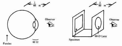 Fig. 8. Magnification in the direct method. Viewing the fundus through the optics of the patient’s eye (60 D in the reduced eye) can be compared with viewing a specimen under a 60-D magnifier. |
If the patient and the observer are not both emmetropic, the calculations are more complex. Axial length of both eyes, refractive power of both eyes, and the position of the compensating lenses in the ophthalmoscope must all be considered; the eyes of myopic patients have extra plus power and the ophthalmoscope must carry a negative lens. This combination, in part, acts as a Galilean telescope for the observer, and fundus details are seen larger. In aphakia the reverse happens: fundus details are seen smaller, as through a reversed Galilean telescope.
In direct ophthalmoscopy the image on the observer’s retina is about as large as the fundus detail viewed and is 15 times larger than it would be if the same fundus detail were viewed from 25 cm.
An additional 2× magnification can be achieved by placing a small Galilean telescope on the ophthalmoscope, but fundus microscopy with the slit lamp and a contact lens is a better way to achieve this level of magnification.
MAGNIFICATION IN INDIRECT OPHTHALMOSCOPY
Magnification in indirect ophthalmoscopy can best be understood if broken down into two components: magnification from fundus detail to aerial image and magnification from aerial image to the observer’s retinal image. Magnification in the first step depends on the power of the ophthalmoscopy lens; magnification in the second step depends on the observation distance.
If the patient is emmetropic, the aerial image is formed in the focal plane of the lens (compare Fig. 7). Figure 9 shows that
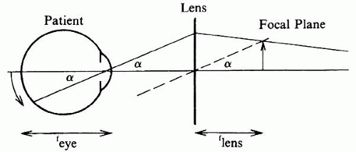 Fig. 9. Magnification of the aerial image in the indirect method. Aerial image size is found through construction of an imaginary, auxiliary ray (dotted line). Fundus detail f × sin α. Aerial image is f × sin α. |
Aerial image/Fundus detail = flens × sin α/feye × sin α = flens/feye
converting from focal length to diopters and assuming 60 D as the power of the eye
Aerial image/Fundus detail = flens × sin α/feye × sin α = flens/feye = Deye/Dlens = 60/lens power
Thus the aerial image formed by a 20-D lens will be 60/20, or three times larger than the corresponding fundus detail; with a 30-D lens it will be 60/30, or two times larger.
When the aerial image is viewed from 25 cm, no further magnification is involved, because 25 cm is the reference distance for magnification. A 25-cm viewing distance from the aerial image requires 4 D of accommodation on the part of the observer; a more common viewing distance is 40 cm, requiring 2.5 D of accommodation. Changing from 25 cm to 40 cm reduces the observer’s retinal image size by 25/40 or 5/8.
Combining both steps we obtain the following: With a 20-D lens and a distance of 25 cm from aerial image to observer, the patient’s disc is seen 3 timeslarger than the disc of a dissected eye at 25 cm. With direct ophthalmoscopy this would have been 15 times larger. Indirect ophthalmoscopy in this case provides five times less magnification than does direct ophthalmoscopy. For a 40-cm viewing distance the magnification becomes 5/8 × 3, which is approximately 2, or 8 times less than direct ophthalmoscopy.
Similar calculations can be made for other lenses. Figure 10 summarizes data for lenses of 30 D, 20 D, and 13 D. As the magnification becomes less, the area of the patient’s fundus that can be imaged on a given area of the observer’s retina increases quadratically; for instance, 8 times less linear magnification potentially results in a 64-times larger area seen. Whether this potential is realized depends on the factors mentioned in the discussion of the field of view in both methods: width of the illuminating beam in direct ophthalmoscopy and diameter of the ophthalmoscopy lens in indirect ophthalmoscopy.
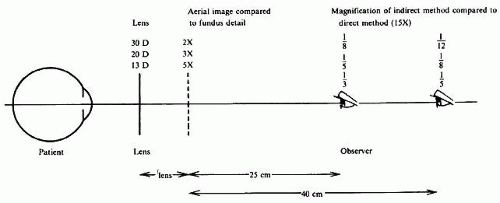 Fig. 10. Total magnification in the indirect method. Total magnification depends on lens power and observation distance and is always less than in the direct method.
Stay updated, free articles. Join our Telegram channel
Full access? Get Clinical Tree
 Get Clinical Tree app for offline access

|