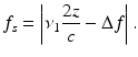
Fig. 7.1
Basic configuration of OFDR optical system
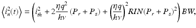
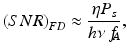
The detector current can be expressed as
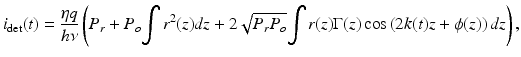
where η is the detector sensitivity, q the quantum of electric charge (1.6 × 10⁻¹⁹ C), hν the single photon energy, P r the optical power reflected from the reference arm at the photodetector, and P o the optical power illuminating the sample. The third term represents the interferometric signal, and the first and second terms contribute to the noninterference background. Here, z is the axial coordinate where z = 0 corresponds to zero optical path length difference between the two interferometric arms, r(z) and ϕ(z) are the amplitude and phase of the reflectance profile of the sample, respectively; Γ(z) is the coherence function of the instantaneous laser output; and k(t) = 2π/λ(t) is the wavenumber which is varied in time monotonically by tuning of the laser. It can be readily seen that the interferometric signal current is related to the reflection profile via the Fourier transform relation. In practice, the detector output is digitized and sampled into a finite number of data points, and a discrete Fourier transform (DFT) is performed to construct an axial scan or A-line.
(7.1)
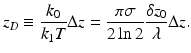
For a wavelength-swept laser with a Gaussian-profile spectral envelope, the axial resolution is given by [11]
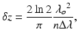
where λ ο is the center wavelength, Δλ is the full width at half maximum (FWHM) of the spectral envelope (tuning range), and n is the group refractive index of the sample. The depth range Δz in the Fourier domain is given by [4]

where δλ = Δλ/N s is the sampling wavelength interval and N s is the number of samples within FWHM range of the spectrum Δλ. The sampling interval should be smaller than the instantaneous linewidth of the source; otherwise, the amplitude of the coherence function will decay with z, limiting the usable ranging depth.
(7.2)
(7.3)
7.2.2 Detection Sensitivity
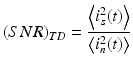
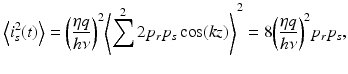
For simplicity, let us consider the case of a single reflector located at z = z 0 with reflectivity r 2. We assume that the linewidth is sufficiently narrow so that Γ(z) = 1 within the depth range. The signal current, i s (t), can be expressed as
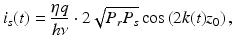
where P s = r 2 P 0 denotes the optical power reflected from the sample at the photodetector. In reality, the detector current consists of both signal and noise components such that i(t) = i s (t) + i n (t). The well-known expression for the noise power 〈i n 2〉 is given by [12]
where the three terms on the right-hand side represent thermal noise, shot noise, and the relative intensity noise (RIN) of the source (polarized), respectively. Brackets < > denote a time average, ith the detector noise current, RIN the relative intensity noise given in unit of Hz−1, and BW the detection bandwidth. The detection bandwidth can be chosen equal to half the sampling rate as specified by the Nyquist.
(7.4)
(7.5)
For simplicity, let us assume a square-profile spectral envelope and 100 % tuning duty cycle, i.e., the output power of the source is constant in time. Let F s and F n denote the Fourier transform samples of signal and noise currents, i s and i n , respectively, following DFT via
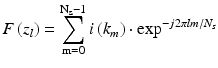
(7.6)
Note that the wavenumber and axial coordinate are conjugates to each other through DFT. In the Fourier domain, the absolute square of the peak value of F s at z l = z 0 is proportional to the reflectivity. Parseval’s theorem, ∑ F 2 = N s ∑ i 2, holds for both signal and noise. In the case of Nyquist sampling (i.e., the sampling rate is equal to twice the detection bandwidth), the sampled data of noise current are mutually uncorrelated [6, 7]. Therefore, the noise power level in the Fourier domain is given by 〈F n 2〉 = N s 〈i n 2〉. On the other hand, the signal power F s 2 is zero except at z l = z 0. Since there are two peaks corresponding to positive and negative frequency components, using |F s (z 0)|2 = (N s 2/2)〈i s 2〉 leads to
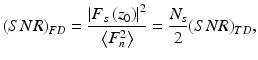
where
(7.7)
(7.8)
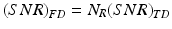
Here, the latter is defined as the ratio of the signal and noise power in the time domain. These equations indicate that frequency-domain ranging provides an SNR improvement by a factor of N s /2 compared with time-domain ranging [13]. A similar expression to Eq. 7.7 has been identified by Leigeb et al. [7] and de Boer et al. [6] for spectral-domain OCT and also by Choma et al. [5] for OFDR using a wavelength-swept laser.
It can be shown that Eq. 7.7 is valid for a more general case where the tuning duty cycle is less than 100 %, the source’s spectral envelope has a Gaussian profile, and the sampling range spans beyond the FWHM of the source spectrum. In this case, N s is the number of sampling points within the FWHM of the source and the optical powers, P r and P s , would be the time-average value over one tuning cycle. For a shot-noise-limited system, Eqs. 7.5 and 7.7 with P s ≪ P r lead to
where f A is the A-line rate which is the same as the tuning rate of the source. Therefore, the effective detection bandwidth in OFDR is equal to the A-line scan rate instead of the detector bandwidth.
(7.9)
Equation 7.7 can also be expressed in terms of the number of spatially resolvable points in a ranging depth, N R = Δz/δ z, as
(7.10)
This expression compares the SNR of two ranging methods, time domain and frequency domain, at the same imaging speed (A-line rate), axial resolution, and ranging depth. Note that a time-domain OCT system requires a detection bandwidth of N R f A , whereas the effective noise bandwidth of OFDI is f A .
The sensitivity is defined as the reflectivity that produces signal power equal to the noise power. Therefore, it follows from Eq. 7.9 and P s = r 2 P 0 that
![$$ Sensitivity\left[ dB\right]=-10\ \log \left(\frac{\eta {P}_0}{h\nu \kern0.2em {f}_{\kern-0.2em A}}\right) $$](/wp-content/uploads/2017/03/A76297_2_En_8_Chapter_Equ11.gif)
(7.11)
The relative intensity noise (RIN) of polarized thermal light is proportional to the reciprocal of the linewidth [12] and would have a value of −97 dB/Hz for a linewidth of 0.06 nm (10 GHz). In general, RIN of laser light is different from that of thermal light. However, laser light consisting of many longitudinal modes with random phases would exhibit a peak RIN level similar to that of thermal light of the same linewidth. The mode hopping associated with wavelength tuning and mode competition contributes to the frequency dependence of RIN. The RIN level of our laser had a peak value of approximately −100 dB/Hz near DC frequency, decreasing to −120 dB/Hz at 5 MHz. To reduce the source’s RIN, dual-balanced detection was employed [14]. The differential current of two InGaAs detectors D1 and D2 was amplified using transimpedance amplifiers (TIA, total gain of 56 dB) and passed through a low-pass filter (LPF) with a 3-dB cutoff frequency at 5 MHz and excess voltage loss of 3 dB. The common-noise rejection efficiency of the receiver was approximately 25 dB in the range between DC and 5 MHz. In addition to RIN reduction, the balanced detection provides multiple benefits; it suppresses self-interference noise [7] originating from multiple reflections within the sample and optical components; it also improves the dynamic range and reduces fixed-pattern noise by greatly reducing the strong background signal from the reference light.
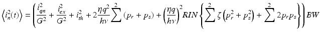
In the case of dual-balanced detection, the signal power in Eq. 7.4 can be expressed as
where p r = P r /2 and p s = P s /2 denote the reference and signal power per photodiode. The noise power expression in Eq. 7.5 can be modified to
(7.12)
(7.13)
Here, the first and second terms are introduced to take into account the quantization noise and excess electrical noise generated in the DAQ board. G denotes the total gain of the receiver. The third term is the thermal noise of the dual-balanced receiver. The fourth term represents the total shot noise which is a sum of the shot noise from the individual photodiodes. The fifth term expresses the RIN noise with ζ denoting the common-mode rejection efficiency of the balanced receiver. It should be noted that the dual-balanced receiver provides RIN suppression only to the RIN component associated with intraband self-beating. The cross-beating noise, as a result of the incoherent interference between p r and p s , is not canceled. When ζ ≪1, the cross-beating RIN component may not be negligible compared to the self-beating RIN component although p s is weaker than p r . In practice, the first two terms, quantization and excess noise, can be made negligible by choosing a sufficiently high gain (e.g., G = 2 × 10⁵) [13].
7.3 Instrumentation
7.3.1 Light Source and Interferometer
Light sources appropriate for OFDI are discussed in detail in Chap. 12, “Linear OCT Systems”. In the context of this chapter, it will be sufficient to briefly consider the relevant laser characteristics and their implications for high-speed imaging. The laser specifications having the greatest significance for OFDI include wavelength sweep range, sweep repetition rate, linearity of sweep, power, and instantaneous linewidth. The primary relevance of the source wavelength-scanning range for OFDI is axial resolution. For imaging at a center wavelength of 1.3 μm where attenuation in biological tissues is low, a scanning range of more than 100 nm is required to achieve a resolution comparable with previous-generation time-domain OCT systems. Consideration of laser repetition rate is similarly straightforward; the image A-line acquisition rate is directly determined by the laser repetition rate. For imaging at speeds of 100 frames per second, a repetition rate of >50 kHz is required. The linearity of the wavelength-scan, however, is somewhat more subtle. Although nonlinear scanning can, in principle, be accommodated by sophisticated acquisition electronics, the ideal laser for OFDI would provide a highly linear k-space scan. Fortunately, achieving all of these specifications is now possible while simultaneously producing sufficient power in order to preserve clinically relevant sensitivity. Typical performance specifications have been on the order of 10s of mW of polarized laser power.
As described in the previous sections of this chapter, the instantaneous linewidth of the laser determines the ranging depth and the falloff of sensitivity with ranging depth. For many OFDI applications, an instantaneous linewidth of 0.1 nm-0.2 nm (roughly 20–40 GHz) is sufficient. It is interesting to note that this linewidth is significantly greater than that provided by most wavelength-swept lasers that preceded the development of OFDI. Prior swept lasers were primarily developed for high-resolution spectroscopy where single-longitudinal-mode oscillation is essential and linewidths below 1 MHz are routinely achieved. Relaxing the linewidth specification allows for more rapid tuning without concerns for longitudinal mode hopping.
In order to achieve the greatest possible ranging depth, it would be preferred to use the full instantaneous coherence length of the laser source. Equation 7.4, however, indicates that positive and negative depths, relative to the reference delay, are encoded by the same magnitude of frequency. Since it is not possible to distinguish between a positive and negative electrical frequency in conventional interferometry, OFDI requires alternative interferometer designs to break the depth degeneracy and achieve full ranging depth. Solutions to this challenge can be achieved through the use of quadrature interference signals. Approaches have included active- or passive-phase biasing using piezoelectric actuators [15], birefringent plates [16], and fused fiber 3 × 3 couplers [17]. These techniques can unfold otherwise overlapping images associated with positive and negative depths, but tend to leave residual artifacts due to the difficulty of producing stable quadrature signals. An alternative approach uses an optical frequency shifter in the interferometer to provide a constant frequency shift of the detector signal. This method allows both sides of the coherence range to be used without crosstalk and doubles the ranging depth. The same concept has been described previously in the context of 1-dimensional optical frequency-domain reflectometry using rotating birefringent plates [19] at 58 Hz or a recirculating frequency-shifting loop [16].
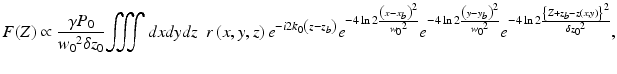
Figure 7.2 depicts a simplified OFDI system comprising a wavelength-swept source, a single-mode-fiber interferometer employing an optical frequency shifter in the reference arm, a photodetector, and a signal processor [18]. Since the optical glass used in acousto-optic frequency shifters can exhibit high dispersion, it is preferable to insert a matching glass within the interferometer sample arm. With a round-trip frequency shift of Δf in the reference arm and an interferometer path length difference (or depth) of z, the detector signal can be expressed as
![$$ {i}_s(t)=2\eta \sqrt{P_r(t){P}_s(t)}{\displaystyle \int \sqrt{R(z)}\kern0.5em G\left(\left|z\right|\right) \cos \left[\frac{4\pi }{c}\nu (t)z+\phi (z)+2\pi \Delta ft\right]}dz, $$](/wp-content/uploads/2017/03/A76297_2_En_8_Chapter_Equ14.gif)
where η denotes the quantum efficiency of the detector; P r (t) and P s (t) the optical powers of the reference and sample-arm light, respectively; R(z) the reflectivity profile of the sample; G(|z|) the coherence function corresponding to the fringe visibility; c the speed of light; ν(t) the optical frequency; and ϕ(z) the phase of backscattering. For linear tuning, i.e., ν(t) = ν 0 − ν 1 t, the frequency of the detector signal is given by
(7.14)
(7.15)
Fig. 7.2
OFDI system schematic
A signal frequency of zero (DC) corresponds to a depth z = cΔf/(2ν 1). Therefore, by choosing Δf and ν 1 to have opposite signs, the zero signal frequency can be made to point to a negative depth.
7.3.2 Sampling and Data Processing
Nonlinearity in the frequency sweep of the laser results in a chirping of the signal at a constant depth and causes a degradation of axial resolution [16, 19]. As a solution to this problem, the detector signal may be sampled with nonlinear time intervals compensating for the frequency chirp. Alternatively, the detector signal can be sampled with a constant time interval if the sampled data is remapped to a uniform ν-space by interpolation prior to discrete Fourier transform (DFT) [20]. Both methods have been demonstrated to yield a transform-limited axial resolution given by the tuning spectral range of the source.
These methods, however, are not directly applicable in the frequency-shifting technique. Both nonlinear sampling and the interpolation method result in artificial chirping of the frequency shift, leading to suboptimal axial resolution. Alternatively, a modified interpolation method based on frequency shifting and zero padding can be used to achieve nearly transform-limited axial resolution over the entire ranging depth. An exemplary algorithm includes the following:
Step 1. Obtain N samples of the signal with uniform time interval during each wavelength sweep of the source.
Step 2. Calculate DFT of N data points in the electrical frequency domain.
Step 3. Separate two frequency bands below and above Δf corresponding to negative and positive depths, respectively.
Step 4. Shift each frequency band such that the zero depth is aligned to the zero electrical frequency.
Step 5. Apply zero-padding to each frequency band and calculate inverse DFT resulting in an array of increased number of samples in the time domain with smaller time interval for each frequency band.
Step 6. Interpolate each array in the time domain into a uniform ν space using a mapping function calibrated to the nonlinearity of the source with linear interpolation. The mapping function can be obtained using an unbalanced interferometer.
Step 7. Calculate DFT of each interpolated array.
Step 8. Combine the two arrays (images) by shifting the array index.
Yun et al. [18] have demonstrated that the above algorithm, coupled with the interferometer design of Fig. 7.2, can be used to achieve a twofold increase of the effective ranging depth of OFDI. Measurements of the system axial resolution indicated that the interpolation algorithm compensated for laser tuning nonlinearity and yielded transform-limited resolution throughout the extended ranging depth.
7.4 Motion Artifacts
Image artifacts resulting from motion have been important topics of research in nearly all medical imaging modalities because they may degrade the image quality and cause inaccurate clinical interpretation of images [21–23]. Artifacts can arise when an object being imaged (sample) is moved during data acquisition but is assumed stationary in the image reconstruction process. In each imaging modality, motion artifacts can present in different forms and with different magnitudes. Understanding basic motion effects in a particular imaging method is an essential step toward the development of techniques to avoid or compensate resulting artifacts.
In the following analysis, it is assumed that the source emits light according to k(t) = k 0 + k 1 t, where k = 2π/λ is the wavenumber, λ is the optical wavelength, t is the time spanning from −T/2 to T/2, and T is the wavelength-sweep period or equivalently A-line period. Further, we assume a Gaussian tuning envelope given by
![$$ {P}_{out}(t)={P}_0\kern0.5em \exp \left[-4 \ln 2{t}^2/{\left(\sigma T\right)}^2\right], $$](/wp-content/uploads/2017/03/A76297_2_En_8_Chapter_Equ16.gif)
where P out (t) denotes the output power of the source and σT the full width at half maximum (FWHM) of the tuning envelope. Equation 7.16 also describes the Gaussian spectral envelope of the source, where σk 1 T corresponds to the FWHM tuning range in wavenumber. Let (x, y, z) denote the coordinate of a reference frame fixed to the sample, r(x, y, z) represents the complex-valued backscattering coefficient of the sample which is characterized by both local variations of the refractive index and the round-trip attenuation of light in the sample, g(x, y, z) denotes the intensity profile of the probe beam normalized to ∬ g dx dy = 1, and (x b , y b, z b ) denotes the coordinates of the probe beam at zero path length difference of the interferometer. For a Gaussian beam with a large confocal parameter, the intensity profile is given by
![$$ g\left(x,y,z\right)\approx \frac{4 \ln 2}{\pi {w_0}^2} \exp \left[-4 \ln 2\left({x}^2+{y}^2\right)/{w_0}^2\right], $$](/wp-content/uploads/2017/03/A76297_2_En_8_Chapter_Equ17.gif)
where w 0 denotes the full width at half maximum (FWHM) of the beam profile. The explicit dependence of the OFDI signal on the intensity profile, g, rather than an electric field profile of the probe beam can be understood by considering the mode field profile of the sample-arm fiber, which is by definition given by Eq. 7.17 at the sample location. The amplitude of the backscattered light received by the sample-arm fiber is determined by an overlap integral between the scattered field and the mode field.
(7.16)
(7.17)
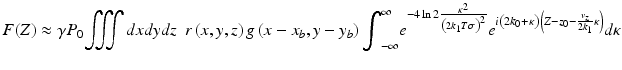
It has been shown [24] that the complex-valued depth profile can be represented using the above notation as
where δz 0 = 41n2/(k 1 Tσ) denotes the FWHM axial resolution neglecting the effect of truncation of a Gaussian spectrum. Equation 7.18 states that the amplitude of F(Z) is proportional to a coherent sum of all backscattered light from a coherence volume that has a size w 0 × w 0 × δ z 0 and is located at a depth Z in the sample.
(7.18)
7.4.1 Axial Motion
Figure 7.3a depicts a situation with an axially moving sample and probe. The interference signal is solely dependent on the relative motion between the scatterer and the probe beam; sample motion is identical to probe motion with the opposite velocity. Therefore, we will assume a stationary probe and consider a sample moving at a uniform velocity without loss of generality.
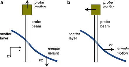
Fig. 7.3
Geometry for considering the effects of axial and transverse motion
The signal in the presence of axial motion can be obtained by substituting z b (t) = z − z 0 − v z t into Eq. 7.18 where z 0 = z–z b (0) denotes the mean path length difference and v z the axial velocity of the sample. The depth profile is obtained via the Fourier transform:
![$$ \propto \frac{\gamma {P}_0}{{w_0}^2\delta z}{\displaystyle \iiint dxdydz}\kern0.5em r\left(x,y,z\right){e}^{-i2{k}_0{z}_0}{e}^{-4\mathrm{In}2\frac{{\left(x-{x}_b\right)}^2}{{w_0}^2}}{e}^{-4 \ln 2\frac{{\left(y-{y}_b\right)}^2}{{w_0}^2}}{e}^{-4 \ln 2\frac{{\left\{Z-\left[{z}_0+\left({k}_0/{k}_1T\right)\Delta z\right]\right\}}^2}{\delta {z_0}^2\left(1+4{\sigma}^2\Delta {z}^2/\delta {z_0}^2\right)}} $$](/wp-content/uploads/2017/03/A76297_2_En_8_Chapter_Equ20.gif)
where Δz = v z T denotes the axial displacement of the sample during a single A-line acquisition time. Equation 7.20 illustrates two effects of axial motion. First, depth in the image is given by Z = z 0 + z D , where
(7.19)
(7.20)