Fig. 53.1
(a) Schematic of distal end of the dual-modal endoscope design. (b) Photograph of a precision-cut metal enclosure (of an outer diameter 2.4 mm) with minimal beam blockage (i.e., less than 5 %). (c) A cross-sectional photograph of the custom dual-clad fiber, with dimensions labeled (9 μm core, 180 μm large inner cladding, and 200 μm outer cladding). (d) A photograph of the constructed endoscope of an overall diameter of 2.9 mm including the housing transparent sheath (Figure reprinted with permission from Biomedical Optics Express, Optical Society of America)
The overall working distance of this endoscope, as defined as the distance between the focal point and the outer surface of the metal enclosure, is governed by the distance between the GRIN lens and the microreflector. The working distance was measured to be 1.9 mm and the lateral resolution was ∼13.7 μm. The distal end of the endoscope has an overall diameter of 2.4 mm with a rigid length of 14.4 mm. Furthermore, for practical use, the entire endoscope was enclosed in an off-the-shelf transparent plastic sheath (outer diameter 2.9 mm) as shown in Fig. 53.1c. We were able to easily adjust the beam focus outside of the transparent sheath by tuning the distance between the microreflector and fiber-lens assembly, and the final beam focus was set at 1.6 mm outside of the sheath.
53.2.1.2 System Design
Thus far, we have discussed the endoscope design that enables the dual-modality OCT and fluorescence imaging; however, some of the challenges in the implementation of this imaging system are in how to combine and separate of light from two individual imaging modalities. The OCT module consists of a swept-source which is a home-built 40 kHz Fourier-domain mode-locking (FDML) fiber laser operating at a center wavelength of 1,305 nm with a 3 dB spectral bandwidth of ∼140 nm. The OCT module also includes a Mach-Zehnder interferometer (MZI) to generate a calibration signal and a dual-balanced detector is utilized. The fluorescence imaging module consists of an argon ion laser at 488 nm for excitation and a photomultiplier tube (PMT) for detection.
There are a few methods by which to combine two light sources through free-space optics, a fiber-optic coupler or other fiber-optic devices. Using free-space optics is the most straightforward method, and this method has been widely used in benchtop systems. For endoscopy, this method proves to be bulky with a large footprint and is not portable enough to be used for clinical or animal imaging. For this reason, a fiber-optic approach is favored. In this case, since the OCT backscattered light will go through the coupling device, it is important to maintain a low roundtrip loss. We used a wavelength division multiplexer (WDM) which works at both the near infrared OCT source wavelengths and visible fluorescence excitation wavelengths, shown in Fig. 53.2.
Fig. 53.2
Schematic of the dual-modality system capable of performing endoscopic OCT and fluorescence imaging simultaneously. FDML Fourier-domain mode-locking fiber laser, OC optical coupler (OC1 95/5, OC2 70/30, OC3 50/50), MZI Mach-Zehnder interferometer, CIR Circulator, PC polarization controller, BD balanced detector, WDM wavelength division multiplexer, DCFC double-clad fiber coupler, PMT photomultiplier tube, F band-pass filter; Green, multimode fiber (MMF); blue/red, double-clad fiber (DCF); black, single-mode fiber (SMF-28e) (Figure reprinted with permission from Biomedical Optics Express, Optical Society of America)
The WDM allowed us to obtain a minimal insertion loss of 0.5 dB for OCT, and although the efficiency of transmitting fluorescence excitation was sub-optimal, we were able to obtain an ∼60 % efficiency. This efficiency allowed us to have 3-mW fluorescence excitation light incident on the sample which was sufficient for fluorescence imaging.
The final challenge in the construction of this system lay in how to effectively separate the OCT backscattered light from the fluorescence emission light that are both collected by and transmitted through the endoscope. This posed a great challenge since we opted to implement an entirely fiber-optic platform. Our solution was to use a customized DCF coupler that consists of a single-mode fiber (SMF-28e) port, a multimode fiber port, and a DCF port.
On the forward path (from the source to the sample), the DCF coupler couples the OCT source and excitation source light traveling in the single-mode fiber to the single-mode core of the DCF (with a loss of 0.8 dB and 2.2 dB, respectively). On the return path (from the sample to the detector), the OCT backscattered light and fluorescence emission travel through both the core and large inner cladding of the DCF in the endoscope. The DCF coupler allows the light traveling in the core of the DCF to be coupled back into the single-mode fiber port and the light traveling in the inner cladding of the DCF to be separated into the multimode fiber port. In this way, the OCT backscattered light seamlessly returns to the OCT system through fiber optics, where only light at the OCT source wavelengths are able to pass through the circulator and interfere with light from the OCT reference arm. Similarly the fluorescence emission, which travels mostly in the inner cladding of the DCF is coupled into the multimode fiber port and detected by a photomultiplier tube (PMT). Additionally, to avoid any potential leakage of fluorescence excitation light backscattered into the endoscope and transmitted through the inner cladding, band-pass filters were placed before the PMT. Both OCT and fluorescence signals are collected simultaneously during imaging and are digitized, displayed, and stored in a synchronized fashion.
53.2.2 Dual-Modality OCT and Two-Photon Fluorescence Endoscopy
Similar to the OCT and single-photon fluorescence imaging platform, the endoscope is a key component through which simultaneous high-resolution OCT and two-photon fluorescence imaging is performed. Here, an en face imaging system is considered for both OCT and two-photon fluorescence. We will start with the endoscope design, followed by the description of the system-level integration.
53.2.2.1 Endoscope Design
A lateral beam scanning mechanism is required in the endoscope for performing en face OCT and TPF imaging (which is conventionally realized by using galvanometric mirrors in a benchtop system). Here, we adopt our previously developed, piezoelectrically actuated, fiber-optic resonant scanner to achieve rapid lateral beam scanning [7, 27]. Although the movement of the piezoelectric (PZT) actuator is imperceptible, the attached fiber cantilever driven by the PZT actuator at or close to its resonant frequency could generate a large lateral deflection. According to a cantilever beam model, the zeroth-order resonant frequency of a fiber cantilever can be expressed as:
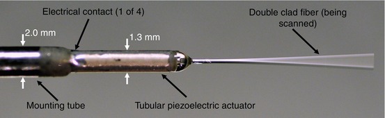
where E, ρ, R, and L are the Young’s modulus, mass density, radius, and the length of the fiber cantilever, respectively. Figure 53.3 shows a photograph of a tubular, four-quadrant monolithic PZT beam scanner with a fiber threaded through the central hole. The overall diameter of the scanner including a housing unit can be as small as 2.0 mm. With an exposed fiber length of about 10 mm, the mechanical resonant frequency of the fiber cantilever of a 125 μm diameter is calculated as ∼1 kHz based on Eq. 53.1 that is consistent with experimental results.
(53.1)
Fig. 53.3
Photograph of 1.3-mm-diameter four-quadrant, tubular piezoelectric actuator mounted on a 2.0-mm-diameter base. The double-clad fiber is threaded through the actuator and is being scanned
Depending on the driving frequency applied on the PZT actuator, either spiral or Lissajous scanning pattern can be achieved at the cantilever tip (as shown in Fig. 53.4). The spiral scan requires two orthogonal driving waveforms of the resonant frequency modulated by a slowly varied amplitude waveform leading to a circular field of view (Fig. 53.4a) [28]. Such a scanning pattern is easy to implement on tubular piezoelectric actuators, and image reconstruction is also quite simple. However, it suffers from nonuniform spatial sampling due to the fact that the tangential velocity of the scan trajectory increases as it moves from the center of the field of view. In practice, this leads to oversampling in the center and undersampling at the periphery. On the other hand, Lissajous scan can be implemented with two driving waveforms with constant amplitudes but shifted frequencies that are close to the resonant one, leading to a rectangular field of view (Fig. 53.4b) [29]. In order to obtain a closed curve, the frequency ratio must be rational. In practice, the ratio of the two driving waveform frequencies is usually chosen to be close to 1. Although Lissajous scanning provides a better spatial sampling density, the complex trajectory makes reconstruction computationally intensive and sensitive to any perturbation.
Fig. 53.4
Trajectories of fiber-optic cantilever tip. (a) Spiral pattern. (b) Lissajous pattern with a frequency ratio of 40:41
Optical fiber is another critical component in the endoscope. Here, a customized double-clad fiber (DCF) was employed. The core diameter of the DCF is ∼8 μm, similar to that of the standard single-mode fiber (i.e., SMF-28e®), ensuring both 1,550 nm (the excitation wavelength for TPF) and 1,310 nm (the center wavelength of the OCT light source), can be delivered in single mode through the core, hence achieving small focused spot size on the sample. The inner cladding of the DCF (ϕ175 μm) is able to effectively collect the two-photon fluorescence signal by utilizing its large area and NA. The NA of the DCF core and inner cladding were 0.14/0.12 (at 1,310 nm/1,550 nm) and 0.267 (at 1,550 nm), respectively.
The focusing lens represents a significant challenge in the integrated endoscopic system. The lens needs to have a high NA and low geometric aberrations for obtaining a near diffraction-limited focal spot size. Chromatic aberration should be taken into account due to wavelength difference between OCT, two-photon excitation, and emission wavelengths. In this system, the light from DCF cantilever tip was focused onto the sample by a miniature aspherical compound lens with a maximum NA of 0.8 and a magnification of ∼0.22 (along the direction of fiber to sample). A minimal chromatic focal shift of the micro compound lens from the OCT wavelength (1,310 nm) to the two-photon excitation wavelength (1,550 nm) was measured to be ∼11 μm.
53.2.2.2 System Design
Figure 53.5 shows the dual-modal system schematic, which integrates the OCT and TPF imaging modalities, capable of performing endoscopic OCT and TPF imaging simultaneously [30]. In the OCT module, the light from a fiber-coupled superluminescent diode of a 13-mW output power with a central wavelength of 1,310 nm and a 3-dB bandwidth of 80 nm was delivered into a Michelson interferometer. In the TPF module, a 1,550 nm passive mode-locked amplified fiber laser was used as the excitation source. The laser generated ultrashort pulses (i.e., ∼300 fs with a repetition rate of 42.5 MHz) with a maximum average power of ∼155 mW. It operated in the soliton regime so that the laser pulses remain relatively unchanged inside the single-mode fiber (e.g., SMF-28e® or any fiber with the similar dispersion characteristics as SMF-28e®). Therefore, the TPF system does not require any specific dispersion compensation. A high-isolation wavelength division multiplexer (WDM) made of SMF-28e® was placed in the OCT sample arm to combine the 1,310 nm OCT light source with the 1,550 nm TPF excitation laser.
Fig. 53.5


Schematic of TPF/OCT multimodal endomicroscope system. BD balanced detector, C circulator, CL coupling lens, DCF double-clad fiber, DM dichroic mirror, ENDO miniature endoscope, EOM electro-optic modulator, FC fiber coupler, LP long pass filter, M mirror, PMT photomultiplier tube, RSOD rapid scanning optical delay line, WDM wavelength division multiplexer (Figure reprinted with permission from Optics Letters, Optical Society of America)
Stay updated, free articles. Join our Telegram channel
Full access? Get Clinical Tree
