Geometrical Optics
Edmond H. Thall
The discipline of geometrical optics deals with image formation by optical instruments. Physical optics (see elsewhere in these volumes) deals with the nature of light itself (e.g., electromagnetic waves and photons). In contrast, geometrical optics deals with the various pathways light travels as it moves from an object, through an optical system, and, ultimately, arrives at the image. Interestingly, image properties depend primarily on the routes light travels rather than on the nature of light per se.
The refracting lane is an ideal laboratory for demonstrating the principles of geometrical optics. Light a candle and extinguish all other illumination. Stand a few meters from the candle and hold a + 4.00 D spherical convex trial lens about 25 cm in front of a sheet of plain white paper and observe the flame’s inverted image. In the same way, the ocular media produce images on the retina. The clinician should understand the factors that influence the image’s characteristics (e.g., size, location, and so forth), the effects of pathology on the image, and how to use this information both diagnostically and therapeutically.
This chapter presents the theory of geometrical optics and then gives examples illustrating the application of theory to clinical practice. The treatment is largely qualitative. Mathematical details are in the Appendix.
BASIC DEFINITIONS
The word lens may refer to a single piece of glass (or other material) or to a combination of individual lenses assembled to function as a unit. Element refers specifically to an individual lens. Figure 1 shows a high-quality camera lens consisting of six elements.
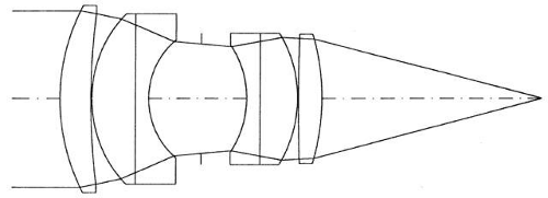 Fig. 1. A common photographic lens consisting of six individual elements. |
A rotationally symmetric optical system has an axis of symmetry called the optical axis (Figs. 1 and 2). Rotating the system about the axis does not alter the imaging characteristics. Rotationally asymmetric systems do not have an axis. Look through a -1.00 D spherical trial lens. Rotate the lens and notice that the scene does not change. Replace the spherical lens with a prism or cylinder and observe how the scene changes as the lens rotates. Thus, cylinders and prisms are not rotationally symmetric.
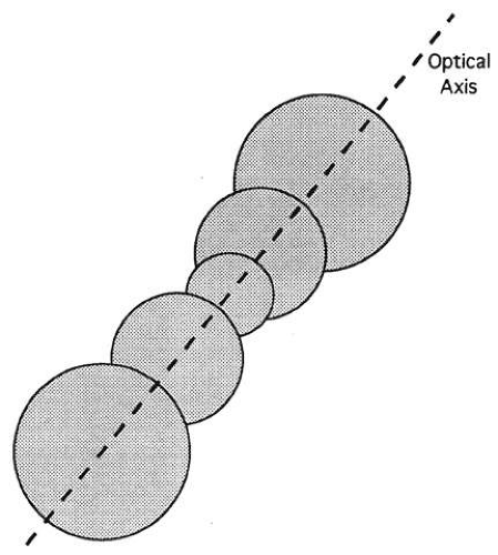 Fig. 2. Most optical systems consist of several lenses symmetrically arranged along a common axis. |
A vertex is any intersection of the axis with a lens surface (Fig. 3). At the vertex, the axis is normal (i.e., perpendicular) to the lens surface.
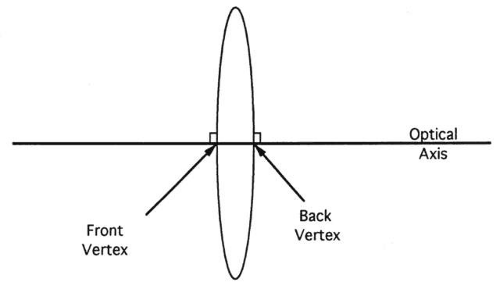 Fig. 3. The vertices are the intersections of the lens surfaces with the axis. The axis is perpendicular to the lens surfaces at the vertices. |
OBJECTS
An object may be luminous or nonluminous. A luminous object or source produces light and is visible in otherwise total darkness. Every point on a luminous object radiates light in all directions (Fig. 4). Nonluminous objects do not produce light and are visible only when illuminated by a source. When light strikes a point on a nonluminous object, it is diffusely reflected or scattered in all directions (Fig. 5).
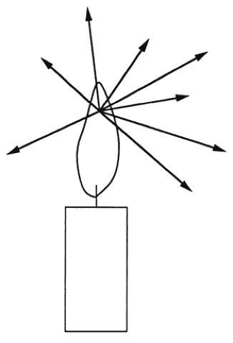 Fig. 4. Every point of a luminous object (e.g., candle flame) radiates light in all directions. |
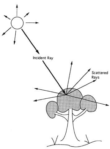 Fig. 5. Nonluminous objects scatter light in all directions. |
Diffuse reflection should not be confused with specular reflection. In specular reflection, light symmetrically rebounds in a single direction instead of scattering in many directions (Fig. 6). From the standpoint of geometrical optics, the most important characteristic of an object, whether luminous or nonluminous, is that every point of the object radiates light in all directions. Surfaces that reflect specularly are mirrors, not objects.
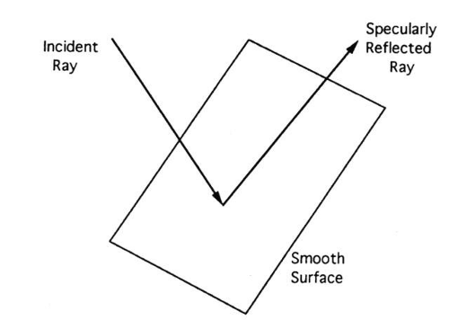 Fig. 6. In specular reflection, the incident light symmetrically rebounds from the surface. |
A point source (Fig. 7) occupies no volume (i.e., a point in the mathematical sense) and radiates light in all directions. Point sources do not exist, but conceptually, objects are simply a collection of point sources. Every object point is a point source radiating in all directions. Point sources simplify the analysis of optical systems by making it possible to deal with one object point at a time.
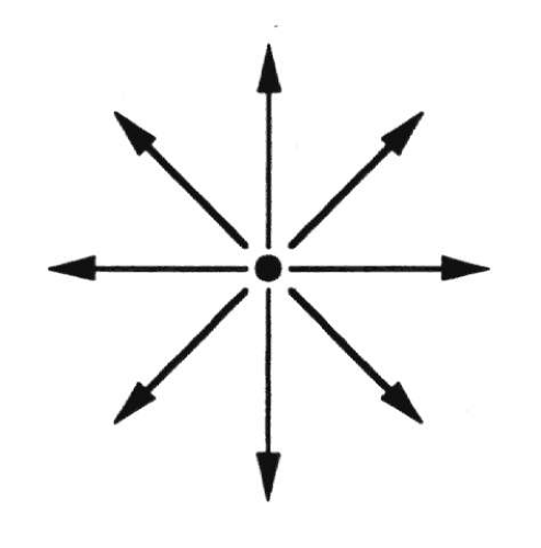 Fig. 7. A point source radiates light in all directions. |
THE STIGMATIC IMAGE
Each point on a screen (e.g., piece of paper) placed near an object receives light from many object points (Fig. 8), and no image appears. An appropriate lens placed between screen and object redirects light so that each point on the screen receives light from a single object point (Fig. 9), thereby producing an image. Without the lens, light from a single object point distributes over the entire screen, mixing with light from every other object point. With the lens, however, light from a single object point falls on a single screen point and does not mix with light from any other object point.
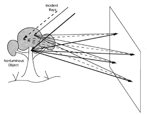 Fig. 8. Each point on the screen receives light from multiple object points. No image is produced. |
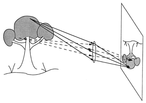 Fig. 9. The lens redirects light so that each point on the screen receives light from only one object point. An image is produced. |
The one-to-one correspondence between object and image points is the essential feature of the stigmatic image. The word stigmatic derives from the Greek “stigma,” meaning stylus or point, and emphasizes the point-to-point nature of the stigmatic image.
Imaging is a two-step process. In the first step, an object distributes light in all directions. This is an important step. If an object radiates light in only one direction, then it will be visible from only one vantage point (Fig. 10). Scattering light makes objects visible from many directions simultaneously (Fig. 11). Although beneficial, scattering necessitates a second step, the redirection of light by an optical system to produce an image.
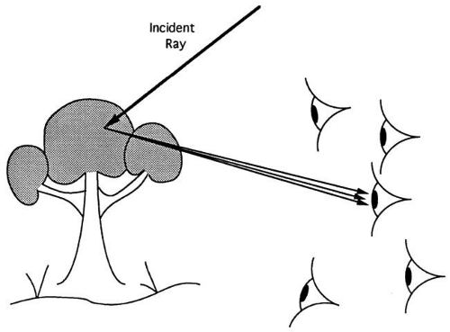 Fig. 10. If the object scattered light in only one direction, it would be visible to only one observer. |
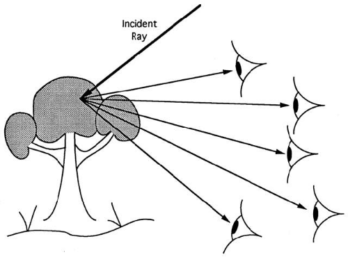 Fig. 11. Objects scatter in many directions and thus are visible to several observers simultaneously. |
THE IDEAL IMAGE
Besides stigmatism, there are other desirable image properties. The image of a flat object that is normal to the axis should, likewise, be flat and normal to the axis. Some lenses produce stigmatic, but curved, images. The technical term for this is field curvature. Photographic film is usually flat. A photograph of a curved image taken with flat film is out of focus at the edges (Figs. 12 and 13). Of course, the retina is curved, but the macula is flat. Only the macula is capable of high acuity, so field curvature is undesirable in the eye.
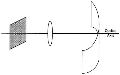 Fig. 12. Non-ideal optical systems may image planes perpendicular to the axis as curved surfaces. If this is a camera using a flat piece of film, the photograph will be blurry at the edges. |
 Fig. 13. Photograph was taken using a + 4.00 D trial lens. The image is out of focus at the edges because of field curvature. |
Figure 14 shows a photograph of an Amsler grid. The image is stigmatic and flat, but distorted. The image does not preserve the spatial relationship of the object points. For that matter, enlarged, reduced, or inverted images do not preserve the spatial relationship of the object points either. However, an enlarged image differs from the original object by only a scale factor. Distortion is a greater disruption of the image. No simple change in scale can make a distorted image resemble the object.
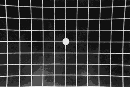 Fig. 14. Photograph of an Amsler grid. Straight lines appear to curve toward the center because of the pincushion distortion. The effect is most pronounced at the edges. |
Field curvature and distortion are not always undesirable. Photographers use distortion for aesthetic effects. Panoramic cameras have field curvature but use curved film to compensate. Nevertheless, geometrical optics defines the ideal image as stigmatic and free of field curvature or distortion. The ideal image may be enlarged, reduced, or inverted with respect to the object.
RAYS
A ray is an abstract representation of a light path. An arrow indicates the propagation direction. Rays represent paths, not the light moving along those paths. A ray gives no indication of the physical characteristics (e.g., intensity, wavelength, and so forth) of the light traveling along the ray.
It may seem somewhat pedantic, but lenses bend light, not rays. When a ray strikes the surface of a lens or mirror, it does not deviate. The light moving along the ray changes direction and begins to move along a new ray. Rays continue straight through the surface of a mirror or a lens, but the light does not (Fig. 15). Rays extend infinitely in both directions. Light travels over only a segment of the ray. The distinction between a ray and the light moving along a ray becomes important later when dealing with pupils and virtual images. For clarity, illustrations usually show only the portion of a ray over which light travels, but rays are straight and infinite in extent.
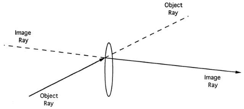 Fig. 15. Technically, a ray never deviates. The ray extends as a straight line to infinity. Lenses (or mirrors) do not change the ray’s direction. At the lens, the light traveling along the ray changes direction. The light stops moving along the object ray and begins moving along the image ray. |
It must be noted that it is common practice and more economical to use statements such as “the lens bends the ray” instead of “the lens bends light traveling along the ray.” Of course, the implication is that the light bends, not the ray.
Any ray that intersects the object point is an object ray. Similarly, image rays intersect the image point. Object rays represent light before it has entered the optical system, and image rays represent light after it emerges from the system. Every object ray entering an optical system gives rise to a unique image ray. Thus, every object ray is associated with a unique image ray, and vice versa.
ADDITIONAL DEFINITIONS
Before proceeding, some additional definitions will be helpful. An ideal lens is a rotationally symmetric optical system that produces an ideal image of any object. At this point the imaging properties of the lens are the main concern, and there is no need to worry about how many elements are in the lens or any other aspects of its construction. Consequently, ideal lenses are illustrated as “black boxes” (Fig. 16).
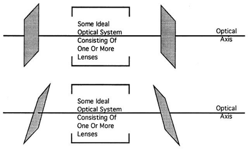 Fig. 16. Planes perpendicular to the optical axis are imaged (top), ideally, as planes perpendicular to the axis. Planes (bottom) tilted with respect to the axis are imaged, ideally, as planes tilted with respect to the axis. |
Objects are usually three-dimensional, but it is easier to describe optical properties using flat objects confined to planes. An object plane is normal to the axis and contains an object (see Fig. 16). Every point in an object plane is a potential object point or point source. Image planes are normal to the axis, and every point in the image plane is a potential image point.
Conjugate refers, in a rather general way, to the object-image relationship. Let O and O′ be, respectively, an object point and its image. O is conjugate to O′. Similarly, O′ is conjugate to O.
Collectively, O and O′ constitute a pair of conjugate points.
Transverse magnification is the ratio of image height to object height. Two aspects of magnification are confusing. In common parlance, magnification implies enlargement, but in optics, magnification applies to any image whether larger or smaller than the object. Images are scale models of the object, and magnification is the scale factor. Magnification also indicates the image’s orientation with respect to the object. A negative magnification indicates an inverted image. For example, a magnification of -2 means the image is inverted and twice the size of the object. A magnification of 0.5 indicates that the image is upright and half the size of the original.
Transverse magnification applies to linear dimension. Thus, a 1-inch-wide, 2-inch-high object magnified by a factor of two gives a 2-inch-wide, 4-inch-high image. Both the height and width change by a factor of two, increasing the image’s area by a factor of four.
PROPERTIES OF IDEAL LENSES
The ideal lens produces a one-to-one correspondence between object points and image points. Consequently, no two object points share the same image point. Thus, necessarily, the image of every object point has a different location in space.
Consider two points P and Q imaged by an ideal lens to conjugates P′ and Q′, respectively (Fig. 17). One particular ray happens to go through both object points P and Q. This object ray will produce an image ray that must pass through both image points P′ and Q′. Light originating from P travels along the ray and must reach P’. Similarly, light originating from Q travels along this ray and must reach Q′. So, the image ray associated with this particular object ray must go through both image points.
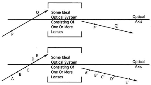 Fig. 17. P′ and Q′ are the images of P and Q, respectively (top). An object ray that intersects both object points P and Q must produce an image ray that intersects P′ and Q′. Extending the reasoning, every point on the object ray has an image somewhere on the image ray (bottom). |
This reasoning extends to every point on an object ray. Every point on an object ray has a unique image point, and the image ray associated with the object ray passes through all of these image points. The object ray and its associate image ray are conjugate. To summarize, light moving along an object ray enters an optical system, deviates, and emerges, traveling along an image ray. Every point on the object ray must have an image somewhere on the image ray.
From a clinical viewpoint, the most important property of ideal lenses deals with object and image planes. Associated with every object plane is a unique image plane. Every point in the object plane has an image somewhere in the associated image plane (i.e., the object and image planes are conjugate). No two object planes share the same image plane; every object plane has an image plane in a different location (Fig. 18). This property seems inconsistent with daily experience. To be seen clearly, the image must be on the retina. According to this property, only one object can have an image plane on the retina at any one time; despite this fact, everything in a scene seems to be in focus simultaneously.
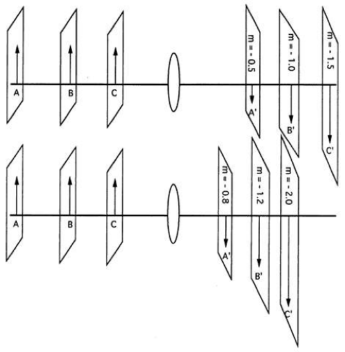 Fig. 18. Every object plane has a different image plane. A map can be constructed for an ideal imaging system showing the image locations associated with various object locations. Note the changes in magnification. Different (ideal) imaging systems give different maps. (m, magnification) |
How can the properties of imaging systems be reconciled with common experience? First, the impression that all objects in a scene are in focus simultaneously is not correct. Carefully observe a scene with both near (about 18 inches) and distant (about 6 feet) objects. Notice that when the near objects are clear, the far objects are blurry, and vice versa. We have a mistaken notion that everything is in focus simultaneously because we pay attention only to part of a scene at any one time. As we shift our attention, the eye keeps various objects in focus by varying accommodation. Nevertheless, many objects are simultaneously in focus despite being various distances from the observer. This is due to depth-of-focus, a property of optical systems discussed later.
In any case, image position changes as object position changes. Magnification also changes with object position. For example, there is only one object position that gives an image with a magnification of 2. Any magnification is attainable with an ideal lens, but only if the object is in the correct location. A sort of map can be constructed that identifies the image plane location for various object planes (see Fig. 18). The map can also indicate magnification.
Image position also depends on lens power. Repeat the candle and lens demonstration using different power lenses while maintaining a constant distance between candle and lens. Again, the image position varies with lens power. The maps depicted in Figure 18 vary for every different ideal lens.
An important aspect of geometrical optics is the ability to predict image position and size theoretically (given the object position and lens power) without going to the trouble of doing the experiment.
INFINITE CONJUGATES AND FOCAL PLANES
As the distance between an object point and lens increases, the object rays tend to become parallel (Fig. 19). It takes a little imagination, but rays from an infinitely distant object point are parallel. When the infinitely distant object point is on the optical axis, the object rays will be parallel to each other and parallel to the axis. If the distant object point is not on the axis, the object rays are still parallel to each other, but not parallel to the axis (Fig. 20).
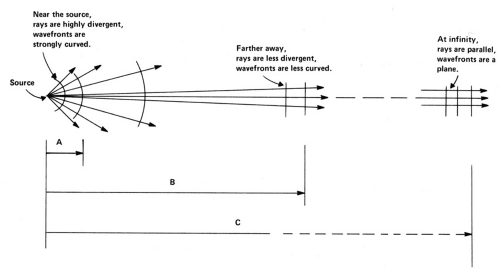 Fig. 19. The amount of divergence of the light is inversely proportional to the distance from the source. If the distance is expressed in meters, the vergence is in units of diopters: 1\Distance in Meters = Diopters. Since A < B, 1\A > 1B. (The light at distance A has more vergence than that at B.) Since C = ∞, 1\∞ = 0. For example, if we go far enough, the vergence is zero. |
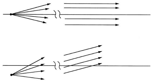 Fig. 20. Rays from an infinitely distant object point on the axis yield rays parallel to the axis (top). Rays from an infinitely distant object off axis yield rays parallel to each other but not parallel to the axis (bottom). |
When the rays emerging from a lens are strongly convergent, the image is close to the lens. The less divergent the rays, the farther the image from the lens. If the image rays are parallel, the image point is at infinity. Image rays parallel to each other and also parallel to the axis give an infinitely distant image point on the axis. Image rays parallel to each other but not parallel to the axis give infinitely distant image points off-axis.
Objects that are not infinitely distant but far away give rays that are nearly parallel. Objects 20 feet (6 m) or more distant give rays so close to parallel that, for clinical purposes, they may be considered at infinity.
Object rays parallel to each other and to the axis produce image rays that converge at the secondary focal point. Because the object rays arose from an infinitely distant object point, the secondary focal point is the image of an on-axis object point at infinity. The secondary focal plane is normal to the axis through the secondary focal point. Off-axis points at infinity image at various points on the secondary focal plane (Fig. 21).
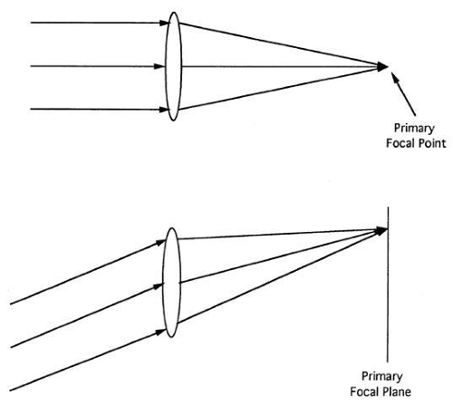 Fig. 21. Rays from an on-axis object point at infinity image at the focal point. Rays from an off-axis object point at infinity image on the focal plane. |
An object point at the primary focal point produces image rays that are parallel to each other and the axis (Fig. 22). Thus, the primary focal point’s image is on-axis at infinity. The primary focal plane is normal to the axis through the primary focal point. Object points on the primary focal plane give image rays that are parallel to each other but not necessarily parallel to the axis (see Fig. 22).
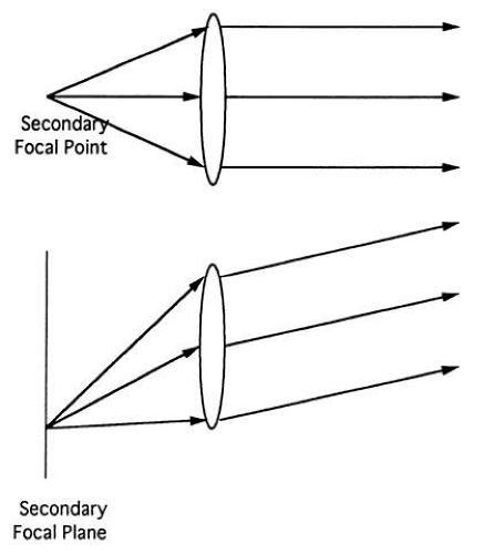 Fig. 22. Object rays from the secondary focal point emerge as image rays parallel to each other and to the axis (top). Object rays from a point on the secondary focal plane emerge as image rays parallel to each other but not necessarily to the axis (bottom). |
GRAPHICALLY LOCATING THE IMAGE
This section describes a means of locating the image using a graphical technique called ray sketching. This method is easy to use but requires a rather detailed explanation.
Image location partially depends on the properties of the lens. Thus, it is impossible to locate an image by any method without some specific information about the lens. In ray sketching, the cardinal points contain the lens information.
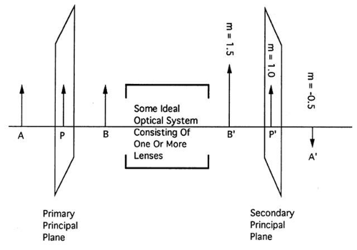 Fig. 23. The principal planes are the planes of unit magnification (m). Thus, an object placed in the primary principal plane will be imaged upright and actual size at the secondary principal plane. |
The nodal points are another pair of useful landmarks located on the axis. An object ray passing through the primary nodal point is conjugate to an image ray passing through the secondary nodal point, and both rays make the same angle with the optical axis (Fig. 24). There are no nodal planes associated with the nodal points.
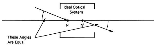 Fig. 24. An object ray passing through the primary nodal point (N) emerges at the same angle from the secondary nodal point (N’). The ray is displaced but unchanged in direction. |
Collectively, the principal, focal, and nodal points constitute the cardinal points of the optical system. All the information about the lens and its imaging properties is contained in the position of these points on the axis. Fundamentally, the only difference between two ideal imaging systems is the location of their cardinal points.
RAY SKETCHING
The ray sketching method for locating an image can now be described. Starting with an ideal optical system, the task is to determine image location and size for a given object (Fig. 25).
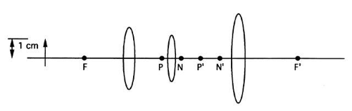 Fig. 25. An optical system showing the location of the cardinal points and an object. Where is the image formed and what is the magnification? |
STEP 1.
Ignore the presence of the lenses because the locations of the cardinal points completely determine the properties of an ideal system. If necessary, redraw the object and optical system to scale using just the optical axis and cardinal points. Draw the principal planes through the principal points and normal to the axis (Fig. 26).
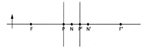 Fig. 26. Ray sketching. Step 1: Redraw the system to scale omitting the lenses. Draw the principal planes normal to the axis and through the principal points. |
STEP 2.
Pick some point on the object but not on the optical axis. Rays emanate from this point in all directions. In particular, one of these rays will be parallel to the optical axis. Draw the ray parallel to the axis from the object point to the primary principal plane (Fig. 27). Conceptually, this ray extends backward to infinity; in principle, this ray goes through the axial object point at infinity.
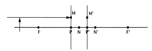 Fig. 27. Step 2: Select an object point not on the optical axis and draw the ray parallel to the axis. Designate the point where this ray meets the primary principal plane as M. The image of M is located on the secondary principal plane at M’. |
STEP 3.
The object ray drawn in step 2 goes through two important object points: 1) the axial object point at infinity and 2) a point on the primary principal plane (point M). The image ray must go through the images of these two object points. The image of M is M’. M’ is a point on the secondary principal plane at the same height above the axis as point M because the principal planes are conjugate with a magnification of 1. Thus, the image ray must go through M’ and the secondary focal point. The image ray is drawn through these two points (Fig. 28).
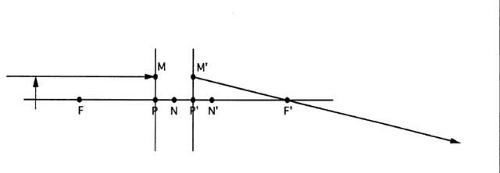 Fig. 28. Step 3: Draw the image ray through points M’ and F′ and extend it. |
STEP 4.
Many other rays emanate from the object point, including one that goes through the primary image point F. Draw this ray and extend it to the principal plane (Fig. 29).
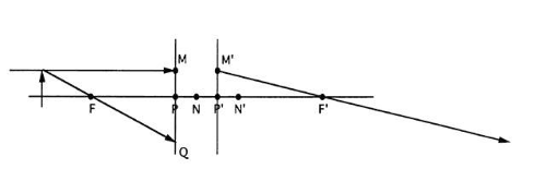 Fig. 29. Step 4: Draw another ray from the object point through the primary focal point F and extend it to the primary principal plane. Designate Q as the point of intersection with the primary principal plane. |
STEP 5.
The ray drawn in step 5 must be conjugate to an image ray parallel to the axis (because the object ray goes through the primary focal point). The image ray must also pass through Q′, the image of Q. Draw the second image ray through Q′ and parallel to the axis (Fig. 30).
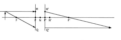 Fig. 30. Step 5: Draw the image of the ray drawn in step 4. The image ray is parallel to the axis and through the point Q′. The two image rays intersect at the image point. |
STEP 6.
All the rays from the object point must intersect at the image point, so the two rays just drawn must also intersect at the image point. The intersection of the two image rays locates one image point. The rest of the image is drawn normal to the axis (Fig. 31).
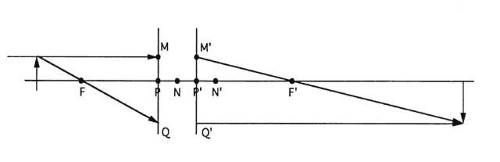 Fig. 31. Step 6: Draw the rest of the image perpendicular to the axis and through the image point. Because the drawing is to scale, the magnification can be found by measuring the object and image heights and taking the ratio. The magnification for this example is m = -1.6. The negative sign indicates the inverted image. |
STEP 7.
Only two rays are necessary to locate the image, but it may help to draw a third ray from the object point to the primary nodal point N (Fig. 32).
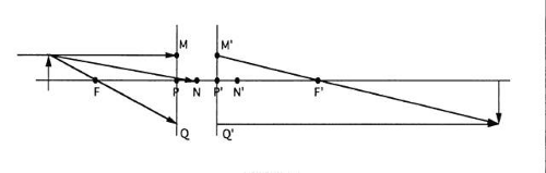 Fig. 32. Step 7: As a check, draw a third ray from the object point to N. |
STEP 8.
The image ray conjugate to the object ray drawn in step 7 goes through the secondary nodal point and is parallel to the object ray (Fig. 33). This ray should intersect the other two at the image point.
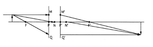 Fig. 33. Step 8: This ray emerges from N′ without a change in angle. If the drawing is correct, then this ray should intersect the other two image rays at a common point. |
With a little practice, ray sketching becomes second nature. However, an understanding of why ray sketching works is more important than facility with the technique. The value of ray sketching is more pedagogical than practical. Ray sketching is not used on a daily basis, but it is helpful when one is confronted with a new or unfamiliar optical system.
To summarize, rays emerge from an object point in all directions, and there is no easy way to determine the image rays associated with most of these object rays. However, for three special object rays, the conjugate image rays can be determined with the aid of the cardinal points. These three special object rays are: 1) the ray parallel to the axis, 2) the ray through the primary focal point F, and 3) the ray through the primary nodal point N. The intersection of the image rays conjugate to these object rays locates the image.
It is important to realize that ray sketching does not give the actual path of a ray within the lens itself. Ray sketching gives only the final image ray associated with a particular object ray. Figure 34 compares a ray sketch with the actual path of light traversing a thick lens. Although ray sketching does not give the true light path, the ray that finally emerges does coincide with the image ray predicted by ray sketching.
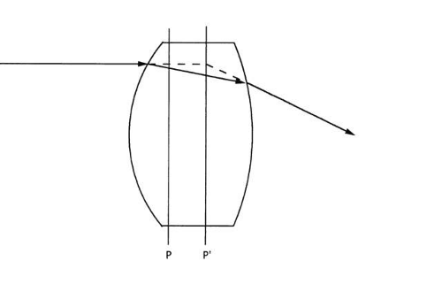 Fig. 34. Comparison of a ray sketch with the actual path a ray follows through a lens. The path is not the same as the ray sketch, but the final image rays do coincide. |
In other words, ray sketching gives the correct final answer, but the intermediate details are wrong. With use of a different technique called ray tracing, it is possible to determine the exact path light follows. Ray tracing requires a detailed description of the optical system (not just the cardinal points) and considerable calculation. The strength of ray sketching is that it skips all the intermediate details and gives the correct result without calculation. The gain in simplicity comes at the expense of detailed information about the light path within the lens system itself.
LOCATING IMAGES BY VERGENCE
In the examples described so far, light diverges from the object point and converges to the image point. Vergence is a quantitative measure of light’s degree of convergence or divergence. As noted previously, when distance from an object point increases, divergence decreases (see Fig. 19). Similarly, as distance from the image point increases, convergence decreases. Thus, vergence is inversely proportional to distance from an object or image point. By convention, divergent light has a negative vergence, and convergent light has a positive vergence.
Vergence is a property of a ray, and every point on a ray has a different vergence. To give a concrete example, consider an object point 25 cm away from the primary principal plane of an ideal lens and 5 cm in front of the primary focal plane (Fig. 35). When rays from the object point cross the primary focal plane, they have a vergence of -20.00 D. The vergence is negative because the light is divergent. The number 20.00 is the reciprocal of the distance in meters between the object point and focal plane (5 cm = 0.05 m, 1/0.05 = 20). The uppercase “D” is the standard abbreviation for diopter. The diopter is the standard unit of vergence used clinically. When the light reaches the primary principal plane, the vergence is -4.00 D. Again, the vergence is negative because the light is divergent. The number 4 is the reciprocal of the distance between the object point and principal plane (0.25 m).
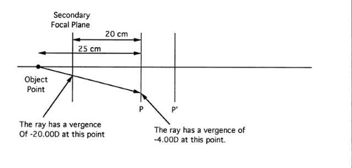 Fig. 35. Every point on a ray has a different vergence. The vergence of any particular point is inversely proportional to the distance from (or to) the object (or image) point. |
Upon emerging from the lens, the light’s vergence has changed. An ideal lens is simply a vergence changer. The power of the lens specifies the amount of vergence change the lens produces. The lens in Figure 35 has a power of + 5.00 D. Thus, light with a vergence of -4.00 D has a vergence of + 1.00 D (= -4.00 D + 5.00 D) at the secondary principal plane. The image is 1 m behind the secondary principal plane. The distance is found by taking the reciprocal of the vergence.
To give a second example, if the object point in Figure 35 were 25 cm from the primary principal plane, then light (at the primary principal plane) would have a vergence of -4.00 D. The lens changes the vergence by + 5.00 D, giving light at the secondary principal plane a vergence of + 1.00 D. The image is 100 cm behind the secondary principal plane. The Appendix gives additional examples.
Vergence is the reciprocal of distance. Units of length, or distance, include inches, meters, centimeters, and so forth. Therefore, the units of vergence are reciprocal inches (in)-1), reciprocal meters (m)-1), reciprocal centimeters (cm)-1), and so forth. Vergence is expressible in any of these inverse units. However, lens power and vergence add only when both are in the same units. To avoid confusion, it is universal clinical practice to use units of inverse meters for both vergence and lens power. The unit of diopter was created as a matter of convenience. By definition, one diopter equals one inverse meter.
It is conventional practice to round vergence to two decimal places, and the sign, whether positive or negative, should always be written. In most mathematical work, plus signs are redundant and not written, but the most common mistake in vergence calculations is inadvertently dropping a minus sign. Always writing the sign helps to prevent this.
Transverse magnification can be calculated by use of vergence. The ratio of object vergence to image vergence gives the transverse magnification. In the first example of this section, the transverse magnification is -4.00 (= -4.00 D/+ 1.00 D). In the second example, magnification is -2/3 (= -2.00 D/+ 3.00 D).
Finally, note that parallel light rays neither converge nor diverge, and thus have a vergence of zero diopters. By convention, light from objects or images more than 20 feet away is so close to parallel that it is assigned a vergence of zero.
VIRTUAL IMAGES AND VIRTUAL OBJECTS
Where is the image of an object 12.5 cm in front of a + 3.00 D lens? The object vergence is -8.00 D (at the lens), so the image vergence is -5.00 D. The negative vergence means that the image rays emerging from the lens are still divergent. The ray sketch is shown in Figure 36. Unlike previous examples, the lens does not have enough power to convert the divergent object rays into convergent image rays. Granted, the image rays are less divergent than the object rays (by three diopters in this case), but the image rays remain divergent. There is no real image, and this can be verified by use of a candle and trial lens.
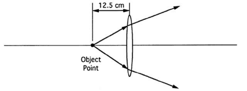 Fig. 36. The object point is so close to the lens that the image rays emerging from the lens are divergent. |
Suppose a + 6.00 D lens is placed 5 cm behind the original + 3.00 D lens. The divergent light emerging from the first lens reaches the second lens, which does have enough power to converge light and form a real image. What is the location of the image formed by the second lens?
To answer this question, it is necessary to know the vergence of light incident on the second lens. Light has a vergence of -5.00 D when it emerges from the first lens, but the vergence changes as the light travels from the first lens to the second lens. The change in vergence produced simply by light moving from one place to another within the same medium is the vergence change on transfer. Because of the vergence change on transfer, it is necessary to determine the vergence of the light incident on the second lens.
Vergence is always related to the distance between an object or image point and some point of interest on the ray (such as the point where the ray meets the lens). Thus, to determine the vergence of the light incident on the second lens, the image rays emerging from the first lens must be associated with some image point. The image point is found by extending the divergent image rays backward until they meet at a common point (Fig. 37). In this case, the image point is 20 cm in front of the first lens (found by taking the reciprocal of the vergence).
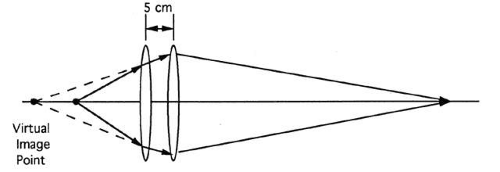 Fig. 37. The first lens creates a virtual image that becomes the object point for the second lens, which has enough power to converge the rays and form a real image. |
No light goes through this virtual image point. Light does not travel over the part of the image rays extended backward. The virtual image point is a mathematical construct; if a piece of paper is placed 20 cm in front of the first lens, no image will be observed. This mathematical construct is called virtual because it does not represent a real image. It is called an image because it is associated with the image rays emerging from the first lens.
The virtual image is 25 cm in front of the second lens. Thus, light incident on the second lens has a vergence of -4.00 D. Light emerging from the second lens has a vergence of + 2.00 D, giving an image 50 cm behind the second lens.
Next, consider an object far away from a + 2.00 D lens. The lens forms an image 50 cm behind itself. Where is the image if a + 6.00 D lens is placed 25 cm behind the first lens (Fig. 38) Again, the vergence of the light incident on the second lens is the key issue. Light incident on a lens from a real object is always divergent. However, in this case, the light incident on the second lens is convergent. The convergent light is associated with an object point 50 cm behind the lens, but real objects are always in front of a lens. This example represents a virtual object. The virtual object is 25 cm behind the second lens, giving the incident light a vergence of + 4.00 D. Rays emerging from the second lens have a vergence of + 10.00 D, giving an image 10 cm behind the second lens.
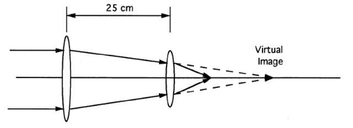 Fig. 38. The first lens creates a virtual image that becomes the object for the second lens. |
It is often incorrectly stated that real images are always inverted and virtual images are erect. There is no inherent relationship between an image’s orientation and its status as real or virtual. An image is real if the image rays are convergent, and virtual if the image rays are divergent. An object is real if the object rays are divergent, and virtual if the object rays are convergent.
An important difference between the examples in this section and those of previous sections is that these cases involve more than one element. Virtual images and objects are primarily mathematical tools (but very useful ones) for dealing with multiple lenses.
REFRACTIVE INDEX
A medium is anything that light can travel through, such as glass, liquids, air, a vacuum, and even some metals. The speed of light varies in each medium. Light travels fastest in a vacuum and slower in any material medium.
Rather than deal directly with light’s speed in a medium, it is usually more convenient to use refractive index. The refractive index of a medium is the ratio of light’s speed in the vacuum to its speed in the medium. For example, the refractive index of spectacle crown glass is 1.523, indicating that light’s speed in glass is about two-thirds its speed in a vacuum. Refractive index is always a number greater than or equal to 1. It is routine practice to use the lowercase letter “n” to indicate refractive index in formulas and equations.
Refractive index varies with wavelength. In general, the shorter the wavelength, the higher the refractive index. For instance, in spectacle crown glass, light of wavelength 656 nm (corresponding to red) has an index of 1.520, whereas light of wavelength 480 nm (corresponding to blue) has an index of 1.531. Dispersion is the variation of refractive index with wavelength. In the crown glass example, the dispersion is 0.011 (= 1.531 – 1.520). Each medium exhibits a different amount of dispersion, and not all media are dispersive. All wavelengths travel the same speed in a vacuum. The dispersion of air is so small that it can be ignored.
Refractive index is quite sensitive to chemical composition. It is easy to measure the refractive index difference between distilled water and physiologic saline. In the past, glycosuria was diagnosed by measuring urine refractive index. Manufacturers alter the optical properties of glass by adding small amounts of rare earth elements such as barium. Over 200 different types of optical glass with different indices (and dispersions) are commercially available.
Environmental factors such as temperature and atmospheric pressure can also influence refractive index, but the effects are usually small enough to be ignored. A notable exception is the index of silicone (20°C), which is strongly temperature dependent. Manufacturers should measure the power of silicone intraocular lenses at (or adjusted for) eye temperature (35°C) rather than at room temperature, or a clinically significant error in power may occur. Humidity can affect the refractive index of soft contact lenses by altering the water content.
FERMAT’S PRINCIPLE, REFRACTION, AND REFLECTION
Optical systems produce images by redirecting light. Fermat’s principle governs the movement of light through an optical system. According to Fermat’s principle, natural processes occur in extreme ways. Applied to light, Fermat’s principle states that light travels from point A to point B along the path requiring the least time.
For instance, suppose light moves from A to B by reflection from a flat mirror. Figure 39 shows various potential pathways that light could follow. One path is shorter than any other; therefore, light moving along this path reaches B in the least time. Light moves from A to B only along this path. Of course, A is a point source and gives off light in all directions. Other rays from A reflect in different directions and do not reach B (Fig. 40).
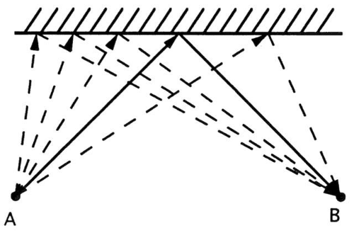 Fig. 39. Light travels from point A to point B by reflection from the plane mirror. Several hypothetical paths are shown. Light travels only along the shortest path (least time). |
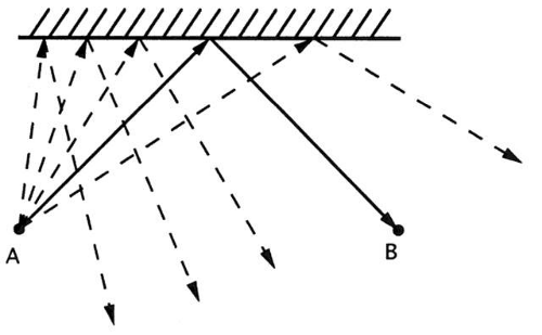 Fig. 40. In reality, only one ray from A travels along the shortest path to B. The other rays follow different directions. |
It is possible to show mathematically that for the shortest path the incident and reflected rays are always symmetric. Thus, the law of (specular) reflection follows from Fermat’s principle. To state the law of reflection formally, it is necessary to define some additional terms. The surface normal is an imaginary line perpendicular to a surface at the point where a ray strikes the surface. There is a different surface normal at every point on a surface. The angle of incidence is the angle between the surface normal and the incident ray. The angle of reflection is the angle between the surface normal and the reflected ray. The law of reflection states that the incident ray, reflected ray, and surface normal lie in the same plane, and the angles of incidence and reflection are equal.
A flat mirror reflects a single ray from A to B. To produce a stigmatic image of A at B, all rays striking the mirror must pass through B. By Fermat’s principle, this can happen only if every path from A to B has the same length. Bending the mirror equalizes the path lengths. In this case, an elliptical mirror gives a stigmatic focus (Fig. 41). The mirror’s shape must be perfect, and it is not easy to fabricate such a mirror. If the shape is slightly off, some reflected rays will miss B but pass nearby.
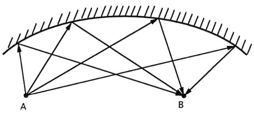 Fig. 41. By bending the mirror, all paths from A to B can be made equal in length. The mirror now gives a stigmatic image (of point A) at B.
Stay updated, free articles. Join our Telegram channel
Full access? Get Clinical Tree
 Get Clinical Tree app for offline access

|