Evaluation of the Posterior Chamber, Vitreous, and Retina with Ultrasound
D. Jackson Coleman
Ronald H. Silverman
Harriet O. Lloyd
Suzanne Daly
Ultrasound is an essential tool for evaluation of the posterior segment of the eye, allowing identification and characterization of vitreous hemorrhage or inflammation, retinal or choroidal detachment, tumors, foreign bodies, and ocular wall shape and thickness, even in the presence of intervening optical opacities. In addition, ultrasound offers a real-time exam and can thus provide information on the mobility of vitreous membranes, detached retina, and hemorrhage through kinetic examination procedures.
PHYSICS AND TECHNOLOGY
Advances in instrumentation, higher frequencies, and improving sensitivity and resolution have resulted in continuous improvement in ultrasound image quality.1 As with any imaging technique, familiarity with the principles and physics of the methodology is necessary in order to properly recognize the advantages as well as limitations of the technique in a given clinical setting and to minimize difficulties in interpretation of the image.
The physical basis of ultrasound imaging is the partial reflection of ultrasound when the acoustic pulse emitted by the transducer encounters tissue structures differing in acoustic impedance (density × speed-of-sound) relative to the surrounding tissue media, as it propagates through the tissue. Since echo amplitude is proportional to relative impedance, ultrasound images do not depict density, as would an x-ray, but rather density variation (or more precisely, acoustic impedance variation). The range to any echo is determined by measuring the time-of-flight between emission of an acoustic pulse by the transducer and echo return and applying an appropriate speed-of-sound constant, typically 1,532 m/s. Two-dimensional B-mode images are formed by sweeping the transducer over an angle of about 50° while recording echo data along numerous lines-of-sight and setting pixel intensity proportional to echo amplitude (or sometimes the logarithm of amplitude) and mapping the range and angle orientation to each echo to image display position.
The resolution obtainable by ultrasound is proportional to wavelength, which is approximately 150 µm at 10 MHz, the frequency most widely used for imaging the eye. More precisely, resolution is proportional to the duration of the ultrasound pulse emitted by the transducer. Thus, even a high-frequency transducer might produce poor resolution if the emitted pulse is insufficiently damped, that is, is many cycles in duration. As frequency increases, wavelength gets shorter and achievable resolution improves. Like light, ultrasound is subject to the laws of reflection and refraction. Smooth tissue surfaces such as the cornea, lens, and the walls of cysts may produce bright specular reflections. Solid tissues such as orbital fat and tumors may produce an echo texture known as “speckle” that results from summation of echoes from sub-resolvable tissue inhomogeneities.
While the two-dimensional gray-scale B-scan is the primary display mode for ultrasound diagnostic imaging, ophthalmic ultrasonography remains one of the few clinical specialties where A-scan, a plot of echo amplitude as a function of range, continues to be used for biometry and to differentiate tissue characteristics. Although improved B-scan gray scale has diminished some of the advantages of A-scan, A-scan is still necessary for quantifying echo amplitudes, particularly when distinguishing vitreous membranes from retina or identifying tumor types2 and continues to play a major role in axial length determination and corneal pachymetry.
In general, ophthalmic diagnostic ultrasound systems use focused, single-element 10 to 12 MHz mechanical sector scan probes to provide the best quality two-dimensional B-scan image of the eye and orbit.2 In contrast, linear arrays are the dominant ultrasound technology in other clinical specialties. Such systems offer advantages over mechanically scanned single-element probes, including synthetic focusing, high frame rate, and color-flow Doppler imaging, to name a few. Array-based systems have not penetrated ophthalmology for several reasons; among them are lack of arrays with frequencies sufficiently high for ophthalmic applications, lack of ophthalmic 510(k) FDA certification by manufacturers, and cost. These factors are gradually being addressed, and it is probable that these systems may become available for ophthalmic examination in the near future.
An intermediate strategy has been the development of prototype annular arrays, comprised of a series of concentric rings or annuli, that can independently emit and receive echoes.3 Annular array are advantageous compared to conventional single-element transducers by providing synthetic focusing, greatly extending depth-of-field. They are also advantageous compared to linear arrays in terms of simplicity (a typical annular array may have only 5 elements, compared to a linear array with typically over 100 elements) and a radial symmetric beam profile, which improves resolution, although, like single-element transducers, they must be mechanically scanned to form B-mode images.3,4
Ultrasound biomicroscopy (UBM), or very high-frequency ultrasound (VHF) systems use frequencies in the range of 35 to 50 MHz. The wavelength at 50 MHz is 30 µm, allowing resolution of much finer features than can be obtained at 10 MHz. Foster and Pavlin developed the first practical UBM system for imaging of the eye.5,6 The Ultrasound Biomicroscope (Zeiss-Humphrey Instruments, San Leandro, California) was a commercial outgrowth of this work, allowing widespread clinical application. UBM systems are now available from many ophthalmic ultrasound manufacturers. With UBM, penetration is limited to only 5 to 10 mm, and thus only the anterior vitreous behind the ciliary body and lens can be imaged. However, UBM represents an invaluable tool for anterior segment evaluation and assessment of conditions such as trauma, glaucoma, hypotony, and other conditions that may require vitrectomy or surgical intervention.
Although the vitreous, like water, has a low ultrasound attenuation coefficient, attenuation even by the vitreous at UBM frequencies is too high to allow examination of the retina in this frequency range. Frequencies as high as 20 to 25 MHz, however, may be used for evaluation of the retina, choroid, and optic nerve head.7,8 20 megahertz probes have become commercially available on some ophthalmic ultrasound instruments.
Optical coherence tomography (OCT) offers invaluable information in the management of pathologies affecting the retina, choroid, and optic nerve. The first OCT images of the eye were described by Huang et al. in 1990.9 OCT is sometimes referred to as an optical analog of ultrasound, as images are formed by scanning a low-coherence light beam and the signal is a result of reflection and scattering of light by inhomogeneities in optical refractive index, which, like acoustic impedance, is related to density. While OCT images have a similar qualitative appearance to ultrasound images, OCT provides an order of magnitude improvement over ultrasound in terms of resolution and imaging speed, and these characteristics have made it the method of choice for evaluation of the retina. Until recently, OCT systems could not penetrate beyond the retinal pigment epithelium, but improvements in sensitivity conferred by spectral-domain10 and swept-source11 modalities now allow evaluation of the choroid. In the anterior segment, OCT can provide excellent images of the cornea and anterior chamber, including the iridocorneal angle.12,13,14 Absorption and scattering of light by the sclera and iris, however, result in poor visualization of retroiridal structures and the ciliary body. While OCT can visualize vitreous membranes, this is mostly limited to the perimacular area due to the limited depth-of-field and inaccessibility of the anterior vitreous to optical examination. The presence of pathologic optical opacities (corneal scar, cataract, hemorrhage) will limit the utility of OCT. Thus, while OCT is a superb tool, ultrasound continues to play a major role in evaluation of retroiridal structures, the anterior and peripheral vitreous, tumors, and the orbit and the retina where optical opacities are present.
IRIS, CILIARY BODY, ANTERIOR VITREOUS, AND LENS
Iris swelling or pigmentation, trauma, foreign body, hypotony, complications of cataract surgery, IOL dislocation, or suspected ciliary body tumors are all indicators for high-frequency ultrasound evaluation.
UBM provides excellent resolution for assessment of the lens and lens implants, but may at times lack sufficient penetration to adequately view the posterior lens capsule. Utilization of lower frequency probes, especially in combination with UBM, in such instances can therefore be advantageous.15 With sector B-scan probes, the concave geometry of the posterior capsule presents perpendicular to the ultrasound beam, thus making it always easy to identify. In a contact exam, however, the anterior segment is in the unfocussed near field, and the lens, especially its convex anterior surface, are poorly visualized. Immersion with a normal saline standoff makes it possible to better visualize the anterior segment by placing the structures of interest in the focal zone of the transducer. Immersion setups may be performed by creating a water bath around the eye with a steridrape, with a central aperture adhering to the skin around the eye and supported by a ring stand or by a scleral shell. More recently, disposable ClearScan (ESI, Inc., Plymouth, Minnesota) probe covers that are water-filled bubble tips have been introduced for this purpose.
Specular reflectors such as the lens deflect most acoustic energy away from the transducer when insonified at an oblique angle. However, if blood is present, it may enhance lens boundaries by converting the normally specular surface to a diffusely reflective surface. The normal lens outline should be smooth and unbroken as shown at 40 MHz in Figure 3.1; a cataractous lens (Fig. 3.2) or damaged (Fig. 3.3) lens often has internal echoes as well as interrupted surface echoes.16 Kinetic scanning, that is, real-time scanning while the patient moves his or her eye, can be used to check for mobility of the lens in dislocated or partially dislocated lenses. Modern digital ultrasound systems allow acquisition of “cineloops” to record kinetic exams. Intraocular lens displacement, particularly erosion of haptics that may produce bleeding, is a commonly seen problem. An example of a normal posterior chamber intraocular lens implant is seen in Figure 3.4, and a displaced lens implant and haptic, following blunt trauma is shown in Figure 3.5.
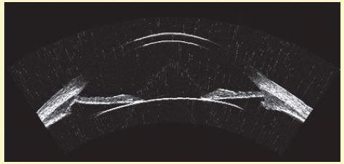 FIG. 3.1 40 megahertz image of normal anterior segment of 31-year-old female subject acquired by arc-scan. (See Fig. 3.26 for improved outline by use of compound scans.) |
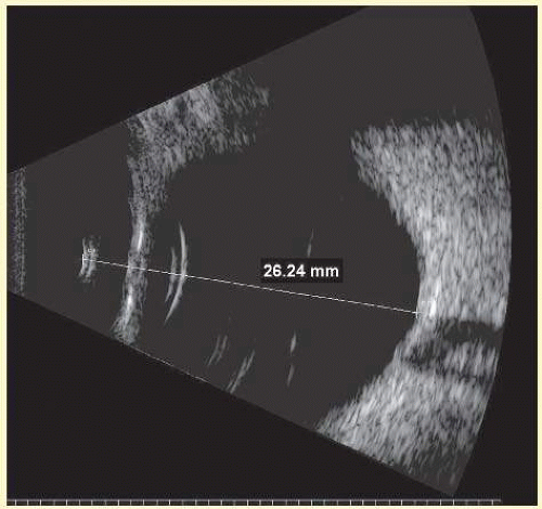 FIG. 3.2 Immersion 10 MHz sector B-scan of myope with cataractous lens. Axial length determinations by immersion B-scan can be particularly useful in high-myopes, staphylomatous eyes, and in presence of dense cataract. Double echo at posterior lens surface is due to cataract. |
The four main areas of interest in the posterior chamber to the ocular surgeon are: (1) iris and ciliary body tumors, (2) intraocular foreign bodies and trauma that may involve the lens, (3) intraocular lens placement and position that may cause irritation or decreased vision and (4) hypotony with separation of the ciliary body from the sclera.17,18,19 Examples of a retroiridal cyst and a tumor are shown in Figures 3.6 and 3.7, respectively.
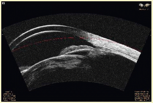 FIG. 3.3 UBM image of cataract in 64-year-old female, 3 months following blunt trauma. Suggestion of possible iridodialysis at angle. |
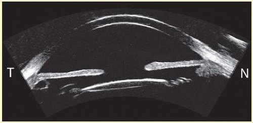 FIG. 3.4 UBM image in horizontal plane of anterior segment of right eye with intraocular lens implant. Note small, asymptomatic retroiridal cyst temporally. |
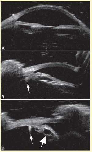 FIG. 3.5 UBM images of anterior segment of 70-year-old man, 6 days after traumatic displacement of lens implant. A: The lens is less reflective than normal in a horizontal axial view because it is tilted in the out-of-plane axis. B shows the appearance in the vertical plane, where the lens is obviously displaced inferiorly. C: The inferior aspect of the anterior segment is visualized in a vertical plane and the haptic (small arrow B and C) is seen to be displaced inferiorly almost to the pars plana. Note the retroiridal cyst (large arrow). |
Hypotony is easily diagnosed by direct measurement of intraocular pressure, but the underlying cause may be difficult to evaluate.17 High-frequency ultrasound scans can easily reveal separation of the ciliary body and the sclera. This allows different forms of hypotony to be determined, for example, tractional with membrane attached, primary as idiopathic, often inflammatory or hemorrhagic, and dehiscence secondary to iridodialysis or scleral perforation. An example of a UBM in a case of posttraumatic hypotony is shown in Figure 3.8.
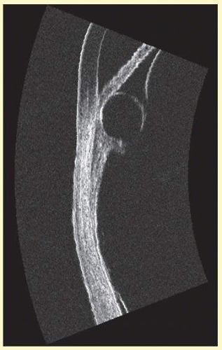 FIG. 3.6 High-frequency image of large retroiridal cyst in right eye of female subject. |
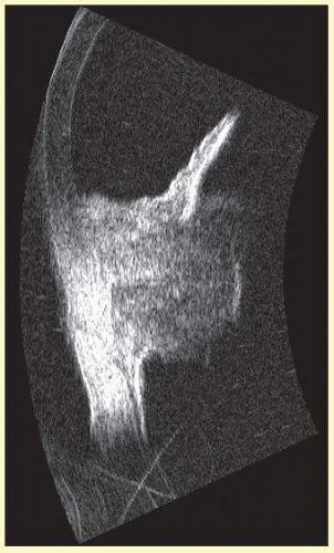 FIG. 3.7 High-frequency image of malignant melanoma involving the iris and ciliary body in the right eye of a 61-year-old female. UBM is particularly useful in imaging pigmented lesions that are seen near the angle to determine involvement of the ciliary body. |
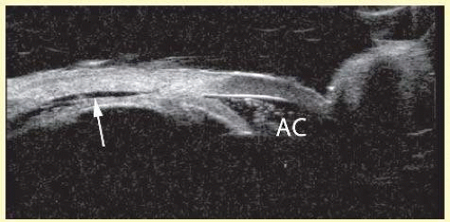 FIG. 3.8 UBM image of the nasal aspect of the anterior segment of the left eye of a 28-year-old male following blunt trauma. The ciliary body was detached (arrow) over 360°. Note hemorrhagic debris in anterior chamber (AC). |
THE VITREOUS
The young, healthy vitreous is a homogeneous, optically transparent gel, filling the posterior segment of the eye. Liquid vitreous appears by the age of 4 and increases throughout life until it constitutes more than half of the volume of the vitreous by the eighth decade.20 Oksala demonstrated age-related changes in the vitreous body with 6-MHz A-scan ultrasound in 1978.21 Such ultrasonically detectable changes are caused by fluid-gel interfaces. These interfaces produce echoes that are readily detectable by B-scan at high gain settings and are typically mobile on kinetic examination (Fig. 3.9). The process of vitreous liquefaction may result in separation of the formed vitreous from the retina, or posterior vitreous detachment (Fig. 3.10).22
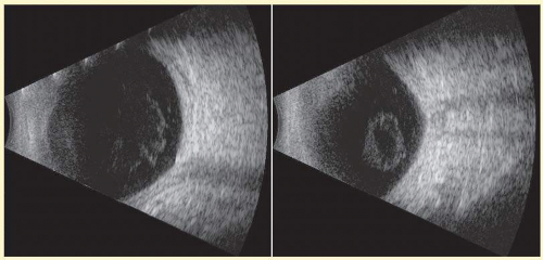 FIG. 3.9 Two views of left eye of 76-year-old female patient obtained in a contact 10 MHz exam. Note presence of vitreous inhomogeneities whose shape varies on kinetic exam. |
Fresh blood in the vitreous may be acoustically clear since the red cells may not have congealed sufficiently to form an echo-producing mass.23 Figure 3.11 shows an example of a fresh hemorrhage in the vitreous and anterior chamber. A retracted “hyaloid” or posterior limiting membrane (PLM) of the vitreous can be shown with most B-scan instruments, but, paradoxically, a retracted vitreous may not be seen as well with higher resolution, more highly focused transducers since they display less area of the reflective surface. Blood collected on the surface of the PLM enhances this surface and may, in some cases, make the PLM resemble a detached retina, since its anatomic dimensions can be similar to the retina. Three differences may help distinguish the two structures. First, kinetic scanning reveals a lack of attachment at the optic nerve for a PLM. Second, the PLM is irregular in reflection and thickness (usually thicker than the retina) between the ora and the disc, and usually the surface cannot be traced forward to the ora on the B-scan display. Third, the amplitude of the echoes from the PLM is lower than the retina except when directly perpendicular to the beam, where they may be similar in amplitude.
Asteroid hyalosis (Fig. 3.12) can resemble a vitreous hemorrhage except that the individual calcium deposits are even more reflective than hemorrhage, and, usually, there is a clear anechoic zone between the retina and the retracted primary vitreous. Synchysis scintillans is another condition with highly reflective regions in the vitreous due to cholesterol crystals and is identifiable by the kinetic scan pattern of floating “snowflakes” that settle when the eye stops moving, just like the snowflakes in a child’s snow globe. Since the “normal” vitreous is usually dissolved in this condition, the echoes come to rest on the retinal surface when the eye stops moving.
Stay updated, free articles. Join our Telegram channel

Full access? Get Clinical Tree


