. On the contrary, the relative bandwidth Δλ/λ provides a more convenient and natural bandwidth measure because it does not depend on the central wavelength, it is the same in wavelength and frequency domains, and it is directly connected to the number of cycles per pulse (Δλ/λ)−1 ≈ (Δν/ν)−1 α N.
Ions belonging to one of the series of transition elements of the Periodic Table, in particular rare earth (RE) or transition-metal (TE) ions, are generally used as the active impurities in lasers. These active ions are embedded in either oxides, e.g., Al2O3, or fluorides, e.g., YLiF4. The Al3+ site is too small to accommodate RE ions, so it is generally used for transition-metal ions, while the Y3+ site can be used for RE ions. Also, LiSrAlF6 (LiSAF) or LiCaAlF6 (LiCAF) are used for transition metals – most common for Cr3+ ions. Oxides are very hard and offer good mechanical and thermomechanical properties. In contrast, fluorides are soft, but also have good thermo-optical properties (i.e., low thermal-induced birefringence and lensing). Glasses have a low melting temperature, so they can be produced very cheap, but they have a low thermal conductivity, thus bad thermomechanical and thermo-optical properties. We will only review transition-metal-doped materials, since rare earth-doped materials offer bandwidths and wavelengths that have not typically been used for OCT.
19.1.1 Transition-Metal-Doped Materials
The electronic configuration of Cr can be written as (Ar)3d54s1, while those of Ti, Co, and Ni can be written in the general form (Ar)3dN4s2 (with N = 2 for Ti, 7 for Co, and 8 for Ni). By adding a chromium atom to an ionic crystal, the one electron belonging to its 4 s orbital and two 3d electrons are used for ionic binding, and Cr is found as a triply ionized ion with three electrons left in the 3d shell. In titanium, the two 4s electrons and one 3d electron are used for ionic binding, and Ti is again present as a triply ionized ion with only one electron left in the 3d shell. All absorption and emission features of transition-metal ions arise from 3d-3d transitions. The 3d states interact strongly with the crystal field of the host leading to the vibronic character of the corresponding transitions and to ultrabroad absorption and emission bands. Electric-dipole transitions within the 3d shell are parity forbidden. The crystal field is much stronger than in RE materials. As a result, the 3d-3d transitions are more readily allowed, and the lifetimes are significantly shorter (a few microseconds) than those of the 4f-4f transitions in RE ions. Doping of crystals or glasses with transition-metal ions supports a strong coupling of the electronic levels of the doped laser ion to the phonon relaxations of the host lattice leading to a good separation of absorption and emission spectra.
19.1.1.1 Ti:Sapphire
Since the reporting of laser action by Moulton in 1982 [3], the Ti:sapphire laser has been the subject of intensive investigations and has become the most widely used tunable solid-state laser and the medium of choice for ultrafast pulse generation because of the broad amplification bandwidth. Ti:sapphire systems provide a tuning range of about 400 nm (corresponding to Δν 0 ≈ 100 THz) with a relatively large gain cross section centered at 800 nm, thus providing the largest bandwidth of any lasers shown to date. This large optical bandwidth has made Ti:Sapphire a medium of choice for UHR OCT in the NIR regime.
19.1.1.2 Alternative Solid-State Light Sources
Cr3+:LiSAF and Cr3+:LiCAF offer a wide tuning range, and the corresponding lasers can be either flash lamp pumped or diode-laser pumped. In both systems, Cr3+ ions replace some of the Al3+ ions in the lattice, and the impurity ion occupies the center of a (distorted) octahedral site surrounded by six fluorine ions. Due to its wider tuning range and higher n2, Cr:LiSAF is generally preferred to Cr:LiCAF. Due to the large gain linewidth centered around 850 nm and the possibility of diode pumping with laser diodes at 670 nm wavelength, these media are also attractive for generating femtosecond pulses. Sub-10 fs pulses from diode-pumped Kerr-lens mode Cr-doped colquirite laser have been reported [4, 5], making these systems competitive with Ti:sapphire lasers in terms of performance. Other interesting broadband lasing materials include Cr:LiSGaF in the 800 nm regime, Cr4+:MgSiO2 in the 1,350 nm regime, and Cr4+:YAG in the 1,500 nm regime. Interesting lasing materials in the infrared are Cr2+:ZnSe operating at 2.5 μm or Co2+:MgF2 centered at 2 μm. Table 19.1 compares the optical properties of these gain media.
Table 19.1
Optical properties of broadband laser materials
Material | Pump band λ (μm) | Emission cross-section σ (10–19 cm2) | Upper state lifetime τ (μs) | Absorption band λ (μm) |
|---|---|---|---|---|
Ti3+:sapphire | 0.45–0.6 | 3.8 | 3.2 | 0.6–1.05 |
Cr3+:LiSGaF | 0.60–0.7 | 0.33 | 88 | 0.7–1.05 |
Cr4+:forsterite | 0.85–1.2 | 1.1 | 15 | 1.1–1.37 |
Cr4+:YAG | 0.88–1.1 | 8 | 4 | 1.35–1.65 |
19.1.2 Femtosecond Lasers
Ultrashort light pulses represent the shortest, controlled, and technically produced events. To put the time scale of the femtosecond pulse in context, consider that one femtosecond compared to a second is equivalent to 5 min compared to the age of the universe. Such short laser pulses are very attractive for two reasons: they concentrate a large amount of energy within a short time interval and offer a broad bandwidth coherent pulse spectrum. Femtosecond laser development to date has mainly concentrated on the temporal features of the pulses, which were often optimized to the detriment of the spectral shape. In OCT imaging, however, the spectral width and shape rather than the pulse duration is most important. Since shorter pulse width corresponds to broader spectrum, short pulses and broadband spectrum cannot be regarded as independent. They are connected via a time/frequency uncertainty relationship (time-bandwidth product). Short pulse duration allows for time-resolved studies of fast processes occurring on a time scale of the pulse width, while applications like OCT benefit from the broad coherent pulse spectrum.
However, unlike ultrafast femtosecond time-resolved measurements where special care must be exercised to maintain the short pulse duration, OCT measurements depend on field correlations rather than intensity correlations. Field correlation is preserved even if the pulse duration is long. Femtosecond mode-locked solid-state lasers can generate ultrabroad bandwidth, low-coherence light with a single spatial mode and high power, providing both high resolution and high brightness necessary for high-speed OCT imaging. These lasers can operate over a broad range of wavelengths that are desirable for ultrahigh-resolution as well as spectroscopic OCT imaging in tissue. Since the early days of OCT Ti:sapphire lasers have widely been used for in vitro and in vivo OCT imaging in nontransparent tissues [6].
19.1.3 Mode Locking
The ability to deliver high brightness, broadband light from solid-state lasers for OCT imaging is, in turn, intimately linked to the ability to generate ultrashort optical pulses through mode-locking techniques. In a free-running laser, typically a large number of transverse and longitudinal modes are oscillating simultaneously without fixed mode-to-mode amplitude and phase relationships. The resulting laser output is a time-averaged statistical mean value. The formation of a mode-locked pulse train from noise starts with the selection of one peak fluctuation or at least a small number. By forcing the longitudinal modes to oscillate with some definite relation between their phases, the modes interfere and produce short pulses in the pico- or femtosecond regime which is referred to as mode-locked. In this case, very short pulses with high intensities can be generated, especially when the phase offset between different frequencies approaches zero. In the frequency domain, mode-locking corresponds to a frequency comb of equally spaced synchronized modes. A short pulse corresponds to a broad frequency comb. In the time domain, it corresponds to a light pulse traveling inside the laser cavity.
A large number of mode-locking techniques have been developed to generate short pulses in solid-state lasers:
Active mode-locking – the longitudinal modes are locked by a phase or frequency modulator driven by an external source. An RF signal is applied to the modulator at exactly the frequency interval of the longitudinal modes.
Passive mode-locking – the longitudinal modes are locked by an element that is not driven externally but instead exploits some nonlinear optical effect, such as saturation of a saturable absorber or a nonlinear refractive index change in a suitable material.
Nowadays, Kerr-lens mode-locking is the state-of-the-art method for sub-10 fs pulse generation directly from a mode-locked laser. In Kerr-lens mode-locking [7], strong nonlinear refraction at high peak intensities causes self-focusing of Gaussian beams. Since it relies on a nonresonant electronic nonlinearity, its response time is less than a femtosecond. The fast self-amplitude modulation of the pulses due to the Kerr effect can shape and stabilize extremely short pulses. The pulse propagates with the group velocity which can be expressed by

where β″ is the group dispersion of the medium. Materials in the visible region of the spectrum have positive or normal dispersion, i.e., β″ > 0. Therefore in a laser crystal, v g decreases with increasing frequency. Longer wavelengths travel faster than shorter ones, causing a redshift of the pulse. High-intensity mode-locked pulses are redshifted due to self-phase modulation and normal dispersion. Positive self-phase modulation and positive group-velocity dispersion in the Kerr medium can be compensated for by a dispersive delay line based on prism pairs introducing negative dispersion into the resonator. Although the glasses of the prisms have normal dispersion, the geometry of the ray path can be arranged such that the blue components of the pulse pass the prisms in a shorter time than the red components. Although a number of prism arrangements can be devised, usually two prisms are used at minimum deviation and Brewster’s angle incidence at each surface. Also dispersive (chirped) mirrors are widely used for dispersion compensation.
(19.1)
Since the Kerr nonlinearity is usually not strong enough for the cw mode-locking process to self-start, usually a strong fluctuation must be induced by either perturbing the cavity or by adding nonlinearity to the system (saturable absorber). The simplest method to start KLM in a laboratory setup is to slightly tap one of the resonator mirrors. Disturbing the cavity mirrors will sweep the frequencies of competing longitudinal modes, and strong amplitude modulation due to mode beating will occur. The most intense mode-beating pulse will be strong enough to initiate mode locking.
19.1.4 Resonator Design
A resonator commonly employed for KLM is an astigmatically compensated cavity consisting of a pair of focusing mirrors and one or two flat mirrors. The laser crystal as a Kerr medium is inserted into a tightly focused section of the resonator for high nonlinearity. KLM can be established as a trade-off between output power, stability, and tolerance to the exact position of the components. An analytical treatment of nonlinear resonators has shown that for a given pump power and pump spot size, the most critical parameters are the distance of the two focusing mirrors and the location of the Kerr medium with respect to the mirrors [8].
In a basic oscillator-cavity configuration, the laser is pumped from a continuous-wave (cw) laser source, which is usually now an intracavity-doubled diode-pumped neodymium laser. Recently also compact frequency-doubled DBR-tapered diode lasers for direct pumping of Ti:sapphire lasers have been demonstrated [63]. This pump light is focused into a Brewster’s angle cut crystal, collinearly with the laser axis, through the back side of one of the focusing mirrors and the fluorescent light (laser light) bounces between two concave focusing mirrors placed around it, several dispersive mirrors, and an output coupler. High doping concentration and reasonable lengths of laser crystals are necessary for efficient absorption of the pump radiation.
19.1.4.1 Cavity Dispersion in Femtosecond Mode-Locked Lasers
In the generation of ultrashort pulses, a key limitation poses the linear dispersion within the laser material itself, which causes a wavelength-dependant delay: long-wavelength components of the pulse spectrum propagate faster than the short-wavelength components.
For this reason, the concepts of phase velocity, group velocity, and group delay dispersion in a dispersive medium have to be reviewed.
The electric field E(t,z) of a plane, linearly polarized, monochromatic electromagnetic wave traveling at a frequency ω in the z-direction in a transparent medium can be written as
with A 0 as a constant and β as the propagation constant which is a function of the angular frequency ω. In this case, the propagation constant β = β(ω) is a characteristic of the given medium, referred to as the dispersion relation of the medium. The total phase of the wave is now ϕ t = ωt − βz. Elemental changes dt and dz of the temporal and spatial coordinates of the velocity of a given phase front must fulfill the condition dϕ t = ωdt − βdz = 0 giving

where v ph is the phase velocity of the wave.
(19.2)
(19.3)
Since a light pulse is generally traveling in the medium and ω L is the center frequency and Δω L the width of the corresponding spectrum, the dispersion relation over the bandwidth Δω L can be approximated by a linear law
with β L as propagation constant corresponding to the frequency ω L , where the electric field can be expressed as
![$$ E\left(t,z\right)=A\left[t-\left(z/{v}_g\right)\right] \exp \left[j\left({\omega}_Lt-{\beta}_Lz\right)\right] $$](/wp-content/uploads/2017/03/A76297_2_En_20_Chapter_Equ5.gif)
and A is the pulse amplitude, exp[j(ω L t − β L z)] is the carrier wave, and ν g is the group velocity given by
(19.4)
(19.5)
(19.6)
Due to the fact that the pulse amplitude is a function of the variable t–(z/v g ), the pulse propagates at a speed v g without changing its shape. After traversing the length l of the medium, the pulse experiences a time delay
where the phase ϕ is dependent on the frequency ω
and
![$$ {\phi}^{\prime}\left({\omega}_L\right)={\left[d\phi \left(\omega -{\omega}_L\right)/d\omega \right]}_{\omega_L} $$](/wp-content/uploads/2017/03/A76297_2_En_20_Chapter_Equ9.gif)
is referred to as the group delay of the medium at the frequency ω L
(19.7)
(19.8)
(19.9)
When two pulses with bandwidths Δω 1 and Δω 2 centered at ω 1 and ω 2 travel in the medium (ω 2 > ω 1), the two pulses travel at different group velocities v g1 and v g2. Thus, if the peaks of the two pulses enter the medium at the same time, then, after traversing the length l of the medium, they become separated in time by a delay
with
![$$ {\phi}^{{\prime\prime}}\left({\omega}_1\right)={\left[{d}^2\phi /d{\omega}^2\right]}_{\omega_1} $$](/wp-content/uploads/2017/03/A76297_2_En_20_Chapter_Equ11.gif)
(19.10)
(19.11)
Light pulses with large bandwidths Δω L cannot any longer be described by the linear dispersion relation. Different spectral regions of the pulse travel with different group velocities resulting in a pulse broadening. Assuming that the dispersion relation within the bandwidth Δω L can be approximated by a parabolic law, the pulse broadening due to dispersion Δτ d is given approximately by the difference in group delay between the fastest spectral component and the slowest one
(19.12)
The quantity ϕ″(ω L ) is referred to as the group delay dispersion (GDD) of the medium at frequency ω L and is a measure for the pulse broadening per unit bandwidth of the pulse. It can also be written as
where the quantity group-velocity dispersion (GVD) at frequency ω L is given
![$$ GVD={\left(\frac{d^2\beta }{d{\omega}^2}\right)}_{\omega {}_L}={\left[\frac{d\left(1/{v}_g\right)}{d\omega}\right]}_{\omega_L} $$](/wp-content/uploads/2017/03/A76297_2_En_20_Chapter_Equ14.gif)
(19.13)
(19.14)
Its magnitude gives the pulse broadening per unit length of the medium and per unit bandwidth of the pulse. This concept for the GVD can only be applied for homogeneous media. For an inhomogeneous or multicomponent medium, GDD is differently to consider.
19.1.4.2 Introducing Negative Dispersion into the Laser Cavity: Dispersion Management
Since the laser crystal provides positive or normal dispersion, a suitable element providing negative or anomalous dispersion is required for the compensation of the cavity GDD. Advances in crystal growth have allowed for thinner and thinner crystals with higher doping levels, but crystals ∼2 mm thick are still required to achieve a reasonable gain. Compensation of the crystal’s positive group delay dispersion with the opposite negative group delay dispersion introduced by an intracavity prism pair [9] ultimately led to fourth-order dispersion limited pulses of sub-10 fs duration.
A four-prism sequence allows for accurate dispersion compensation and low losses since all surfaces are at Brewster’s angle to the beam path so that the GDD of the laser rod can be compensated for. The negative value of GDD can be coarsely changed by changing the separation l of the two prism pairs. By translating any one of the prisms along an axis normal to its base, the total length of the optical medium traversed by the beam can be changed. This motion introduces, in a finely controlled way, a positive (material) dispersion of adjustable size without altering the ray directions and hence the negative dispersion due to the geometry of the ray path. Since the transmitted beam is collinear with the incident beam, this facilitates inserting the four-prism sequence in an already aligned cavity. One of the drawbacks is that not only second-order dispersion but also third-order dispersion is introduced (fused quartz is one of the best optical materials with a very low ϕ‴/ϕ″ ratio). Simultaneous third-order dispersion (TOD) compensation is possible only at specific wavelengths depending on the rod and prism material. Therefore, limitations are due to the insufficient cancellation of higher-order dispersion terms (third, fourth, etc.) resulting in pulse duration of about 10 fs in Ti:sapphire oscillators. For Ti:sapphire lasers, simultaneous GDD and TOD compensation can be achieved in wavelengths ranges of a few nanometers around 800 nm with beryllium oxide (BeO) prisms, around 850 nm with fused silica and around 880 nm with BK7. Using solely fused silica prisms for the dispersion compensation, sub-10 fs pulses were reported for the first time directly from an oscillator [10]. These pulses showed M-shaped spectra owing to the fourth-order dispersion that was found to limit the achievable bandwidth. There exist compensation schemes with only one or more than two intracavity prisms, but none seems to allow for the intracavity dispersion compensation required for pulse durations below 8 fs. For even shorter pulse generation in the regime of one optical cycle, the development of dispersive high-reflective broad bandwidth mirrors is mandatory. Szipöcs [11, 12] set a new milestone in ultrashort pulse generation with the invention of chirped mirrors (CM). These first CM designs were obtained by computer optimization of “chirped” Bragg reflectors (cf. Fig. 19.1). Szipöcs reported a design consisting of 42 alternating layers of SiO2 and TiO2, which had a bandwidth of 200 nm at a center wavelength of 800 nm. Other than the geometric dispersion approaches, they allow for compensation of arbitrary higher-order dispersion. Several advances in laser technology with chirped and double-chirped mirrors have resulted in octave-spanning spectra.
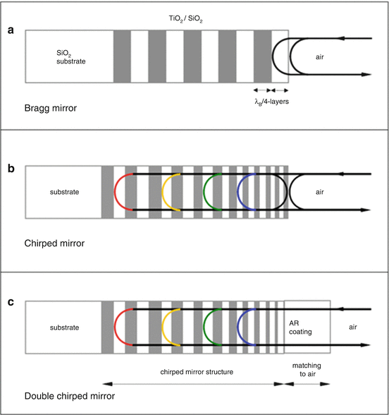
Fig. 19.1
Mirror technology for Ti:sapphire lasers. Comparison between Bragg mirror (a), chirped mirror (b), and double-chirped mirror (c)
19.2 Ti:Sapphire Laser Development
Recent advances in laser technology resulted in development of ultrafast solid-state lasers capable of emitting powerful spectra with bandwidths spanning several hundred nanometer at full width at half maximum (FWHM) [13]. Pulses in the 8–10 fs range can easily be generated from prism-pair oscillators. Since pulse duration has been pushed towards the theoretical limit of one optical cycle, which is approximately three femtosecond, accurate dispersion control over a broad wavelength range is demanded, and dispersion effects have to be minimized in the design of these femtosecond lasers. The two major sources of dispersion in a mode-locked laser are self-phase modulation that is a part of the Kerr effect and normal dispersion in the laser crystal or any other optical component in the resonator.
Pulses significantly shorter than 10 fs could be generated from mirror-dispersion-controlled oscillators, whereas oscillators employing both prism pairs and chirped mirrors for dispersion control allowed the generation of sub-6 fs pulses. Moreover, external spectral broadening in special fibers, pumped by ultrashort (picosecond to femtosecond) laser pulses, enabled the generation of so-called supercontinua (SC). While the bandwidth of a solid-state laser is limited by the gain spectrum of the laser crystal as well as the mirror technology, nonlinearly broadened light sources utilizing microstructured fibers like photonic crystal fibers (PCF) [14] or tapered fibers [15] do not exhibit such limitations. Spectra covering more than one octave or even more than two octaves are generally achievable. However, this kind of external broadening often results in significant power fluctuations, spectral modulations, and excess noise (in addition to the noise of the pump source) [16, 17] in the optical output, which limit clinical applications of OCT. Therefore, it is desirable to generate an ultrabroad spectrum directly from a compact solid-state laser. Octave-spanning (at the pedestal) Ti:sapphire lasers that use chirped mirrors in combination with prism pairs and some other intracavity elements such as a glass plate for enhanced self-phase modulation with a two-foci laser for broadening were demonstrated [18]. It was also demonstrated that a broad bandwidth optical output can be generated by self-phase modulation in a Ti:sapphire crystal in a prismless oscillator [19]; however, the spectra exhibited strong modulations, severely compromising applications where a clean temporal structure of the generated pulses or the first-order autocorrelation of the laser output is essential. The latter requirement applies to ultrahigh-resolution and spectroscopic OCT [20–22]. Further limitations of all these systems were the need of highly sophisticated, bulky, and very expensive pump sources and the lack of reliability and long-term stability. Each system represented a unique laboratory prototype with almost no chance of doubling. OCT imaging on a daily base was not feasible. With advanced mirror technology the generation of ultrabroad bandwidth (>277 nm at FWHM) and smooth spectra directly out of a prismless Ti:sapphire was reported [23].
19.2.1 Mirror Technology for Femtosecond Pulse Ti:Sapphire Lasers
Standard dielectric quarter-wave Bragg mirrors are inappropriate for the generation of sub-10 fs pulses because of their restricted high-reflectance bandwidth and the strong higher-order dispersion near the edges of the HR range. Metal mirrors do not experience these restrictions, but suffer from high insertion losses. Nevertheless, the first sub-10 fs pulses directly from an oscillator were achieved by using silver mirrors instead of dielectric mirrors and additional prism pair for dispersion control [10]. However, considerable residual higher-order dispersion prevented such lasers from producing pulses shorter than ∼8.5 fs. This restriction demanded alternative methods for dispersion compensation. Even for propagation in air, the group velocity of electromagnetic signals depends on the carrier frequency. Ultrashort pulses contain broad frequency spectra, and the varying propagation speed of the different spectral components will always cause the pulse to change its shape during propagation. Optimal performance can only be obtained if all spectral components arrive at the same time meaning that the spectral phase is the same for all frequency components. Such pulses are called “transform limited” because they have a minimum root-mean-square time-bandwidth product. By introducing dispersive materials in the beam path, the resulting group delay between different spectral components will lead to a pulse whose instantaneous frequency (the derivative of the temporal phase with respect to time) depends on time. Such pulses are called “chirped.” There are attributes like “down-chirped,” “up-chirped,” and “unchirped” for a pulse whose instantaneous frequency falls (blue-first, negative chirp) or rise (red-first, positive chirp) with time or remain constant (“transform limited”). Parallel to the standard design approach, chirped mirror technology allows minimizing the system complexity.
For ultrashort pulse generation, the round trip time τr in the resonator for all frequency components of the mode-locked pulse must be the same, i.e., τ r = dφ/dυ = constant, where φ is the phase change after one round trip. Otherwise, frequency components that experience a cumulative phase shift no longer add constructively and are attenuated. This limits the bandwidth of the pulse and leads to pulse width broadening. The frequency-dependent phase shift of the pulse during one round trip can be expressed in a Taylor series about the center frequency v 0,
 with φ′, φ″ and φ‴ as the derivatives of the phase with respect to frequency. When φ″ is nonzero, the pulse will have a linear frequency chirp, while a nonzero third-order dispersion will induce a quadratic chirp on the pulse.
19.2.1.1 Quarter-Wave BRAGG Mirrors
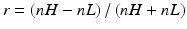
Standard high-reflectance laser mirrors typically consist of quarter-wave stacks (cf. Fig. 19.1) and therefore are limited in the maximum reflectance which is given by the BRAGG wavelength λ B that is twice the optical thickness of the unit cell defining the quarter-wave structure. It can be seen that in the stop band around the angular frequency ω B = 2πc/λ B , the condition (cos ϕ − r²)/(1 − r²) ≤ − 1 holds, where ϕ = πω/ω B is the phase acquired after propagation through a layer pair and where Fresnel’s reflectance for the index step is given by
(19.15)
The stop band covers the wavelength range between λ St = nλ B /[2π − 2(arc cos(r))] and λ St = πλ B /2arc cos(r) only in an ideal case when the wavelength dependence of the refractive index is neglected. Then its fractional width Δω/ω B depends only on the index ratio between the high- and the low-index material:
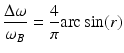
(19.16)
For epitaxially grown semiconductor quarter-wave mirrors, all refractive indices are typically between 3.0 and 3.6, enabling bandwidths of about 10 %. For amorphous coatings, typical materials with low indices are between MgF2 (n = 1.37) and SiO2 (n = 1.44), and high-index materials like Ta2O5 (n = 2.1) and TiO2 (n = 2.35), which results in fractional bandwidths of about 30 %.
The maximum achievable reflectance in case of small absorption coefficients α H,L for an infinite number of layers [24] is approximately given by R(λ B ) = R 0(λ B )[1 − (λ B /2)(α H + α L )n I /(n H 2 − n L 2)]. So the maximum reflectance of a quarter-wave mirror can be assumed for a lossless quarter-wave mirror and is given by
(19.17)
It will already be approached for a limited number of layers. Assuming that the absorption in the mirror can be neglected which is especially valid for ion-beam sputtered coatings made of TiO2 and SiO2, the maximum reflectance will approach unity with increasing layer pairs. Since quarter-wave mirrors introduce significant amounts of negative dispersion for wavelengths λ > λ B , they can be used for dispersion compensation over a small region of their high-reflectance bandwidth. Broadband mirrors can be designed by several quarter-wave sections whose stop bands overlap. Since such mirrors exhibit regions of extreme phase variations, they cannot be used for femtosecond or OCT applications.
19.2.1.2 Chirped Mirrors
UHR OCT demands for ultrabroad Gaussian-like stable spectra generated directly out of the Ti:sapphire. The proper choice of broad bandwidth dispersive mirrors is mandatory for accurate dispersion compensation in the spectral range approaching or even exceeding one optical octave (cf. Fig. 19.1). These mirrors have contributed significantly to enhancement of the performance, compactness, and reliability of femtosecond laser sources. The generation of sub-10 fs pulses directly from the oscillator can now be achieved routinely with CM dispersion-controlled oscillators. Progress in CM design and manufacturing in combination with advanced oscillator designs have permitted the direct generation of sub-6 fs pulses. Such extreme bandwidths create new challenges and difficulties making some of the small-bandwidth approaches ineffective and deserve special treatment.
CMs are custom-tailored multilayer dielectric mirrors, where the thickness of each layer is carefully chosen so that the whole system has special dispersion properties. The BRAGG wavelength is gradually decreased during deposition (at least in the initial design, which may be altered by subsequent computer optimization) so that the incident light is reflected with a wavelength-dependent group delay. The average group delay of such simple chirped mirrors can be increased with wavelength, but with the drawback of the superimposing of a strong wavelength-dependent dispersion oscillation [25]. The mirror consists of a large number (∼40) of alternating low- and high-refractive index layers whose thickness progressively increases going towards the substrate. Layers with increasing thicknesses (e.g., quarter-wave layers with a gradually increasing local Bragg wavelength) are stacked such that longer wavelengths penetrate deeper into the mirror structure, producing negative group delay dispersion (GDD). Due to the chirp of the Bragg wavelength, the high-reflectivity bandwidth is larger compared to standard dielectric quarter-wave mirrors. Both features together allow for a more efficient compensation of higher-order dispersion over a broader spectral range. Interference of light waves reflected from different plane-parallel interfaces results in a certain frequency-dependent reflectance R(λ) and phase shift φ(λ) of the incident light, where φ(λ) is directly connected to the group delay (GD) and the GDD introduced by the mirror:
It is the same principle that works in the Bragg reflectors (stack of layers with a fixed optical thickness equal to λ 0/4). But CMs possess another very important property: they can be designed in such a way that the frequency-dependent phase shift φ(λ) matches dispersion properties of materials common in laser systems (air, fused silica, or Ti:sapphire), which is essential for the generation of ultrashort pulses. A desirable dispersion can be achieved if optical layer thicknesses gradually change along the coating, so that a component with wavelength λ is reflected from the part of the stack, where the optical thickness of layers is close to λ/4. This gradual change of optical layer thicknesses is referred to as “chirping”; hence, this type of mirror is named “chirped mirror.”
The GD of the reflected beam increases with decreasing values of ω, thus giving ϕ″ < 0. One can obtain a value of ϕ″ that, within the bandwidth of interest, is approximately constant with frequency ϕ‴ ≅ 0, but the GDD can also be designed to exhibit a slight linear variation with frequency and a slope suitable for compensating the TOD of other cavity components. GDD per bounce is in general −50 fs2.
Of particular interest are the so-called double-chirped mirrors: an analytic approach based on the coupled-mode theory for multilayer interference coatings. In this approach, a chirped mirror is composed of Bragg cells, where each cell is characterized by a corresponding Bragg wavelength and the thickness of the high-refractive index layer. Both these parameters are chirped in order to achieve a smooth increase of the coupling coefficient, which was recognized as a prerequisite for suppression of GDD oscillations [26]. A perfect AR coating is assumed to match the impedance from air to the first low-index layer. Although the recently found improved implementations and the analytical predesign methods were essential for enhancing the performance of CMs, they did not obviate the need for efficient computer optimization techniques. On the one hand, the request for mirror designs with even larger bandwidth, which would permit the generation of nearly single-cycle pulses for scientific applications, makes the requirements for chirped mirrors extreme that even small improvements may play a crucial role. On the other hand, the high production cost of chirped mirrors demands designs with reduced sensitivity to small discrepancies between the layer thicknesses of a calculated design and those of the manufactured mirror, especially if the mirror is designed for a broad spectral range.
Nevertheless, impedance matching with AR coatings or edge filters can only be achieved over a limited bandwidth. This drawback can be overcome by coating the CM on a thin wedged substrate and illuminating it from the substrate side. With this approach, the incident medium is glass (to which the multilayer can be perfectly impedance matched over an arbitrary broad bandwidth). The impedance mismatch will occur now at the substrate air interface, resulting in an additional reflected beam. This beam will not distort the GDD characteristic of the mirror because it cannot interfere with the main (useful) beam, having a different propagation direction. TFICM (tilted-front-interface chirped mirrors) [27] might allow enhancing the bandwidth of pulses emitted directly from the oscillator far beyond 300 nm.
19.2.2 Ultrabroad Bandwidth Ti:Sapphire
19.2.2.1 Sub-Two-Cycle Pulse Oscillator with Intracavity Prisms
In the early days of OCT a Ti:sapphire laser with 4 μm axial resolution has been used for in vitro OCT imaging in nontransparent tissues to improve OCT axial resolution [6]. Consequently, in preliminary UHR OCT studies, a system was developed and could be optimized to support 260 nm of optical bandwidth from a state-of-the-art Ti:sapphire laser [28] resulting in 1 μm axial resolution [20, 21].This laser generated pulses of <5.5 fs duration corresponding to bandwidths of more than 350 nm at 800 nm center wavelength. This high performance was achieved using specially designed double-chirped mirrors with high-reflectivity bandwidth and controlled dispersion response. The resonator was a standard z-fold design, as shown in Fig. 19.2a. Figure 19.2b depicts the measured reflectivity of the DCM and the output-coupling mirror (OC) (top), the desired condition for perfect dispersion compensation, and the designed and the measured GDD of one bounce on the DCM (second from top), the measured spectrum behind the output coupler (third from top), as well as the measured intracavity spectrum with a silver mirror instead of the output coupler (bottom). An interferometric autocorrelation as shown in Fig. 19.2c was accomplished. A fit to the interferometric autocorrelation of a sech-shaped pulse would result in a pulse width of 4.3 fs FWHM, a fit to a Gaussian in 4.8 fs. The most conservative assumption for the pulse shape is the sinc function and results in 5.4 fs. The good agreement of the measured interferometric autocorrelation with those derived from the spectrum and the sinc function indicates a pulse width between 4.9 and 5.4 fs, which is shorter than two optical cycles at the center wavelength of 800 nm.
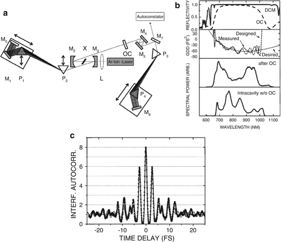
Fig. 19.2
Sub-two-cycle pulses from a Kerr-lens mode-locked Ti:sapphire laser. Cavity setup (a) with crystal X; curved mirrors M2 and M3; flat mirrors M0, M1, and M4, M7; output-coupling mirror OC; and prism sequence P1, P2. All double-chirped mirrors (DCM’s) are gray; the other mirrors are silver mirrors. Lens L focuses the pump beam into the crystal. The prism sequence P3, P4 is necessary for extracavity dispersion compensation. (b) Depicts the measured reflectivity of the DCM and the output-coupling mirror (OC) (top), the desired condition for perfect dispersion compensation, and the designed and the measured GDD of one bounce on the DCM (second from top), the measured spectrum behind the output coupler (third from top), as well as the measured intracavity spectrum with a silver mirror instead of the output coupler (bottom). (c) Measured interferometric autocorrelation of the Ti:sapphire laser. The dashed curve is a fit of a sinc2 function with a FWHM of 5.4 fs, and the solid curve is the calculation from the spectrum [28]
Necessary light source specifications for ultrahigh-resolution OCT include not only spatial coherence, ultrabroad bandwidth emission with enough output power, and good amplitude stability but also optimum spectral shape. Since the coherence length is defined as the full width at half maximum of the field autocorrelation measured by the OCT interferometer, the width and also the shape of the coherence function of an OCT system are dependent on the spectral shape of the light source as well as on the transfer function of the OCT system. The latter one is mainly determined by the optical properties of the interferometer, e.g., wavelength-dependent losses and splitting ratios of beam splitter and lenses, as well as cutoff wavelength of employed single-mode fibers as well as the wavelength-dependent sensitivity of the employed photodetectors. The ideal spectrum for OCT would have Gaussian spectral shape, resulting in a Gaussian coherence function with no sidelobes. Large spectral modulations would reduce sensitivity and resolution, due to the presence of sidelobes in the fringe pattern that appear symmetrically to the coherence functions maximum. There are several possibilities to change the shape of the emission spectrum of the used light source. The easiest way is to introduce optical dichroic or interference filters that suppress certain wavelength regions. Another possibility is to spatially disperse the optical beam with prisms and to induce local and therefore wavelength-dependent losses by introducing razor blades or thin objects into the dispersed light beam. Figure 19.3a demonstrates the effect of this shaping method when applied to a strongly modulated spectrum of the sub-two-cycle pulses from the Kerr-lens mode-locked Ti:sapphire laser described above (cf. Fig. 19.2). It also shows a comparison of the spectra and resolution (Fig. 19.3b) of an OCT A-scan using a conventional superluminescent diode light source versus this femtosecond Ti:sapphire laser source. The ultrabroad bandwidths which are generated by the femtosecond laser enable the axial resolution of OCT to be improved by a factor of nearly 10× better than standard OCT technology.
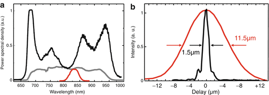
Fig. 19.3
Ultrahigh-resolution OCT using a sub-two-cycle pulse Kerr-lens mode-locked Ti:sapphire laser. Original spectrum from Ti:sapphire (a, black) and reshaped spectrum (a, gray) using wavelength-dependent attenuation compared to a spectrum from a standard superluminescent diode (a, red). (b) Demodulated OCT axial scan showing the axial resolution of OCT using this Ti:sapphire (black) versus a standard superluminescent diode SLD (red) light sources. Solid-state lasers enable almost a 10× improvement in resolution [21]
19.2.2.2 All-Chirped Mirror Oscillator (ACM Oscillator)
An ultrabroad bandwidth complementary chirped mirrors pair, compensating for Ti:sapphire dispersion in the wavelength range 600–1,000 nm with maximal spectral intensity loss of 1 %, has been designed for an all-CM oscillator (cf. Fig. 19.4) [23].To design these mirrors, a suitable compromise between the bandwidth, dispersion, and reflectance has to be found. A major goal was to keep the dispersion fluctuations of each mirror as small as possible since we found that in this way, we can improve the manufacturing reproducibility of the design. Each of the mirrors consists of 63 layers. If the mirror is used in pair with the input coupler, the net GDD and the net reflectance are closer to their targets. The small positive second-order dispersion of the complementary mirror can be compensated with other chirped mirrors. For the implementation of CMs in an octave-spanning oscillator, the previously designed complementary pair of an input coupler (IC) and a chirped mirror (CM) has to be redesigned. The IC has transmission >99 % in the wavelength range 525–539 nm. Both IC and CM have reflectance >99.5 % in the range 625–1,110 nm, as well as a “smooth” dispersion in the range 700–1,100 nm.
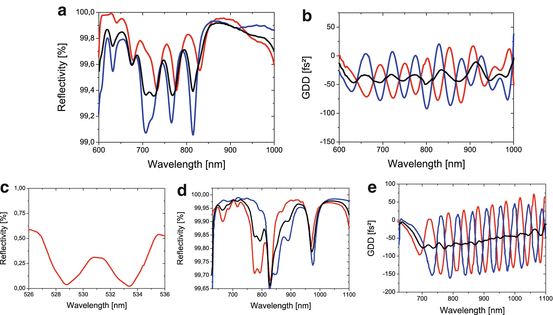
Fig. 19.4
Chirped mirror technology for ultrabroad bandwidth Ti:sapphire lasers. Reflectance (a) and GDD (b) of a chirped mirror pair. A broadband input coupler (c, d) and a complementary chirped mirror (e)
Optimization of Ti:sapphire oscillators has resulted in lasers with short (few millimeters) highly doped active media – 2–3 mm in the experiments mentioned in the previous paragraphs. Consequently, the amount of positive dispersion to be compensated is limited and can be balanced by using 4–6 bounces of CMs. The total number of bounces of cavity mirrors is typically higher. One would thus be inclined to use a minimum number of CMs and employ the much cheaper and easier to manufacture standard Bragg mirrors (BMs) in addition. Although TiO2/SiO2 BMs exhibit high reflectance over ∼200 nm at 800 nm (bandwidths that can support pulses with 120–140 nm at FWHM), the range within which GDD remains constant is smaller. Furthermore, deviations from GDD = 0 add up constructively, as all BMs have identical dispersion. In an oscillator employing both CMs and BMs, the bandwidth over which mode locking can be achieved is severely limited by the range within which the GDD of BMs remains constant. With accurate dispersion management, spectra slightly below 200 nm at FWHM are feasible. Nevertheless, a lot of effort is needed to obtain such spectra, and no reliable performance and reproducibility can be expected. In such laser cavities, BMs with enhanced transmittance at the pump wavelength have been widely used as input couplers because design and particularly manufacturing of dichroic CMs rise serious problems (mainly because of the high sensitivity of the dichroic CMs transmittance to manufacturing errors). However, comparing the dispersion and reflectance characteristics of BMs and dichroic CMs, the advantages of the latter are overwhelming. With the advent of highly accurate deposition methods like magnetron sputtering tailored for CM coatings, manufacturing of dichroic CM has become possible. As the dichroic BM input coupler acted so far as a bottleneck on the bandwidth of the mode-locked pulsed lasers, there was no motivation to replace other BMs in the cavity with broader bandwidth CMs. Nevertheless a Ti:sapphire oscillator employing dichroic CMs enormously benefits in terms of bandwidth and pulse duration if all the other reflectors in the cavity are CMs.
Therefore, further increasing of the bandwidth using a compact oscillator design is feasible by replacing all high-reflecting mirrors by broadband dispersive mirrors and employing a single frequency 532 nm pump source on a platform of 600 × 400 mm. Ultrabroad bandwidth and smooth spectra from a prismless Ti:sapphire laser can be generated making additional external shaping not longer necessary.
Therefore, two main goals had to be followed in the development of dispersive dielectric multilayer coatings:
One effort was the increasing of the bandwidth of chirped mirrors from 200 nm to as large as possible (>400 nm)
Simultaneously search for a technology suitable for the accurate and reproducible high-yield production of CM in large quantities
Fulfilling these two criteria a laser formed by a standard x-folded resonator [29] composed of chirped, mirrors, a broadband output coupler, and a pair of wedges for fine tuning the dispersion in the cavity was built. The major benefit of the prismless laser is the compactness and stability of the cavity. The generated spectrum has a 277 nm bandwidth at FWHM and with only 2 dB spectral modulation. In addition, the spectral bandwidth is ∼380 nm at −10 dB below its maximum, which is suitable for phase stabilization and frequency metrology based on interference of second- and third-harmonic light [30, 31]. The schematic of the laser cavity is shown in Fig. 19.5a. The laser is pumped by a diode-pumped, frequency-doubled Nd:YVO4 laser (Verdi, Coherent Inc.). The thickness and the absorption coefficient of the Ti:sapphire crystal are 2.5 mm and 5.0 cm−1, respectively. The radius of curvature of the concave mirrors is r = −50 mm. All-chirped mirrors in the cavity were designed for minimal fluctuations and manufactured by Layertec GmbH. The transmission of the output coupler is 10 %. A pair of thin fused silica wedges is inserted at the Brewster’s angle for intracavity dispersion control. The prismless laser generates an average output power of 250 mW for 3.65 W pump power and 64 MHz repetition rate.
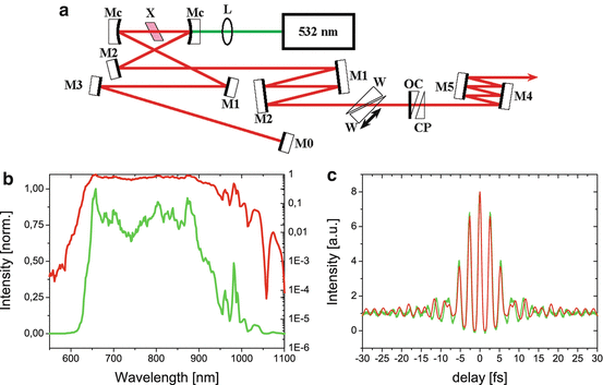
Fig. 19.5
Ultrabroad bandwidth Ti:sapphire. Schematic of prismless Ti:sapphire laser with extracavity dispersion control (a). L incoupling lens, Mc dichroic input coupler, M1-5 dispersive mirrors, W wedge, OC output coupler, CP compensating plate. (b) Spectrum generated from the mirror-dispersion-controlled oscillator depicted on a logarithmic and linear scale. (c) Measured and reconstructed interferometric autocorrelation traces of the pulse. A phase-retrieval algorithm reveals a pulse width of 6.5 fs. The red line shows the retrieved IAC trace from the Spider measurement [23]
The spectrum generated from the oscillator and measured with an optical spectrum analyzer with single monochromator mode is shown in Fig. 19.5b in linear (green) as well as logarithmic representations (red). The bandwidth of the spectrum is 277 nm (141 THz) at FWHM. The fine spectral modulations at long wavelengths are caused by vapor absorption and/or the structure of the reflectivity spectrum of the chirped mirrors in the cavity. On the logarithmic scale, spectral components can be observed at ∼625 nm and 1,005 nm at −10 dB below maximum. Although the chirped mirrors and the output coupler only support a spectrum from 700 to 900 nm, the generated spectrum from the oscillator extends beyond this region. This means that most of the light at the wings of the spectrum is not generated through lasing but by self-phase modulation in the crystal, a phenomenon previously observed [32]. The output pulses are compressed by six reflections of the chirped mirrors, and the temporal characteristics of the pulses are measured using an interferometric autocorrelator designed for sub-10 fs pulse diagnostics (Femtometer, Femtolasers Produktions GmbH). The frequency-doubling crystal is a 10 μm thick BaB2O4 (BBO) crystal (type I, Θ = 29°). Figure 19.5c shows the measured interferometric autocorrelation trace (IAC). The FWHM of the intensity envelope has been evaluated as 6.5 fs by using a phase-retrieval algorithm.
Stay updated, free articles. Join our Telegram channel

Full access? Get Clinical Tree


