The role of preoperative imaging has been the subject of debate among those who perform chronic ear surgery. It has been argued that preoperative imaging of the chronic ear is beneficial because it provides a thorough understanding of the patient’s anatomy and improves efficacy and safety of surgery.1 Alternatively, others contend that routine imaging is not indicated because the diagnosis of chronic ear disease is made clinically, not radiographically, and the surgical management of chronic ear disease is mainly dictated by intraoperative landmark identification and decision-making.2 Whereas there is controversy regarding the role of routine preoperative imaging for chronic ear disease, most agree that it is indicated for patients in whom a complication of chronic otitis media or a congenital malformation is suspected. Some also believe that routine imaging is also called for in the rare instance when surgery is indicated in an only-hearing ear.
What then, is the role for imaging in chronic ear disease? In this chapter, we will review the typical imaging characteristics of chronic ear disease, illustrate how imaging can aid in diagnosing many of the complications of chronic ear disease, and review how new imaging modalities can be useful for surveillance of chronic ear disease in the postoperative setting. For clarity in defining chronic otitis media, this chapter primarily deals with chronic suppurative otitis media caused by cholesteatoma.
11.2 Imaging Characteristics of Chronic Ear Disease
The diagnosis of chronic ear disease is primarily based on a comprehensive history and physical exam, including otomicroscopy and an audiogram. Despite the fact that the diagnosis is made based on this clinical information, imaging can provide useful adjunct information, such as anatomic information about the extent of disease for patients with cholesteatoma. There is a high reported correlation between temporal bone computed tomography (CT) findings in determining the presence, location, and extent of cholesteatoma, ossicular chain erosion, labyrinthine fistula, and intracranial complications.3,4
11.2.1 Extent of Disease and Degree of Pneumatization
Primary acquired cholesteatomas typically develop in the epitympanum from a posterior-superior retraction of the pars flaccida portion of the tympanic membrane.5 As the cholesteatoma enlarges, the adjacent osseous structures become involved and are eroded. Cholesteatomas involving the epitympanum will often erode the scutum, the normally sharp bony overhang lateral to the head of the malleus (▶ Fig. 11.1). Epitympanic cholesteatomas will cause erosion or blunting of the scutum (▶ Fig. 11.2), which is best seen on a coronal CT scan.
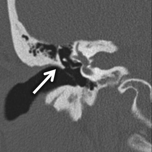
Fig. 11.1 Coronal bone algorithm CT through the right ear demonstrates a sharp scutum (arrow) at the superior attachment of the tympanic membrane.
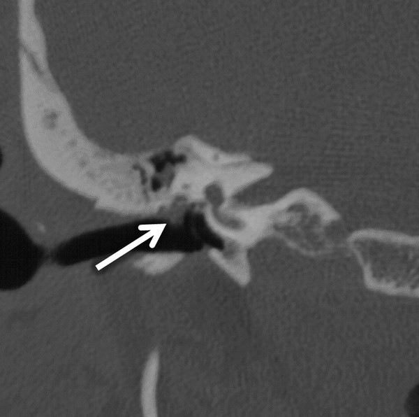
Fig. 11.2 Coronal bone algorithm CT through the right temporal bone shows a soft tissue mass (arrow) at the expected location of the pars flaccida portion of the tympanic membrane, found to be an epitympanic cholesteatoma eroding the scutum.
Whereas there is not a strict correlation to the degree of mastoid pneumatization and severity of chronic ear disease or risk of developing a cholesteatoma, it is generally accepted that poor pneumatization is evidence of chronic ear disease. Poor pneumatization has been associated with pars flaccida cholesteatomas.6 A spectrum of temporal bone pneumatization is illustrated in ▶ Fig. 11.3.
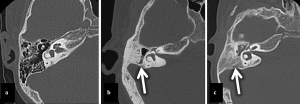
Fig. 11.3 Stage of pneumatization. Three axial CT images in three different patients. The first image (a) demonstrates well-pneumatized and well-aerated mastoid air cells in the middle ear of a normal healthy patient with normal hearing. The second image (b) shows a more poorly pneumatized mastoid bone compared to the example in (a) with dense cortical bone with aeration of only the mastoid antrum (arrow). The last image (c) shows no pneumatization, with a small opacified middle ear surrounding the ossicles. Bone density extends lateral to the lateral semicircular canals (arrow).
Preoperative imaging can influence a surgeon’s choice of surgical approach. The more information the surgeon has to augment the preoperative examination, the better he or she is able to plan what needs to be done surgically as well as to appropriately counsel the patient with regard to expectations and knowledge of risks.1 For example, disease isolated to the epitympanum may only require a transcanal atticotomy. However, a preoperative scan that shows a poorly pneumatized mastoid with minimal disease may allow an otologic surgeon to prepare for and counsel the patient regarding a possible canal wall-down tympanomastoidectomy. This information may lead to shorter operating time given that an “inside out” mastoidectomy can be done at the outset, which involves lowering the posterior external auditory canal wall while the initial mastoidectomy is being performed. A canal wall-down tympanomastoidectomy in patients with contracted, sclerotic mastoids essentially creates an enlarged ear canal rather than a large mastoid bowl, which is found in patients with more extensive pneumatization.
11.2.2 Anatomy of Critical Structures
Preoperative imaging in chronic ear disease allows the otologic surgeon to evaluate the location of certain critical landmarks, namely the tegmen, sigmoid sinus, and vascular structures as well as the course of the facial nerve. Whereas the temporal line is the typical external landmark used to identify the level of the tegmen and floor of the middle fossa, the true level can be quite variable. Coronal CT imaging will provide the best views of the tegmen (▶ Fig. 11.4). The tegmen is typically lower laterally and then rises in its more medial course. A low tegmen can have a significant effect on the exposure of the epitympanum and antrum in canal wall-up surgery.1
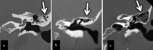
Fig. 11.4 Three coronal CT images from different patients all at the level of the external auditory canal. Various tegmen tympany configurations are shown, with a downward-sloping lateral portion (a, arrow), relatively flat tegmen (b, arrow), and an upward lateral sloping tegmen (c, arrow).
Imaging of the facial nerve in chronic otitis media can alert the surgeon about possible areas of dehiscence or an aberrant course of the nerve. This radiographic information can be especially useful when doing revision chronic ear surgery since the facial nerve can be exposed at the initial operation.7 With regard to managing the facial nerve during chronic ear surgery, it is especially important to emphasize that a thorough knowledge of facial nerve anatomy, sound clinical judgment, careful surgical technique, and experience remain the cornerstones for avoiding facial nerve injury.1 The majority of iatrogenic injuries result in failure to recognize key intraoperative landmarks.8 Cholesteatoma can cause bony dehiscence adjacent to the facial nerve in the middle ear and mastoid (▶ Fig. 11.5). Cholesteatomas that form in the anterior epitympanum can erode bone adjacent to and exert pressure on or local irritation to the geniculate ganglion, which can result in facial paralysis.9
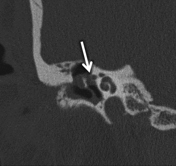
Fig. 11.5 Coronal CT through the right temporal bone showing a cholesteatoma as a soft tissue mass within the middle ear with erosion of the lateral wall of the proximal portion of the tympanic segment of the facial nerve (arrow).
11.2.3 Identifying Postoperative Features
When imaging patients with chronic ear disease who have had prior surgery, it is vital to recognize important postoperative features. One such feature is the appearance of various ossicular prostheses. Ossicular prostheses are commonly categorized based on their length, material, and whether or not they make contact with an intact and mobile stapes. The radiolucency of the material affects how well the prosthesis can be visualized radiographically (▶ Fig. 11.6). Prostheses that are placed on a mobile stapes are often referred to as partial ossicular replacement prostheses (PORPs). Prostheses that bridge the gap from the tympanic membrane to the footplate in the absence of a stapes superstructure are called total ossicular replacement prostheses (TORPs).
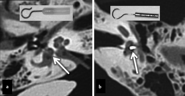
Fig. 11.6 Examples of stapes prostheses. Two axial temporal bone CT examinations showing different types of stapes prostheses, with a radiolucent (a, arrow) fluoroplastic prosthesis (a, insert), and a radiodense (b, arrow) stainless steel prosthesis (b, insert).
The postoperative hearing result following ossiculoplasty can be predicted with imaging. Postoperative imaging can precisely determine the position and angle of middle ear implants.10 For example, in patients who have a significant persistent, postoperative conductive hearing loss, imaging may reveal a misplaced or dislocated prosthesis (▶ Fig. 11.7). Komori, Yanagihara, Hyodo, and Miuchi reported that volume-rendered 3-dimensional cone-beam CT (CBCT) images revealed TORP malpositioning or migration, which was not detected on 2-dimensional CBCT images.11 In such cases, the TORP shaft was in contact with the wall of the oval window niche or the TORP had moved from the stapes footplate.
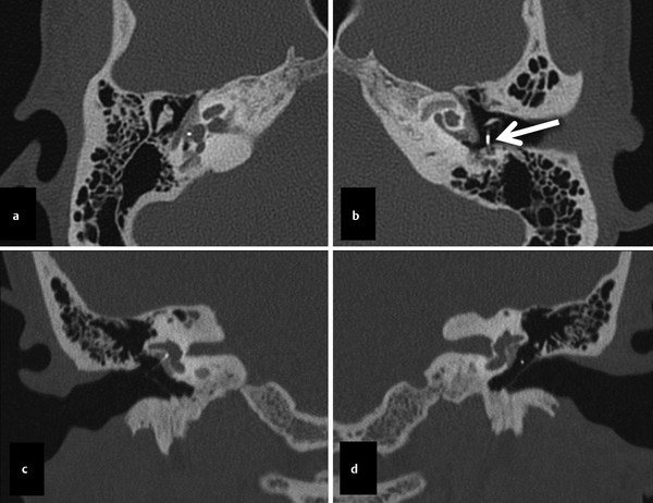
Fig. 11.7 Patient with bilateral stapes prostheses for bilateral cochlear otosclerosis (otospongiosis). The axial (a) and coronal (c) right-sided images show a normal right-sided prosthesis. The correlating left sided axial (b) and coronal (d) images show a misplaced left-sided prosthesis (arrow in panel b), extending posteriorly adjacent to the descending segment of the facial nerve.
For patients who have postoperative complications following ossiculoplasty, imaging can often be helpful in making a diagnosis. For example, if a patient experiences postoperative sensorineural hearing loss or vertigo, the prosthesis may have been inserted too deeply and may have violated the inner ear (▶ Fig. 11.8).
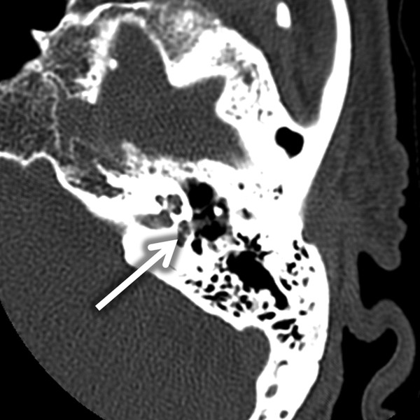
Fig. 11.8 Stapes within vestibule. Imaging can provide insight into postoperative complications with chronic ear surgery. This axial, temporal bone CT illustrates a PORP that has displaced the stapes into the vestibule (arrow), causing postoperative vertigo and sensorineural hearing loss.
Stay updated, free articles. Join our Telegram channel

Full access? Get Clinical Tree


