The Human Eye as an Optical System
Milton Katz
Philip B. Kruger
Introduction
The eye is a compound optical system composed of a cornea and a lens shown in Figure 1. It is an adaptive optical system because the crystalline lens changes shape to focus light from objects at a large range of distances on the retina. Unlike the components of most optical systems, typified in Figure 2, the cornea and lens are not centered on a common axis nor are they spherically surfaced. Because a model eye is being treated here, it will be assumed that the surfaces are spherical and that their centers of curvature lie on the optical axis, a straight line from the vertex of the cornea to the posterior pole. Furthermore, the incident rays will be considered paraxial (i.e., they lie close to the optical axis and strike the surfaces with very small angles of incidence) (Fig. 3). A bundle of paraxial rays converges to a single point focus. As the diameter of the bundle of rays grows larger, the incidence angles of the marginal rays become larger so that they no longer may be considered paraxial. Spherical aberration forces them to cross the axis at different points, thus blurring the image as illustrated in Figure 4. A 2-mm maximal pupil diameter for the eye satisfies paraxial assumptions.
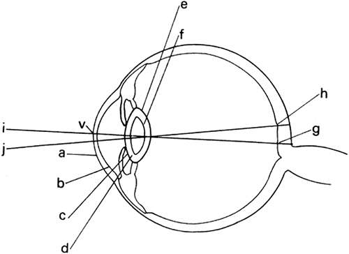 Fig. 1. Optical system of the eye: a, anterior surface of cornea; b, posterior surface of cornea; c, anterior cortex; d, anterior core, e, posterior cortex; f, posterior core; v and g, anterior and posterior poles of the eye through which the optical axis passes; line jh, visual axis. |
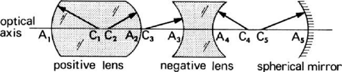 Fig. 2. Centered system of rotationally symmetric optical elements containing an optical axis. |
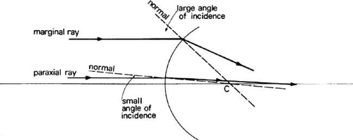 Fig. 3. Increasing angle of incidence for rays striking a spherical surface at increasing heights above the optical axis. |
 Fig. 4. The blur due to spherical aberration has radial symmetry. |
Briefly, the corneal portion, including the tear layer, separates air from aqueous humor and the lens portion separates aqueous from vitreous humor. Rays entering the eye are refracted first and by the greatest amount at the first surface of the cornea because of the large difference in index of refraction at the air-to-cornea interface. The second surface of the cornea has negative power; nevertheless, the cornea contributes >70% of the approximately 64 diopters (D) of refractive power of the unaccommodated eye. The crystalline lens supplies the remaining refractive power. During accommodation, additional power is supplied by the lens which assumes a rounder form.
History
The nature of the ocular image has been studied since the times of the ancient Greeks. Galen1 hypothesized that a psychic spirit moved through a hollow optic nerve to the retina and crystalline lens into the anterior chamber and was projected out of the eyes as an emanation of rays that made objects in space visible. The crystalline lens was the main receptor that somehow created the visual sensation that traveled back as a visual spirit through the optic nerve to the brain. Galen’s theories were preeminent in Europe until the Renaissance.
Following the decline of Greek civilization and during the Dark Ages in Europe, the most important physicist was Alhazen (965–1039). He was especially interested in optics and made notable contributions in the study of reflection and refraction of light. He constructed a pinhole camera and parabolic mirrors and studied the rainbow and the properties of lenses. In his Book of Optics, he clearly expressed the view that light emanated from luminous sources such as the sun and was reflected from the object to the eye. Although he believed that an image was formed in the eye, he was unsure of its precise nature owing to inadequate appreciation for the refractive properties of the ocular media. Only 600 years later, with the contributions of Kepler, did the understanding of optics progress significantly beyond Alhazen’s ideas.
Much work was done in optics during the Renaissance. Spectacles were applied to correct vision; the telescope and microscope were discovered; and the belief steadily grew that the eye formed an image in the same way as a pinhole camera. The greatest difficulty, however, was experienced in reconciling that the image was inverted with our perception of the world. Even Leonardo da Vinci, whose notebooks were mirror written, could not accept the idea of an inverted retinal image, and attempts to construct erect images hindered a true understanding of the optics of the eye.
The German astronomer, Johannes Kepler (1571–1630), explained the role of the crystalline lens in the image-forming process. Points in space were imaged on the retina to form an inverted, real image owing to refraction by the cornea and lens. Proof of the correctness of Kepler’s hypothesis was given by Christopher Scheiner (1573–1650) who removed part of the sclera and choroid from enucleated sheep eyes to reveal the back of the retina. While pointing the eye toward a bright object, he observed a small inverted image on the retina.
Once it was realized that the formation of the ocular image depended on the curvatures and spacings of the ocular refracting surfaces and the refractive indices of the ocular media, accurate measurements of these elements were evidently essential if the dioptrics of the eye were to be understood. Although anatomic measurements and index of refraction determinations of cadaver eyes were easy to obtain, severe problems in making in vivo determinations remained. One such measurement was ingeniously made by Scheiner who recognized that the cornea of the eye was a convex mirror whose reflex image could provide a measure of the curvature of the cornea:
For this purpose, he used a series of small glass marbles of various sizes from about 10 to 20 millimeters in diameter. The patient whose eye was to be measured was seated opposite a bright window where the image of the crossbars in the sash could be distinctly observed. First one marble and then another was inserted in the corner of the eye until at length one was found which gave a reflex image as nearly the same size as possible as that seen in the cornea: whence it might be inferred that the radius of curvature of the anterior surface of the cornea was at least nearly the same as that of the marble.2
Nevertheless, the lack of sufficiently accurate data, even as late as the 17th century, frustrated Christiaan Huygens (1629–1695) in the construction of an optical model of the eye. Although J. B. Listing (1808–1882) conceived a schematic eye in 1851, a major advance in measurements of the dioptrics of the eye was made by Hermann von Helmholtz who invented the ophthalmoscope (also independently invented by Charles Babbage) and refined the ophthalmometer. Helmholtz’s main difficulties were in obtaining accurate data on the crystalline lens. With the use of an ophthalmophacometer, developed by Marius Tscherning, separate Purkinje images of all refracting surfaces could be formed and aligned at different angles of obliquity. The depth of the anterior chamber and the curvatures of the anterior and posterior crystalline lens surfaces and the lens thickness could then be trigonometrically calculated.3
Allvar Gullstrand refined the Helmholtz schematic eye.4 He invented the photokeratoscope, which he used to photograph the corneally reflected image of a target consisting of concentric circles. Measurements of the spacing of circles in the image reveal whether the cornea is spherical, aspheric, or astigmatic. If the images are elliptic, the cornea is astigmatic (i.e., toroidal). Also, the peripheral portions of the cornea could be investigated and its entire contour mapped.
Depth or thickness measurements were eased by Gullstrand’s invention of the slit lamp. With these advances in instrumentation, Gullstrand developed an authoritative optical model of the eye composed of six spherical refracting surfaces, two for the cornea and four for the crystalline lens. As noted in Figure 1, the lens is seen as a central double convex core surrounded by a cortex that has a lower index of refraction.
The 20th century has seen the development of new techniques for in vivo ocular measurements. Rushton5 used a roentgenologic technique by which he directed a thin sheet of x-rays in a coronal section perpendicular to the visual axis of the dark adapted eye. The x-ray study produced a phosphene or sensation of light that appears circular because the beam is “slicing” across the eye. As the beam is translated toward the posterior pole of the eye, the section diameter decreases and the circular phosphene seen by the subject constricts. When the posterior pole is reached, the phosphene vanishes. In this way, Rushton could measure the axial length of the eye.
Ultrasonography or echography can also be used to measure the depth of the ocular components. The time taken for high frequency sound waves to travel and to reflect from the various surfaces of the cornea, lens, and fundus is measured. Distances are obtained from the formula, distance = velocity × time. Velocities in the media are assumed from measurements on cadavers.6
No way of measuring the axial length of living eyes existed until the roentgenologic method was applied. Stenstrom7 used this method to undertake a statistical study of the length of the eye and its correlation with other optical elements. Although thousands of measurements of optical constants had been made by many researchers, they concentrated on a limited number of parameters in populations of varied sizes and types. Stenstrom noted the importance of finding the correlations among all the various dioptric elements of the eye when all these elements are studied in the same subjects.
The corneal refracting power and the length of the living eyeball are the two most important elements in determining the refractive state. Stenstrom was interested in finding the variation of the axial length in various refractive states and, by measurement and calculation, in providing a clear insight into the variation of the other optical elements. Regarding individual optical elements, he concluded that lens refracting power, total refracting power, and corneal radius may be considered normal distributions but that axial length significantly deviated from a normal distribution. Stenstrom also found a slight correlation between the optical elements that resulted in a smaller spread of total refractive power than would be the case if the optical elements varied independently of each other. Finally, he concluded that the depth of the anterior chamber, the radius of the cornea, the refracting power of the lens, and the total refracting power of the eye are uncorrelated with the refractive error. The axial length of the eye, however, showed a pronounced correlation with refractive error, which Stenstrom takes as confirmation that the axial length is the most important of those quantities determining the refractive error.
Paraxial Optics Review
Terminology and Sign Convention
Before the optical system of the eye is described in detail, it is useful to review of a few basic optical terms. This review presupposes a knowledge of geometric optics.
Light is assumed to travel from left to right. Positive distances are measured in the direction that light travels (i.e., from left to right); negative distances are measured from right to left. Object distances are measured from the optical element to the object point. Image distances are measured from the optical element to the image point. Real objects or virtual images, in front of optical elements, have negative distances, that is, they are measured from right to left. Virtual objects or real images have positive image distances.
Focal Points and Focal Lengths
When light from an infinitely distant source found to the left of an optical element, strikes the element, the collimated paraxial rays will be converged to F′, the second focal point. This will be a real image point for positive elements (Fig. 5) and a virtual image point for negative elements (Fig. 6). Distance F′A is the second focal length F′. Light originating from the first focal point F will be collimated by the optical element, forming an image at infinity. FA is the first focal length f. The idea of refractive power, which is derived from focal length, leads to the idea of vergence.
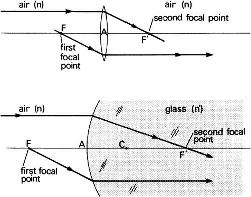 Fig. 5. Positions of the first and second focal points formed by a positive thin lens in air and positive single refracting surface. The distance from F to A is equal to the distance A to F′ for the thin lens. The distance F to A is equal to the distance from C (the center of curvature) to F′ for a single refracting surface. |
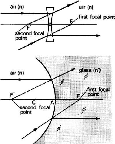 Fig. 6. Positions of the first and second focal points formed by a negative thin lens in air and a negative single refracting surface. |
Vergence
Light diverging from the object point in Figure 7 has negative vergence. The spherical wavefronts grow larger as their radial distances from the source increase. Because curvature is the reciprocal of the radius of curvature, the farther the wavefront is from the object, the smaller its curvature will be. Wavefront vergence in diopters equals the reciprocal of the radial distance in meters:
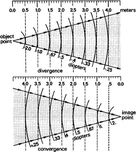 Fig. 7. Vergence in diopters shown in relation to a distance scale in meters. Light from the object point diverges; light converges toward the image point. The farther the wavefronts are from either of these points, the shallower their curvatures and the weaker the dioptric values of their vergences. |
Light that is converging toward an image has positive vergence. The wavefronts become increasingly curved as they approach the image point, and the vergence increases correspondingly. For example, at a distance of 4 m, the vergence is + 0.25 D; at 2 m, the vergence is + 0.5 D. Diopters of convergence (+) and divergence (-) for various distances from object and image are tabulated as shown in Table 1. It is assumed that light travels from left to right. Consequently, a divergent wavefront is centered about a point to the left of the wavefront. Because the wavefront is negative, the distance from the wavefront to the point (which may be a real object or a virtual image point) is negative. Convergent wavefronts are centered about real images or virtual objects to the right of the wavefront. These distances are positive.
TABLE 1. Vergences in Diopters at Various Distances | ||||||||||||||||||||
|---|---|---|---|---|---|---|---|---|---|---|---|---|---|---|---|---|---|---|---|---|
|
Reduced Vergence
Objects and images in media of any refractive index have reduced distances. For objects, the reduced distance is ℓ/n, the reduced image distance is ℓ′/n′. Similarly, the reduced first focal length is f/n and the reduced second focal length is f′/n′. Just as vergence is the reciprocal of the distance, reduced vergence is the reciprocal of the reduced distance. L = n/ℓ is the reduced vergence of the object; the reduced vergence of the image is L′ = n′/ℓ′.
Optical elements have the power to impress a vergence on incident light. The refracting power F (not to be confused with the first focal point F) is equal to the reciprocal of the reduced focal length (i.e., F = n/f = n′/f′). The reduced vergences of the object and image and the refracting power are related in a very simple equation:
The reduced vergence of the light after refraction (heading toward the image point) is the sum of the reduced vergence of the light from the object when it is incident on the lens or refracting surface plus the power of the lens or surface. For example, an object in air placed 2 m to the left of a lens will send light to the lens that, when it reaches the lens, has a divergence in diopters
If the lens is a positive lens with a focal length of 0.50 m, the lens power
The image vergence becomes L′ = -0.50 + 2.00 = + 1.50 D.
This shows that the light leaves the lens with a convergence L′ of 1.50 D and will be imaged in air at
The positive sign means the image is real and to the right of the lens (Fig. 8). Both the object and image lie in air. They will lie in different media if the lens is replaced by a single refracting surface. For example, it may be supposed that a convex refracting surface of radius 0.25 m separating water and glass is facing an object 3 m away (Fig. 9). The object is found in water for which n = 1.33. Consequently, the reduced object vergence
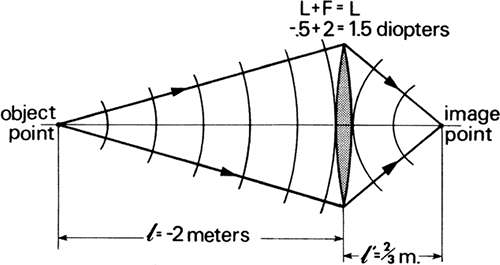 Fig. 8. Illustration of the vergence equation L’ = L + F for a thin lens. |
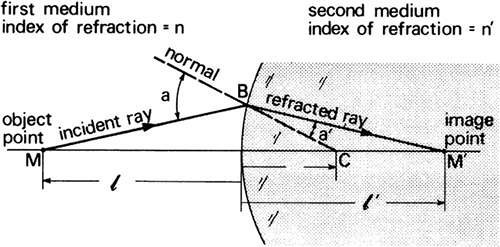 Fig. 9. Illustration of the vergence of equation L′ = L + F for a single refracting surface separating water (n = 1.33) from glass (n′ = 1.5). (Drawing is not to scale.) |
The refracting power of a single refracting surface is the difference between the second and first indices of refraction divided by the radius of curvature in meters:
Because n′ = 1.50, n = 1.33, and r = + 0.25 m,
The reduced vergence of the refracted light is L′ = L + F = –0.44 + 0.68 = +0.24 D.
By rearranging the equation L′ = n′/ ℓ′ to give ℓ′ = n′/L′ = 1.50/0.24 = 6.25 m, we obtain the position of the image. It is real and located 6.25 m in glass to the right of the refracting surface.
Magnification
In Figure 10, an object whose height is y is a distance ℓ from a thin positive lens. The lens forms an inverted image at ℓ′ with a height of y′. Lateral magnification (m) is the ratio of the image height divided by the object height, m = y′/y. It can also be shown that magnification is equal to the reduced vergence from the object divided by the reduced vergence to the image: m = L/L′.
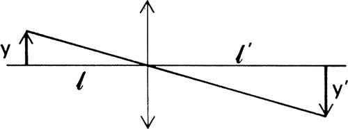 Fig. 10. Lateral magnification of an object with height y at distance 1 from a thin lens. |
In the previous lens example, we found L = -0.50 D, and L′ = +1.50 D; consequently, the magnification is m = L/L′ = -0.50/150 = -0.33. The image is one-third as large as the object and the minus sign means that the image is inverted.
Similarly, in the previous example of a refracting surface separating water and glass, L = -0.44 D and L′ = 0.24 D. The magnification is m = -0.44/0.24 = -1.83.
Principal Points
The paraxial characteristics of a complex optical system, such as the series of lens elements shown in Figure 11a, can readily be determined by reducing the system to six cardinal points. Two of these points, the first and second focal points, have been considered already. Another pair, known as the first and second principal points, will now be defined.
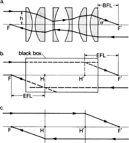 Fig. 11. Principal planes of a complex lens system, a. Paths of paraxial rays from infinity to F′ and F. b. Lens system is replaced by a black box in which two planes, found by the intersection of the projections of the incident and emergent rays, are located. c. Lens system is replaced by the principal planes. |
Suppose an incident paraxial ray from infinity strikes the first lens element at a height h above the axis and is refracted through the lens system. When it strikes positive elements, it is bent toward the axis. Negative elements bend it away from the axis. Ultimately, it emerges from the last element at a height h′ above the axis and with a slope that converges it to the second focal point F′. Because this lens system consists of several spaced-out elements, it cannot be treated like a thin lens. Consequently, the distance from the last element to F′ is not equal to the focal length of the system; it is called the back focal length (BFL) and is of physical rather than optical significance. The focal length of optical significance is the equivalent focal length (EFL). This term implies that the lens system has a focal length that is equivalent to that of a simple “thin” lens. To find the position of this hypothetical thin lens with respect to focal point F′, the series of lenses is replaced by a black box (Fig. 11b). What is in the black box is unimportant once the height of incidence h, the height of emergence h′, and the slope θ′ toward the focal point of a paraxial incident ray are known. The second principal plane is located by extending the incident ray forward and the emerging ray backward until they intersect. This plane defines the position of a thin lens that could theoretically replace the lens system. The point H′ where this plane crosses the axis is called the second principal point. The distance from F′ to H′ is the equivalent focal length of the complex lens.
If this process is repeated for a paraxial ray from infinity entering the lens system (or black box) from right to left, H, the first principal point, is obtained. The distance from F to H is the same as F′ to H′ (i.e., the equivalent focal length is constant no matter how the lens is turned. Usually, H and H′ do not coincide. Any ray incident at some height at the first principal plane is transferred to the second principal plane at the same height as if the two planes were coincident. Consequently, the principal planes are considered conjugate planes with a magnification of one, or unit magnification planes (Fig. 11c). No real thin lens can replace a complex system. Principal planes merely simplify calculating such paraxial quantities as object and image position and magnifications.
Nodal Points
The remaining two cardinal points are a pair of axial points called the nodal points. They are extremely useful in calculating image sizes. An incident ray directed toward the first nodal point will appear to emerge from the second nodal point with unchanged direction. Therefore, the nodal points are called points of unit angular magnification.
When both the object and image lie in a medium of the same index of refraction, the first and second nodal points coincide with the first and second principal points (Fig. 12c). If the lens is a simple thin lens in a uniform medium the principal and nodal points all coincide at the vertex of the lens (Fig. 12a). If the image is not in the same medium as the object, as in the single refracting surface of Figure 12b, the nodal points do not coincide with the principal points. The two principal points coincide at the vertex of the surface, and the two nodal points coincide at the center of curvature of the surface. For all these cases, the slope of the ray directed toward the first nodal point is the same as the slope of the ray that appears to emerge from the second nodal point.
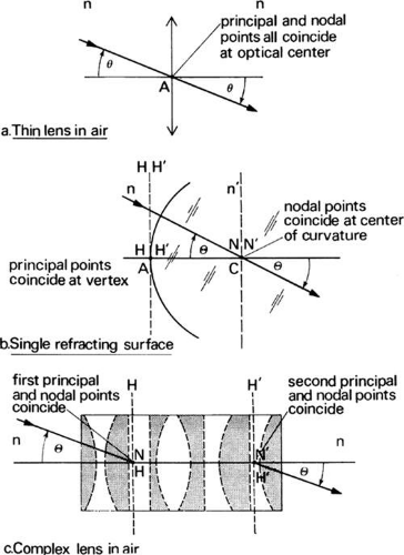 Fig. 12. The relationship between principal and nodal points. a. Thin lens: H, H′, N and N′ coincide at the optical center. b. Single refracting surface: H and H′ coincide at the vertex; N and N′ coincide at the center of curvature. c. Complex lens in uniform medium: H and N coincide; H and N′ coincide. |
The eye is a complex series of refracting surfaces that forms an image in vitreous of an object in air. Therefore, it has a pair of principal planes and a separate pair of nodal points that can be used to represent it. Their positions are shown in Gullstrand’s schematic eye (see Fig. 110).
Thick Lens Equation
The equivalent refracting power of a thick lens or two separated optical elements is given by Gullstrand’s equation:
F = F1 + F2 – cF1 F2
where F1 is the refracting power of the first element, F2 is the power of the second element, and c = d/n is the reduced distance separating the two elements.
This equation will prove useful when the combined power of the eye and a spectacle lens is considered. The dioptric power of the spectacle lens will be F1 and the dioptric power of the eye will be F2. The distance from the eye at which the spectacle lens is fitted is d/n = 1 because the medium between the lens and the eye is air.
Refractive State of the Eye
The image of an infinitely distant object will fall in front of the retina in myopia, on the retina in emmetropia, and behind the retina in hyperopia, when these eyes are exerting zero accommodation. Because the image of an infinitely distant object defines the position of the second focal point of any optical system, the previous sentence can be restated to say that the refractive state of the eye depends on the second focal length. The eye is myopic when the second focal length is shorter than the length of the eye, it is emmetropic when the two lengths are equal, and it is hyperopic when the second focal length is greater than the length of the eye. Twenty feet (6 m) is the clinical equivalent of infinity. This introduces a vergence of -1/6 D at the eyes that we ordinarily neglect.
Classification of refractive states into categories of hyperopia, emmetropia, and myopia should not obscure that they represent a continuum of eye growth and changes. Except that a hyperope requires a plus lens and a myope a minus lens correction, the two eyes are physiologically alike and optically differ only as far as the position of the second focal point is on one or the other side of the retina. As the eyeball grows, some flattening of the cornea and lens offsets the refractive error that otherwise would result. This process of emmetropization tends to restrain the development of high refractive errors and concentrates the distribution of refractive states near emmetropia.
Emmetropia
Although the emmetropic eye, with relaxed accommodation, forms sharp retinal images of distant objects, emmetropia is not the statistically normal refractive state. Studies of refractive state show that the peak of the distribution curve occurs at approximately 1 D of hyperopia, although the frequency of myopia is greater in adults than in children (Fig. 13). Most infants are hyperopic, probably because the axial length of their eyeballs is too short. Consequently, hyperopia decreases with growth. Emmetropia is considered merely a point on the curve of refractive status that marks the transition from hyperopia to myopia. It occurs when the length of the eyeball, the curvature of the cornea, and the power of the unaccommodated lens are all appropriate for focusing collimated light on the retina, a remarkable condition to exist in so large a sample of the population. The young emmetrope with normal amplitude of accommodation will have distinct distant and near vision, assuming there are no problems with binocular vision or amblyopia.
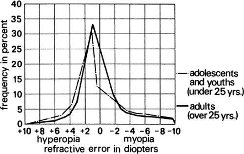 Fig. 13. Distribution of refractive errors among the population (Wulfeck JW et al: Vision in Military Aviation. WADC Technical Report 58–399. Wright Air Development Center, OH, Nov 1959.) |
In subsequent sections, a 58-D reduced eye model is used, that is, an eye with a single refracting surface that separates air from aqueous humor with an index of refraction of 1.333. The radius of curvature this eye equals 333/58 = 5.74 mm, its first focal length = 1000/58 = 17.2 mm, and its length or second focal length = 1333/58 = 23.0 mm
Ametropia
Ametropia exists when distant objects are not sharply focused on the retina by an eye with relaxed accommodation. The eye is too long or too short for its power or too weak or too strong for its length. Whether it is power or length (i.e., refractive or axial ametropia) depends on establishing norms for power and length as, for example, those of Gullstrand’s schematic eye. Naturally, any given individual may have both axial and refractive ametropia. In the interest of simplicity the two types will be considered separately.
Far-point
Because the emmetrope forms an image of an infinitely distant object on the retina, the retina is conjugate with infinity. That is, if the light paths are reversed and the retina is considered an object, then the image of the retina, formed by the emmetropic eye, would lie at infinity. The point in space conjugate to the fovea is called the far-point. It is the farthest point of distinct vision. Figure 14a illustrates that in emmetropia the second focal point falls on the retina, therefore, the far-point is at infinity.
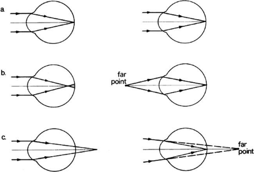 Fig. 14. a. Emmetropia: an infinitely distant object is focused on the retina; the far point is at infinity. b. Myopia: an infinitely distant object is focused in front of the retina; the far point is a finite distance in front of the eye. c. Hyperopia: an infinitely distant object is focused behind the retina; the far point is a finite distance behind the eye. |
To find the far-point of a myopic eye, it must be remembered that this eye is too strong. As a result, collimated rays focus short of the retina, and the second focal point lies within the vitreous (Fig. 14b). To compensate for this excessive power of the eye, the object must be brought closer. A closer object sends divergent light to the eye that pushes the focus closer to the retina. When divergence just matches the amount of excessive power of the eye, the image falls on the retina, and the object is at the far-point of the eye because it is conjugate with the retina. For example, if an object must be brought to within 1 m of the eye for its image to fall on the retina, the far-point is at 1 m and the eye suffers from 1 D of myopia. A myopic eye always has a far-point at some real distance in front of the eye.
The location of the far-point for the hyperope is precisely the opposite (i.e., it is a virtual point behind the eye) (Fig. 14c). Because the hyperopic eye has inadequate refractive power, collimated light will appear to focus behind the retina. Of course, the light is intercepted by the retina, so it does not actually focus behind the retina. Any object now in front of the hyperopic eye, if brought toward the eye, will provide divergent light. The hyperopic eye is weak, however, so the image will fall even further behind the retina. Unaccommodated hyperopes will not see clearly at any distance in front of them. To move the image from behind the retina onto the retina, the light must be convergent when it strikes the eye or appear to focus behind the eye. Obviously, real objects cannot be seen behind the retina, so a plus lens in front of the eye is needed to achieve this convergence. If a plus lens provides, for example, 1 D of convergence at the eye, the lens will form an image of a distant object 1 m behind the eye. This image appears to be a virtual object to the eye. If the unaccommodated hyperope’s eye can focus this image on the retina, the far-point of the eye is 1 m behind the eye (i.e., the retina is conjugate with the virtual object); the eye has 1 D of hyperopia.
Length of Eye in Axial Ametropia
The length of the eye is the distance from V to F′ (VF′). It comprised the distance from the vertex V to the second principal point H′ (VH′) plus the distance ℓ′ from H′ to the second focal point F′ (H′F′ = ℓ′). F′ is coincident with the retina. In axial ametropia, the position of the focal point F′ varies; however, H′ is nearly fixed in position at 1.6 mm from V, regardless of the ametropia (see Fig. 15). Consequently, the length of the eye will be 1.6 + ℓ′. Length is obtained with the fundamental equation: L′ = L + F where, in axial ametropia F is constant (58.64 D), L is the vergence at the eye owing to an object at the far-point, and L′ will be the vergence after refraction. Figure 16 presents the calculated length of the schematic eye in axial ametropia.
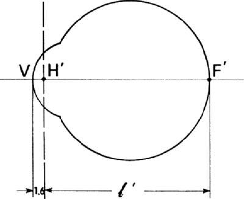 Fig. 15. The length of the schematic eye is calculated with respect to the second principal plane, which lies 1.6 mm behind the cornea. |
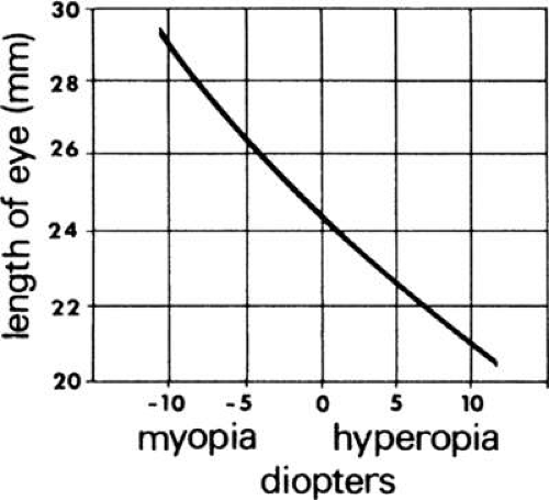 Fig. 16. Variation in the length of the schematic eye in axialametropia. |
Correction of Myopia
The far-point of a myopic eye lies in front of the eye. The relaxed myopic eye can distinctly see this point, but no farther. To enable the myopic eye distinctly to see infinitely distant objects, it is necessary to make these objects appear to be at the far-point by altering the vergence of the light from infinity so that it enters the eye with the same divergence as rays from the far-point. This requires a lens at the eye that will diverge collimated light so that it appears to come from the far-point. Such a lens is a minus lens and if collimated light strikes this lens it will appear to be focused at the second focal point of the lens. Consequently, a minus lens whose second focal point is coincident with the far-point of the myopic eye will correct that eye. It will cause collimated rays from infinity to enter the eye with the same divergence as rays from the far-point, and be focused on the retina. This is illustrated in Figure 17. The uppermost diagram depicts a myopic eye sharply focusing light from its far-point on the retina. Light from points beyond the far-point would have less divergence at this eye and be focused in front of the retina. The action of a properly chosen minus lens is shown in the middle diagram. This lens causes light from infinity to diverge so that, on emerging, the rays appear to originate at a virtual image point coincident with the far-point. If the lens is now combined with the eye as shown in the bottom diagram, the necessary divergence to light from infinity has been provided to enable the eye to focus the rays on the retina. The combination of minus correction lens and eye system causes the retina to be conjugate with infinity, thus corresponding to the condition of emmetropia.
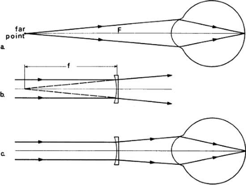 Fig. 17. Spectacle correction of myopia. a. Rays from the far point are focused on the retina. b. A negative lens whose second focal point coincides with the far point forms a virtual image of rays from infinity at the far point. c. Rays from the infinity strike the eye with a vergence as if from the far point and are focused on the retina. |
Correction lenses are worn close to the eyes for several very important reasons. First, frames supported by the nose and temples are extremely convenient devices for fitting the lenses in front of the eyes. The resultant closeness of the lenses to the eyes provides large fields of view with small diameter lenses. Furthermore, the position of the correction lens mounted in a frame is very near the first focal point of the eye (approximately 15 mm); as a result, the size of the retinal image of the corrected ametrope is practically the same as the emmetropic image size. The correction lens introduces minimal magnification or demagnification of the retinal image when worn near the anterior focal point of the eye, which is approximately where a frame places the lens.
This position for the correction lens is only one of many possible positions at which the correction lens can be placed to produce sharp retinal images. Whatever position is chosen, the second focal point of the correction lens must coincide with the far-point of the eye. The closer to the far-point the lens is placed, the shorter must be its focal length. This, in turn, will reduce the size of the image on the myopic retina.
Correction of Hyperopia
The far-point of the hyperopic eye lies behind the retina. Without accommodation, unaccommodated hyperopes cannot see distinctly any point in front of them from near to infinity. Light must strike the eye with convergence, that is, appear to come from the virtual object (far-point) behind the retina, if it is to be focused on the retina. A hyperope can converge the light by accommodating—seeing clearly at far—but the eye is in a relaxed state of accommodation. Consequently, to see clearly at far, a plus lens is needed that has a second focal point coincident with the far-point of the eye; thus, the image of a distant object is moved to the retina. The combination of correction lens and eye causes the retina to be conjugate with infinity as it would be in emmetropia. The closer this lens is to the eye, the shorter must be its focal length if F′ is to be coincident with the far-point. Just as in the myopic correction, the magnification depends on the position and power of the lens.
Figure 18 illustrates how a plus lens corrects the hyperopic eye. The top diagram shows how the eye can focus on the retina rays that were initially converging toward its far-point behind the retina. The middle diagram shows a plus lens positioned to make its second focal point coincide with the far-point. The lens converges rays from infinity toward the far-point; consequently, when these rays strike the eye, as in the bottom diagram, the eye can focus them on the retina.
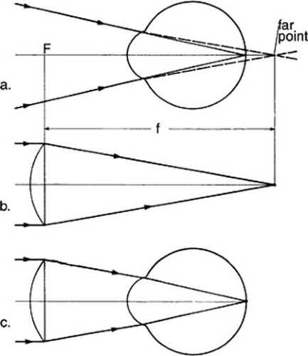 Fig. 18. Spectacle correction of hyperopia. a. The far point lies behind the eye. Rays converging to the far point lie behind the eye. Rays converging to the far point are focused on the retina. b. A positive lens focuses rays from infinity at its second focal point, which is coincient with the far point. c. Convergent rays strike the eye and are focused on the retina. |
Astigmatism
Paraxial theory indicates that spherical refracting surfaces form point images because these surfaces have constant curvatures in all meridians. Cylinders, conversely, have a maximum curvature along their circumferential direction and zero curvature along their length, that is, parallel to the cylinder axis. The zero curvature is 90 degrees to the maximum curvature. A cylindrical refracting surface will form a line image of a point parallel to the cylinder axis. If the cylinder is bent into a doughnut shape, then the meridian that formerly had zero curvature takes on a curvature. This curvature is less than the circumferential curvature and is at 90 degrees to the latter. Thus, a toric surface results, which forms two line images of a point at right angles to each other and at different distances along the axis. The distance between these line foci is called the interval of Sturm in honor of the mathematician who investigated it in 1838. The interval of Sturm is shown in Figure 19 as formed by a toroidal lens that is curved more deeply vertically than horizontally, with a circular aperture. The bundle of light, as it traverses the interval of Sturm, has its cross-section transformed from a horizontal line to a horizontal ellipse. Then it becomes circular in section, and this position is known as the circle of least confusion. As the light progresses, the section becomes elongated into a vertical ellipse. This narrows to a vertical line at the end of the interval. The eye becomes astigmatic when any of its refracting surfaces assume a toroidal shape. The astigmatism is termed regular if the meridians of maximum and minimum curvature are at right angles to each other. These meridians are called principal meridians.
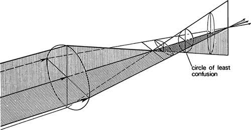 Fig. 19. Formation of the circle of least confusion by a toroidal lens. |
With- and Against-the-Rule Astigmatism
Astigmatism of the eye can be hyperopic or myopic, depending on whether the astigmatic foci fall behind or in front of the retina. Corneal astigmatism is most pronounced, although lenticular astigmatism often is manifested when a spherical contact lens eliminates the toricity of the cornea. The condition in which the meridian of greatest power is vertical, or within 30 degrees of the vertical, is most common and it is called with-the-rule astigmatism. It is corrected with a minus cylinder at axis 180 degrees. When the corneal curvature of greatest power is horizontal ± 30 degrees, it is called against-the-rule astigmatism. In the following classification, accommodation is inactive and the object point is very distant.
Simple Hyperopic Astigmatism
In simple hyperopic astigmatism, the meridian of maximum power is emmetropic, therefore, it forms a line image of a point on the retina. If that meridian is at 90 degrees, the astigmatism is with-the-rule, and a horizontal line is focused on the retina. The meridian of minimum power is hyperopic. It will form a vertical line image behind the retina. The interval of Sturm extends from the retina to this image behind it (Fig. 20a). Suppose an individual has 1 D of against-the-rule corneal astigmatism: Using the reduced eye as a model, the power in the 180 degree meridian is 58 D. The power in the 90 degree meridian is 57 D because the hyperopic astigmatism is refractive in nature. The positions of the line images with respect to the principal point P of the reduced eye are:
Vertical line image: f =1336/58 = 23.0 mm; horizontal line image: f = 1336/57 = 23.4 mm. The interval of Sturm is 23.4 mm – 23.0 mm = 0.4 mm.
Correction will be obtained with a +1.00 DC axis 180 degrees or with +1.00 – 1.00 axis 90 degrees.
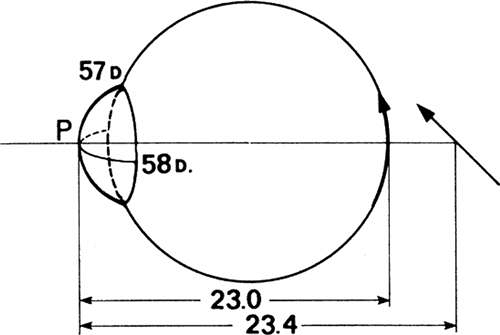 Fig. 20a. Simple hyperopic against-the-rule astigmatism. |
Compound Hyperopic Astigmatism
Both the maximum and minimum meridional powers are refractively hyperopic in compound hyperopic astigmatism. In Figure 20b, the meridian of maximum power (57 D) is at 90 degrees. This is with-the-rule astigmatism, and this meridian forms a horizontal line image at distance of 23.4 mm. The more hyperopic (weaker) meridian at 180 degrees has a power of 56 D in this example.
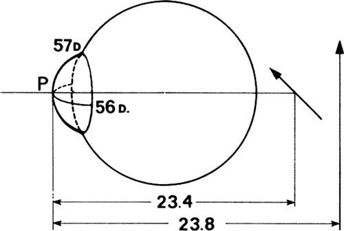 Fig. 20b. Compound hyperopic with-the-rule astigmatism. |
It forms a vertical line image along the 90-degree meridian, at a focal distance f = 1,336/56 = 23.8 mm. The interval of Sturm is 23.8 – 23.4 = 0.4 mm, calculated in vitreous, but it would extend from 0.4 to 0.8 mm behind the retina. Although accommodation will allow the movement of the line foci toward the retina, both line foci cannot be simultaneously placed on the retina. Accommodation here is an attempt to find the best compromise focus which is usually the circle of least confusion.
A + 1.00 + 1.00 × 90° lens or +2.00 – 1.00 × 180° lens will correct this eye.
Simple Myopic Astigmatism
In simple myopic astigmatism, the eye is emmetropic in one meridian. A distant point will be imaged as a line on the retina by the power in this meridian. Figure 21 illustrates simple myopic with-the-rule astigmatism. The power in the 90-degree meridian is 59 D or myopic by 1 D. The power in the 180-degree meridian is a normal 58 D. The image conjugates with respect to the principal point of the reduced eye are:
Horizontal line image: f = 1336/59 = 22.64 mm; vertical line image: f = 1336/58 = 23.0 mm. The interval of Sturm is 22.64 – 23.0 = 0.36 mm. A minus 1-D cylindrical lens axis 180 degrees will correct this condition.
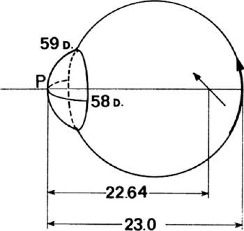 Fig. 21. Simple myopic with-the-rule astigmatism. |
Compound Myopic Astigmatism
Compound myopic astigmatism occurs when the meridians of maximal and minimal are both too strong (i.e., refractively myopic). Both line images fall short of the retina, and the interval of Sturm is displaced forward of the retina, within the vitreous. In Figure 22, the meridian of greatest power is horizontal, therefore, the astigmatism is against-the-rule. The interval of Sturm is 22.27 – 22.64 = -0.37 mm. The myope is unable to shift the circle of least confusion back to the retina. A minus sphere combined with a minus cylinder will bring both foci to a common point on the retina.
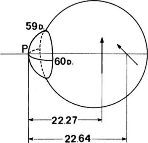 Fig. 22. Compound myopic against-the-rule astigmatism. |
Mixed Astigmatism
As the name implies, mixed astigmatism has a myopic and a hyperopic component. The meridian of weakest power forms a line conjugate to a distant point behind the retina, whereas the meridian of greatest power produces a line image within the vitreous humor. Thus, the interval of Sturm straddles the retina. In Figure 23 the vertical meridian is hyperopic. The meridian of greatest power is horizontal, therefore, the astigmatism is against-the-rule. The interval of Sturm is 0.43 + 0.36 = 0.79 mm.
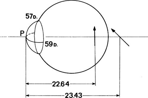 Fig. 23. Mixed against-the-rule astigmatism. |
Irregular Astigmatism
In the previous examples of types of regular astigmatism, the axes were at 90 degrees and 180 degrees. In actuality, the axes can be at any meridian. If the maximal and minimal curvatures are 90 degrees apart, the astigmatism is regular; for example, 45 degrees and 135 degrees, or 65 degrees and 155 degrees If, however, the two principal meridians of curvature are not 90 degrees apart or the corneal curvature is not axially symmetric, the condition is irregular astigmatism. This may result from injury, corneal diseases that leave scars, keratoconus, or congenital abnormalities. Because spectacle lenses necessarily are ground to uniform curves, they cannot properly correct axial asymmetries of the cornea. If grinding an asymmetric correcting lens were possible, it would be proper only for a fixed eye position because the mobile eye would view through different portions of the lens that would vary in power. The ideal solution to irregular corneas and irregular corneal astigmatism is to use contact lenses that replace the cornea with a regular refracting surface and move with the eye so that they are always centered.
Accommodation
Normally, a person can sharply see distant scenes and objects held close to the eye without awareness of any focusing by the eye. As a result, the noncritical observer assumes that all distances are simultaneously in focus for the eye. Scheiner showed with his two-hole disc that, in fact, when a distant scene is sharply seen, a fine pin held close to the eyes appears double. Similarly, if the eye is focused on the pin, a distant scene appears double. As seen in Figure 24, the two pinholes transmit two small bundles of the rays that otherwise would enter the eye and come to a focus. If this focus falls on the retina, the two bundles converge to one point and the observer perceives one point. If the focus falls in front or behind the retina, the two bundles intersect the retina at two separate points and a double image is perceived. Scheiner used this to measure the accommodation of the eye. Simply stated, a fine distant object was brought closer to the eye. As long as the eye accommodated, it maintained the object in focus and it was perceived singly. Accommodation was exerted maximally when the object had reached the near-point. Further approach caused the object to appear double. The point at which doubling is first perceived is called the near-point of accommodation.
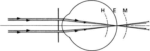 Fig. 24. Scheiner’s disc experiment. |
The sequential occlusion of the two holes of the Scheiner disc can be used to find the refractive state of the eye. For example, the pencil of rays through the lower hole will strike the hyperopic retina below the axis and the myopic retina above the axis. The hyperope will note a disappearance of the upper image (opposite), and the myope will not see the lower image (same) when the lower hole is occluded. (Hint: project the retinal point back through the nodal point for the apparent direction of the same source.)
Thomas Young (1773–1829) pioneered the investigation of the accommodative mechanism of the eye. Theoretically, the eye can change its focus in several ways. It can change its axial length. This is essentially how a camera is focused for near objects. The lens simply is moved farther from the film plane by means of a focusing ring built into the lens barrel or, in extreme close-up work, the lens is attached to a bellows that permits positioning the lens through a much greater range. A natural question, then, is whether the eye elongates to focus on near objects. A young emmetrope can focus easily on an object 10 cm from the eye. The elongation of the eye required to place the retina in the image plane of this object can be found with the vergence equation. The eye must elongate to 27.7 mm. When the object is at infinity, the position of the image is shown to be 22.9 mm, thus, the growth in axial length of the eyeball is 27.7 – 22.9 = 4.8 mm. This is a change in axial length of >20% of the emmetropic length of the eye, and it must be accomplished almost instantly, imperceptibly, and unflaggingly during the waking hours. Clearly, the human eye does not accommodate in this manner.
Accommodation also can be mediated through an increase in the power of its refractive elements. The eye theoretically can increase its power through a shortening of the radius of curvature of the cornea or the lens or by an axial shift of the lens. Young, in an experiment, immersed his eyes in water. By nearly matching the refractive indices at the water–cornea interface, he practically eliminated the corneal refractive power. He became an extreme refractive hyperope. To see distant objects clearly, Young introduced a positive lens to replace the lost corneal power and could accommodate for near objects. Thus, he showed that accommodation could be exerted despite the neutralization of the cornea. Although the crystalline lens remained the most logical agent of accommodation, the question to be resolved was whether the crystalline lens moved axially or changed shape. Axial movement was eliminated by the constraints on how much the lens could move within the anterior chamber. Calculations show that the depth of the anterior chamber is not sufficient for maintaining the focus of near objects.
The steepening curvatures of the crystalline lens account for the ability to accommodate. Helmholtz concluded that the zonule maintains shallow lens curvatures in the unaccommodated state. Relaxation of the fibers, when the ciliary body constricts, allows the elastic capsule of the lens to assume a rounder form. Tscherning noted that the central portion of the lens became more deeply curved, whereas the peripheral zone of the lens surface flattened during accommodation. He concluded that this occurred because of an increase in tension by the zonule during accommodation. Generally accepted is that Helmholtz is correct in concluding that relaxation of tension by the zonule allows the lens to assume a more deeply curved form. Fincham concluded that it was the nonuniform thickness of the lens capsule that caused the bulge in lens curvatures in accommodation rather than capsule elasticity.23
Gullstrand provides a radius of curvature of 10 mm for the anterior surface of the crystalline lens when relaxed and a radius of curvature of 5.33 mm when accommodated by nearly 10 D. The axial thickness of the lens slightly increases because of the forward bulge of the anterior surface. Mainly because of the bulge, the power of the lens increases from 19 to 33 D, and the power of the eye correspondingly increases from 58.64 to 70.57 D.
Amplitude and Range of Accommodation
When the eye is accommodated fully, the point in space conjugate to the retina is the near-point of the eye. It is the nearest point of distinct vision. How much accommodation is exerted from the relaxed state to full accommodation is termed the amplitude of accommodation. If the distances of the far- and near-points from the first principal point of the eye are denoted by r and p and the corresponding reduced vergences are denoted by R and P, the difference R – P = A, in diopters, is the amplitude of accommodation. The corresponding distance of distinct vision from the near-point to the far-point of (p – r) = a, is termed the range of accommodation (Fig. 25). The range of accommodation for a given amplitude of accommodation depends on the refractive state of the eye (Table 2). An emmetrope, a myope, and a hyperope may each have the same amplitude of accommodation, but their ranges of accommodation will differ greatly. To find the range of accommodation requires knowing the amount of ametropia and the amplitude of accommodation. From these, the far- and near-points can be calculated. The range of accommodation is the distance between these points. For example, of three individuals, each with an amplitude of accommodation of A = 10 D, one is an emmetrope, the second is a 5-D hyperope, and the third is a 5-D myope. What are their ranges of accommodation?
 Fig. 25. Range of accommodation in myopia (top) and hyperopia. |
TABLE 2. Range of Accommodation for a Given Amplitude | |||||||||||||||||||||||||||||||||||||||||||||
|---|---|---|---|---|---|---|---|---|---|---|---|---|---|---|---|---|---|---|---|---|---|---|---|---|---|---|---|---|---|---|---|---|---|---|---|---|---|---|---|---|---|---|---|---|---|
|
The emmetrope’s far-point r is at infinity, therefore, R = 1/∞ = 0. Substitution into the equation R – P = A, results in 10 = 0 – P, or the dioptric value of the near-point is P = -10 D. This corresponds to a near-point distance p = 1/P, or p = -0.10 m = -10 cm. The emmetrope’s range of accommodation is from 10 cm in front of the first principal plane of the eye to infinity. The hyperope has a far-point R = + 5 D, that is, the far-point distance r is 0.20 m behind the eye. P = R – A = 5 – 10 = -5 D. The near-point distance p is 0.20 m in front of the eye. In effect, 5 D of accommodation was exerted to overcome the hyperopia, to see sharply at infinity, and the remaining 5 D determined the near-point. The range of accommodation of the hyperope is from 20 cm in front of the eye, through infinity, to 20 cm behind the eyes.
The dioptric value of the far-point of the 5-D myope is R = -5. Thus, P = -5 – 10 = -15 D. The range of accommodation of the myope is A = P – R = -100/15 + 100/5 = -6.7 + 20 = + 13.3 cm, or from 6.7 cm to 20 cm in front of the eyes.
These examples illustrate the limited range of accommodation available to the myope who otherwise has an amplitude of accommodation equal to that of an emmetrope and hyperope.
Presbyopia
The amplitude of accommodation decreases from childhood to 75 years of age. When the reduction in amplitude causes the near-point to move beyond the comfortable reading distance, the condition is termed presbyopia. Presbyopia has its onset at about 45 years of age when, according to Donders, the amplitude of accommodation is 3.5 D. A 45-year-old individual who is emmetropic, will have a near-point of R – P = 3.5 D. Therefore, p = 100/3.5 = 28.5 cm = 11 inches. At 55 years of age, this individual’s amplitude has dropped to 1.75 D with a near-point of p = 100/1.75 = 57 cm = 22.5 inches. Ten years later, at 65 years of age, this individual has only 0.5 D of amplitude with a near-point now of p = 100/0.5 = 200 cm = 80 inches. Finally, at 75 years of age, this individual has zero amplitude, a near-point and far-point at infinity, with a range of accommodation also at zero. Because of a depth of focus of ¼D, this person still can see clearly from 4 m out to infinity.
The relationship between amplitude of accommodation and age, which was investigated by Donders, for a long time was used as a basis for prescribing a near add. Measurements of monocular amplitude of accommodation were made on 4,000 eyes by Duane. The results, shown as an average middle curve and upper and lower ranges on amplitude at any given age, are plotted in Figure 26 and listed in Table 2. Various causes have been proposed to account for the reduction in accommodative amplitude. Accommodation has two parts. One is physical and concerns the change in shape of the lens during accommodation. In presbyopia, the physical part is related to hardening or sclerosis of the crystalline lens that reduces the elasticity of the lens capsule and the plasticity of the lens core. The physiologic part of accommodation is the innervation and contraction of the ciliary muscles. Some believe that sclerosis of the ciliary body reduces its ability to constrict, and the lens does not sufficiently obtain the conditions required for changing its shape. If most of the cause of presbyopia is physical, that is, it is related to the inability of the crystalline lens to alter its shape to bring near objects into focus, then the lens is an indicator of age and may be considered a biological clock.
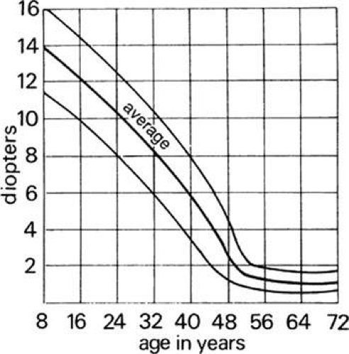 Fig. 26. Monocular amplitude of accommodation with age for 4000 individuals. (Southall JPC: Introduction to Physiological Optics, p 89. New York: Dover, 1937.) |
Retinal Image Size
The size of the retinal image is easily found by using the reduced eye model. The reduced eye considered there consists of a single spherical refracting surface with a radius of curvature of 5.6 mm that separates air from vitreous humor with an index of refraction of 1.336 at 587.6 nm (Fig. 106). The is 22.27 mm long and has a power of 60 D. Several rays may be used, but the simplest ray to use is the undeviated one through the nodal point to the retina. For example, in Figure 27, this ray comes from the tip of a distant tree which subtends an angle θ = 0.1 radians at the nodal point N. The retinal image subtends the same angle at the nodal point. Thus, Y′ = 17.2 × 0.01 = 1.72 mm.
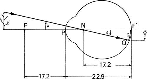 Fig. 27. Retinal image size constructed by means of a ray through the nodal point. |
Image point Q′ can be constructed with rays other than the one through the nodal point. In Figure 28, two rays from an infinitely distant object that subtends an angle θ at the eye are incident on the eye. The rays are parallel to each other (collimated). The upper ray is headed toward the nodal point and is identical to the ray previously discussed. It strikes the retina at a height Y′ = 17.2 × θ. The lower ray crosses the axis at the first focal point F. When this ray strikes the eye, it appears to originate at the first focal point and travels parallel to the axis after refraction. Because it travels parallel to the axis after entering the eye, its height remains constant from the point of incidence T, at the refracting surface, to the retina. In the figure, triangle FPT is the same as triangle NF′Q′ because both triangles have identical angles θ and sides that are 17.2 mm long. Consequently, height PT must equal height F′Q′ and so the lower ray will strike the retina at point Q′ just as did the ray through the nodal point. The triangles can be visualized better by assuming a flat cornea and retina that are the conditions for paraxial calculations; that is, the rays are assumed to strike these surfaces so close to the axis that the surfaces are practically flat over this short distance from the axis.
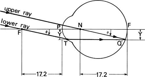 Fig. 28. Construction of image at intersection of ray through nodal point with ray through first focal point of the eye. |
Image Size in Ametropia
Emmetropia prevails when the refractive power and axial length of the eye are properly matched. Clearly, any number of combinations of power and length will produce emmetropia. Figure 29 illustrates the variation of axial length with ametropia. It is evident in that for any given angular subtense of the object at the nodal point of the eye, the retinal image will be smallest in hyperopia and largest in myopia. The image size will be in direct proportion to the length of the eye.
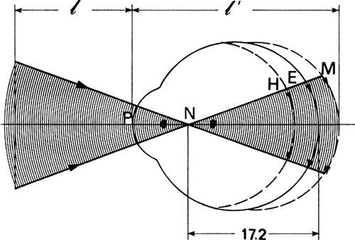 Fig. 29. Visual angle and retinal image size in ametropia. The size of the retinal image corresponding to a given angular field of view (θ) varies with the elongation of the eye. |
Image Size of Object at Far-point in Axial Myopia
To form a sharp image on the retina of an axial myope, a distant object must be brought toward the eye. As the object nears the eye, the rays strike the eye with increasing divergence. This causes the image, which initially falls in the vitreous at F′, to shift back toward the retina (Fig. 30). When the sharp image coincides with the retina of the elongated eye, the object is at the far-point of the eye. The unaccommodated myopic eye can see clearly up to this distance but no farther. A 5-D myope has a far-point that is 0.20 m in front of the anterior principal point of the eye. The object distance ℓ = -200 mm and the vergence of the light incident on the eye from this far-point will be L = -5 D. The distance to the far-point is determined from the principal plane, or refracting surface of the reduced eye, not the nodal point. Consequently, the object subtends a different angle at the principal point than it does at the nodal point. This distinguishes a near object (at the far-point) from an infinitely distant object for which the rays to these points are parallel. The distinction becomes significant only when the object is very near the eye.
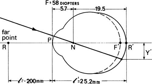 Fig. 30. Length of the reduced eye in 5 D of axial myopia is 25.2 mm. Because the power of the refracting surface is normal the position of the nodal points remains 5.7 mm; the distance from the nodal point to the retina is increased to 19.5 mm from a normal distance of 17.2 mm. |
An object at the far-point that subtends, for example, 0.1 radians at the refracting surface of the eye located 200 mm away will have a height of 20 mm because 0.1 × 200 = 20. It will subtend a smaller angle at the nodal point of the eye because the nodal point lies an additional 5.7 mm beyond the refracting surface. This angle will be 20/205.7 = 0.097 radians. The size of the retinal image of this 20-mm tall object is given by the product of the angle (0.097) times the distance of the myopic retina from the nodal point. This last distance is readily obtained when the length of the reduced eye is determined with the equation, L′ = L + F, where, L = -5 D and F = +58 D from which L′ = +53 D. Converting +53 D to the image distance ℓ′ provides the axial length of the 5-D myopic eye, viz,
We require the distance from the nodal point to the retina or 25.2 – 5.7 = 19.5 mm. The size of the retinal image is this distance multiplied by the angle subtended by the object at the nodal point, Y′ = 0.097 × 19.5 = 1.89 mm.
Image Size of Object at Far-point in Axial Hypermetropia
The small globe of the axially hyperopic eye causes the retina to intercept the convergent rays before they come to a focus as shown in Figure 31. For rays from an object to come to a focus on the retina, they must be convergent when they strike the refracting surface; that is, they must appear to originate at a virtual object located behind the retina. When the vergence of the incident light plus the power of the eye cause the image to fall on the retina, the corresponding virtual object is at the far-point of the eye, behind the retina. A 5-D hyperope has a far-point that is 200 mm to the right of the refracting surface of the reduced eye (Fig. 32). The light has a vergence L of +5 D at the eye. The image vergence is obtained as before (i.e., L′ = +5 + 58 = 63 D). The rays come to a focus at a distance
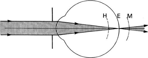 Fig. 31. The size of the retinal blur circles in hyperopia or myopia depends on the diameter of the bundle of light admitted to the eye. |
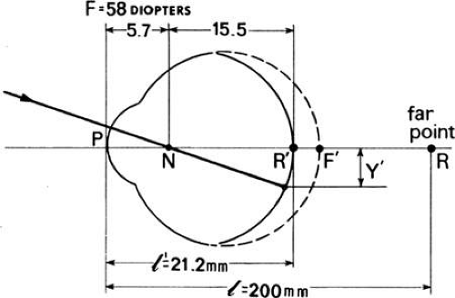 Fig. 32. The length of the reduced eye in 5 D of axial hyperopia is 21.2 mm. The position of the nodal point is 5.7 mm from the refracting surface. The distance from the nodal point to the retina is decreased to 15.5 mm from a normal distance of 17.2 mm. |
The distance from the nodal point to the retina is 21.2 – 5.7 = 15.5 mm.
Assuming once again that the virtual object is 20 mm tall, it will subtend 0.1 radians at the principal point. The nodal point is 5.7 mm closer to the virtual object, or 200 – 5.7 = 194.3 mm, therefore, the angle subtended by the object is 20/194.3 = 0.103 radians. This angle times the distance from the nodal point to the retina provides the retinal image height, Y′ = 0.103 × 15.5 = 1.60 mm. The change in image size of a far-point object in 5 D of axial ametropia compared with emmetropic image size is
Anisometropia and Prismatic Imbalance
Anisometropia is the condition in which the refractive error of one eye differs from the other. It can be characterized by unequal amounts of myopia or hyperopia, or one eye may be myopic and the other hyperopic, to which the special term antimetropia is applied. When the inequality is >2 D, the anisometropia is considered of high degree. The correction of anisometropia obviously requires lenses of unequal power. If the lines of sight of both eyes pass through the optical centers of these lenses, prismatic imbalances will not occur. Lenses cause prismatic effects; that is, displacements of the field of view, when the line of sight passes eccentrically through them. If both lenses have the same power, the prismatic effects will be identical for the two eyes, whatever the direction of gaze. When anisometropia exists and the correction lenses have unequal powers, prismatic imbalances can result that interfere with single binocular vision. This is particularly true for vertical imbalances induced when the eyes look down to read. The lines of sight will pass through points on the lens that are several millimeters below the optical centers, and the vertical displacement of the reading matter will be greater for one eye than the other.
Prismatic effect is calculated according to Prentice’s rule, which states that prismatic deviation is equal to the lens power multiplied by the distance off-center through which the line of sight passes. P = dF, where P equals deviation in prism diopters, d equals the off-center distance in centimeters, and F equals the power of the lens in diopters. A prism diopter (Δ) is a measure of ray deviation given by a linear displacement in centimeters on a screen placed 1 m from the prism (Fig. 33). A displacement Y of 1 cm at 1 m equals 1Δ.
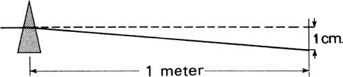 Fig. 33. One prism diopter: light is deviated through 1 cm at a distance of 1 m. |
The following prescription: OD = + 1 D; OS = + 3 D, causes an induced vertical imbalance owing to prismatic effect for a line of sight 1 cm below the optical centers as follows: Pos = 1 × 1 = 1Δ base-up and Pos = 1 × 3 = 3Δ base-up. The vertical imbalance is 3 – 1 = 2Δ base-up on left eye.
Light is deviated toward the base of a prism. In the aforementioned example, the prism is base-up because a plus lens is thickest at the optical center and the line of sight passes 1 cm below the center (Fig. 34). Myopic corrections induce base-down prismatic effects when the line of sight is depressed because minus lenses are thickest at the edge. Vertical disparities are poorly tolerated. They can cause reading problems because of difficulties in maintaining single binocular vision. Ultimately, suppression of vision in one eye may result.
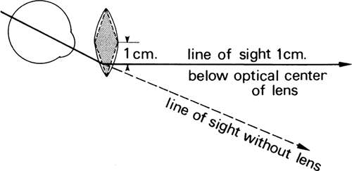 Fig. 34. Base-up prism induced when the line of sight is below the optical center of a plus lens. |
Aphakia
Inequality of images in refractive anisometropia can be reduced by fitting the lenses as close to the principal planes as possible; that is, with contact lenses. Although assessing the degree to which ametropia may be axial or refractive in origin is difficult, it is a good assumption to consider differences in the corneal powers of the two eyes as measured by an ophthalmometer as indicative of refractive ametropia. Unilateral aphakia results in refractive ametropia and the formation of unequal images.
Extraction of the crystalline lens reduces the power of the eye and changes the position of the far point. The dioptric far-point L of the aphakic eye can be found with the vergence equation L′ = L + F where F = 43 D and the image distance from the cornea to the retina, ℓ′ must be 24.4 mm. Therefore, the image vergence is L′ = 1,336/24.4 = 54.75 D. Substitution in the vergence equation will result in 54.75 = L + 43 D. Thus, L = 11.75 D. The far-point distance is ℓ = 1,000/11.75 = 85.1 mm behind the cornea.
Figure 35 compares the optical systems of the schematic and aphakic eyes. In the emmetropic schematic eye, ray 1 crosses the optical axis with a slope θ at the anterior focal point of the eye F1. After refraction, it travels parallel to the optical axis, with a height Ye. Ray 2, which has the same slope θ and is directed toward the nodal point, will be undeviated by the cornea and also will strike the retina at a height Ye. The image formed on the retina where these two rays intersect has a height Ye corresponding to a field angle θ equal to 0.1 radian or
Ye = f × θ = 17.2 (0.1) = 1.72 mm
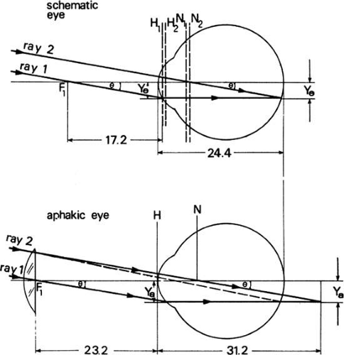 Fig. 35. Comparison of schematic and aphakic eyes. There are differences in anterior focal length, image height, and principal planes. |
In the aphakic eye, the solid lines correspond to ray paths without the correction lens. Ray 1, with slope θ, crosses the axis at the first focus of the aphakic eye, which lies 23.2 mm in front of the cornea and after refraction emerges parallel to the axis. Ray 2 is directed toward the nodal point with a slope θ and intersects ray 1 at a distance of 31.2 mm behind the eye. The retinal image is blurred. Ray 1 has a constant height at both the retina and the focal plane, which is 6.8 mm behind the retina. When the correction lens is introduced at the first focus of the eye, ray 1 is not deviated by the lens because it crosses its optical center (assuming thin lenses). Therefore, it travels to the retina along the same path as formerly. Ray 2, however, is bent (dashed lines) by the lens and intersects ray 1 at the retina at height Ya. The height of the sharp retinal image is
Ya = f × θ = 23.2 (0.1) = 2.32 mm
Thus, the size of the corrected image in aphakia compared with the size of the emmetropic image, or the relative spectacle magnification is
The aphakic image is 35% larger when the lens is at the first focal point. If the correction lens is fitted in contact with the cornea of the aphakic eye, its second focal point must coincide with the far-point 85.1 mm away; therefore, the power of the lens is
The power of the lens combined with the aphakic eye is 11.75 + 43 = 54.75 D, which corresponds to a focal length of 18.3 mm. The size of the retinal image is the product of focal length multiplied by the angle subtended by the object or 18.3′ × 0.1 = 1.83 mm. The RSM = 1.83/1.72 = 1.064 or + 6.4% when the lens is at the cornea, as is a contact lens. If the aphakia is monocular and the other eye is emmetropic, the RSM of 35% and 6.4% also will be equal to the aniseikonia induced by a spectacle and contact lens correction, respectively.
Spectacle Magnification
A spectacle lens alters the size of the retinal image of a distant object with respect to its size as formed by the eye in its uncorrected state. In this latter state, the image of an extended object is a series of blur circles, and the resultant fuzzy image appears enlarged. Constriction of the pupil of the eye reduces the size of the blur circles by reducing the size of the fuzzy image. Eliminating variation in the size of the image with pupil diameters in the uncorrected eye is necessary if this image is to be compared with the image formed in the corrected eye. Suppose, on a geometric basis, that the pupil constricts until it transmits one ray from every point on the object (this obviously is not possible because of diffraction). These rays are the chief rays. They represent the bundles of rays emitted from each point on the object. Consequently, the chief rays from opposite ends of the object properly delineate the image size on the retina of the uncorrected eye. Spectacle magnification (SM) is defined as
Spectacle magnification is concerned with the change in retinal image size induced by spectacles for a given eye rather than whether the image sizes are normal. The image size in the emmetropic schematic eye is considered normal. SM = 1/(1 – dF), where F is the thin lens power and d is the distance in meters from the lens to the eye.
Example: The spectacle magnification produced by a thin +5-D lens located 15 mm from the entrance pupil of the eye is
Relative Spectacle Magnification
The ratio of the size of the retinal image formed by a corrected eye to the size of the image formed by the emmetropic schematic eye (the normal image size) defines the relative spectacle magnification (RSM). RSM compares the sizes of sharp retinal images of distant objects formed by the corrected eye with a standard or normal size.
Because the height of the image of a distant object formed by an optical system is directly proportional to its EFL, RSM is the ratio of the EFL of the correction lens and ametropic eye (fc), to the EFL of the emmetropic schematic eye (fs).
Refracting power is the reciprocal of focal length (in meters); therefore, the RSM can be expressed as the ratio of the power of the schematic eye (FC) to the power of the lens plus the ametropic eye (FS)
The equivalent power of a combination of dioptric elements, such as the correction lens and the ametropic eye (Fc), is given by the Gullstrand equation
where: Fℓ = equivalent power of the correction lens, Fe = equivalent power of the ametropic eye, and d = distance from the lens to the first principal point of the eye. If the correction lens is placed at the first focal point of the eye, the distance d equals the first focal length of the eye, that is, d = fe or d = 1/Fe. Substituting this into the Gullstrand equation results in
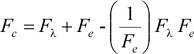
This reduces to Fc = Fℓ + Fe – Fℓ. The Fℓ terms cancel each other, leaving Fc = Fe. In other words, when a correction lens is fitted at the first focal point of the eye, the power of the combined lens–eye optical system is equal to the power of the eye alone. If Fe is substituted for Fc
in the equation for relative spectacle magnification, then RSM = Fs/Fe, which shows that RSM equals the ratio of the power of the emmetropic schematic eye to the power of the ametropic eye. If the ametropia is axial in origin, then the power of the ametropic eye equals that of the emmetropic eye and RSM equals unity (Fig. 36). This is the basis for Knapp’s Law, which states that a correction lens fitted at the first focal point in axial ametropia will produce an image of the same size as would result in the emmetropic eye. Consequently, spectacle lenses so fitted will not introduce aniseikonia in axial ametropia. Suppose two eyes have unequal amounts of axial ametropia. Their first focal points will be equal distances from the principal planes. Lenses fitted at these distances will introduce a relative spectacle magnification of unity, which means that the images of the two eyes will be equal to that of the standard eye and, therefore, equal each other. If the ametropia is refractive in origin and of unequal amounts for the two eyes, however, the first focal points will be at unequal distances from the principal points. Correction lenses in a spectacle frame could not both lie in the respective focal planes of the eyes unless the frame was skewed. Therefore, at least one lens would introduce an RSM of value other than unity, and the images would be unequal.
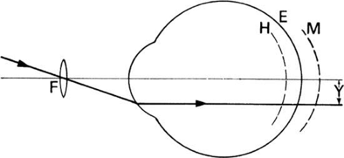 Fig. 36. Path of the chief ray through a correction lens at the anterior focus of axial ametropic eyes. |
Retinal Image Size after Spectacle Correction of Axial Myopia
The sole condition to be satisfied by the correction lens is that its second focal point coincides with the far-point of the eye. Theoretically, the lens can be placed anywhere between the cornea and the far-point provided that the aforementioned condition is satisfied. The closer the lens is to the far-point, however, the shorter its focal length must be, and the smaller the image of a distant object will be in the focal plane. It is this image that the eye views. Obviously, as the image at the far-point becomes smaller, it will subtend a smaller angle at the nodal point of the eye and the retinal image will shrink correspondingly. In Figure 37a, the negative correction lens is a short distance from the eye. It forms a virtual image of the collimated off-axis rays, whose height at the second focal plane (also far-point plane) is Y1′. In Figure 37b, the eye views this virtual image point at the second focal plane (also par-point plane). It subtends in angle θ at the eye’s nodal point and forms a retinal image of corresponding subtense.
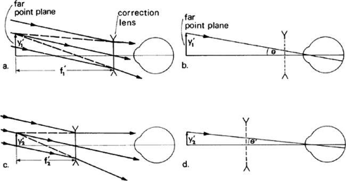 Fig. 37. Minification by spectacle lens in myopia. a. The lens is close to the eye and forms an image of height Y1′, which subtends an angle θ at the eye, as shown in b. c. When the lens is fitted farther fro the eye, it forms an image of height Y2′, which subtends a smaller angle θ’ at the eye, as shown in d. The farther from the eye that the correction lens is fitted, the greater is the minification. |
Figure 37c illustrates the geometry that results when a negative correction lens of shorter focal length is placed farther from the eye to cause the focal point to coincide with the far-point. The collimated rays from the object approach this lens with the same slope as before, and after refraction, they virtually are focused at the far-point plane. The height Y2′ in this plane is reduced from that of the previous correction, however, and this image subtends a smaller angle θ′at the nodal point of the eye. Consequently, the retinal image is reduced in size (Fig. 37d). Usually, the farther a negative correction lens is fitted from a myopic eye, the smaller the retinal image will be. This reduction in image size, as the distance between lens and reduced eye is increased, is shown in Figure 38 and Table 3 for a 5-D axial myope and a distant object that subtends 0.1 radians. The table shows how the negative power of the lens must be increased as the lens is fitted farther from the eye and closer to the far-point. The third column shows the equivalent power of the lens and eye calculated with the equation
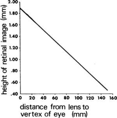 Fig. 38. Size of the retinal image as a function of lens-to-eye distance for a distant object that subtends 0.1 radians and an axial myopia of 5 D. The far point is 200 mm away. |
TABLE 3. Retinal Image Size and Spectacle Magnification in 5-D Axial Myopia | ||||||||||||||||||||||||||||||||||||||||||||||||||||||||
|---|---|---|---|---|---|---|---|---|---|---|---|---|---|---|---|---|---|---|---|---|---|---|---|---|---|---|---|---|---|---|---|---|---|---|---|---|---|---|---|---|---|---|---|---|---|---|---|---|---|---|---|---|---|---|---|---|
| ||||||||||||||||||||||||||||||||||||||||||||||||||||||||
The reciprocal of F is the equivalent focal length and is tabulated in the fourth column. Because the image size is proportional to focal length, the reduction in image size that clearly occurs, as the correction lens is fitted farther from the eye, is the result of this reduction in equivalent focal length. Tabulated in the fifth column is the actual image size. It is the product of the equivalent focal length and the angle subtended by the object that is, in this case, 0.1 radians multiplied by EFL.
Retinal Image Size after Spectacle Correction of Axial Hyperopia
As expected, plus lenses will produce image size effects opposite that of negative lenses. The plus lens correction also must fulfill the condition of superimposing its second focal point on the far-point of the eye. For the hyperope, however, the far-point is behind the eye. The plus correction lens can be fitted no closer to the far-point than the vertex of the eye. Theoretically, of course, the lens can be fitted any distance in front of the eye. The closer to the eye the lens is fitted, however, the shorter its second focal length must be to maintain coincidence with the far-point. Concomitantly, the image formed by the lens at the far-point plane will be smaller. The eye, in effect, views this image, which will subtend correspondingly smaller angles at the nodal point.
Retinal Image in Refractive Ametropia
A 5-D refractive myope can be illustrated by a reduced eye with a length of 22.9 mm, but with a refractive power of 63 D. The first focal length of the eye = f1 = 1,000/63 = 15.9 mm. The second focal length = f2 = 1,336/63 = 21.2 mm or 1.7 mm in front of the retina. The chief ray from a distant object that subtends 0.1 radians will have an uncorrected image height at the retina of 0.1 × 22.9/1.336 = 1.72 mm.
The uncorrected image size in refractive ametropia is equal to the standard image size. This means that spectacle and relative spectacle magnification will be identical because spectacle magnification is referred to as the uncorrected image size and RSM is referred to as the standard image size. A correction lens placed at the first focal point of this eye results in an equivalent power for the lens and eye combination that is equal to the power of the eye alone, that is, 63 D. The second principal plane of the combination is at the cornea, that is, 21.2 mm from the retina. A sharp image is formed on the retina. Because the first focal length is 15.9 mm, the size of the sharp retinal image is (15.9) (0.1) = 1.59 mm. The magnifications are
If the lens is placed in contact with the refracting surface, the net power is -5 + 63 = 58 D. The power, focal length, and axial length of the corrected refractively myopic eye are the same as the standard eye. The image will be 1.72 mm long, and the magnifications are
Usually, the closer a lens is fitted to the refractive ametrope, the less magnification there will be. The magnification effects for a correction lens at the first focal point of the eye compared with a contact lens in axial and refractive myopia are summarized in Table 4.
TABLE 4. Comparison of Magnification Effects and Retinal Image Sizes in Corrected 5.0 D Axial and Refractive Myopia | ||||||||||||||||||||||||||||
|---|---|---|---|---|---|---|---|---|---|---|---|---|---|---|---|---|---|---|---|---|---|---|---|---|---|---|---|---|
| ||||||||||||||||||||||||||||
Aniseikonia and Relative Spectacle Magnification
Aniseikonia is a condition where a relative difference exists in the size, shape, or both of the ocular images of the two eyes. This inequality may be owing to unequal retinal image differences and cortical image differences. The latter is caused by the distribution of the retinal receptive elements and the physiologic and cortical processes involved in vision.
Aniseikonia is produced by RSM in anisometropia. For example, apply the myopic conditions of Table 4 to the right eye and have the left eye be emmetropic. The left eye retinal image size of a 0.1-radian target will be 1.72 mm. Axial myopia corrected at the first focal point results in a 1.72-mm image. Refractive myopia that is corrected with a lens in contact with the reduced eye also results in a 1.72-mm image. These right eye corrections produce no aniseikonia or RSM; however, the axial myopia correction at the eye produces a 1.89-mm image. This results in +9.9% aniseikonia and RSM. Similarly, the refractive myopia correction at the first focal plane produces a 1.59-mm image or -7.6% aniseikonia and RSM.
Image Quality
Limits on Image Quality
Paraxial optical calculations provide point images of point objects. Real rays do not come to a point focus because of aberrations and diffraction. Although aberrations can be reduced to zero; for example, a paraboloidal telescope mirror will have zero spherical aberration; the image of a star will be affected by diffraction or the bending of rays as they are reflected by the edge of the mirror. Diffraction limits the quality of an image.
Pupillary Aperture, Diffraction, and Resolving Power
That light consists of rays traveling in straight lines, works well for finding object and image positions and sizes; however, are there rays of light? A direct experiment to elucidate this might be to allow a bundle of rays from a point source, such as a star, to pass through a circular aperture. As the aperture is made smaller, fewer rays should be transmitted. If these rays are observed on a screen, the spot diameter also should become smaller. What happens, however, is that at first the spot on the screen does constrict. At a certain aperture diameter setting, as the aperture continues to shrink, the spot on the screen begins to enlarge (Fig. 39). This phenomenon, known as diffraction, sets a limit to the minimum size of the image. Diffraction is a bending of light caused by the edge of an aperture or the rim of a lens. Even a perfect lens, free from aberrations, will not focus light to a point, owing to diffraction. Instead of a point image, a lens with a circular aperture or pupil produces a blur consisting of a series of concentric bright and dark rings (Figs. 40 and 41). At the center of this diffraction pattern is a bright spot known as the Airy disc, so called, because Sir George Airy, (1801–1892) Astronomer Royal, was the first to calculate the energy distributions in the pattern. Approximately 84% of the total energy of the diffraction pattern is in the Airy disc. The remaining energy is distributed in the surrounding rings that become progressively fainter, as shown in Table 5.
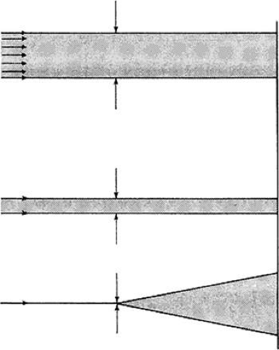 Fig. 39. Diffraction due to reducing the size of the aperture. |
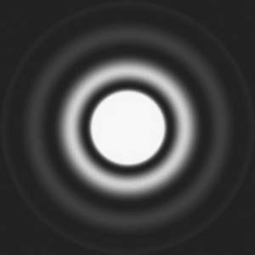 Figure 40. Airy disk and surrounding rings produced by a circular aperture. |
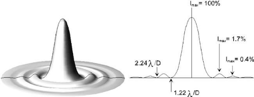 Figure 41. Fraunhofer diffraction by a circular aperture. The intensity distribution is shown at right. |
Table 5. Energy Distribution by a Circular Aperture in the Diffraction Image | |||||||||||||||
|---|---|---|---|---|---|---|---|---|---|---|---|---|---|---|---|
|
Regardless of how well a telescope, for example, may be corrected, this will be the image pattern for a star. The angular subtense of this pattern depends only on the wavelength of light and the diameter of the aperture of the telescope or other optical device. In particular, the radius of the Airy disc subtends an angle with respect to the lens of
Where λ equals the wavelength of light and d is the diameter of the lens aperture in the same units as wavelength. This equation shows that the diffraction blur increases directly with the wavelength and inversely with the aperture diameter. A red light source will be imaged with nearly twice the diameter of a blue light source. Doubling the aperture diameter will halve the diffraction blur.
Figure 42 illustrates the intensity distribution of the diffracted images of two stars in the focal plane of a telescope or any well-corrected optical system. Diffraction limits the resolution of optical systems ranging from the eye to the telescope at Mt. Palomar. Two large diffraction images will run together and appear single at larger angular separations than two fine diffraction patterns. Therefore, the smaller the aperture, the coarser is the resolution because of diffraction. For example, if a telescope is pointed at two equally bright stars, two diffraction patterns will be produced. The smaller the angle between the stars, the closer the patterns will be imaged. As shown in Figure 42a, the two star images are not resolved, when the peaks of their patterns are separated by an angle less than the angle of the radius of the Airy disc. The intensities of the overlapping discs add to form a single peak (the dotted line). Rayleigh showed that stars are resolvable when the two stars were separated by an angle equal to the radius of the Airy disc (i.e., the peak θ1, of pattern 1 falls on the first dark ring of pattern 2, and the peak θ2 of pattern 2 falls on the first dark ring of pattern 1. As illustrated in Figure 42b, the addition of the intensities of the two overlapping patterns results in a dip in the combined patterns (dotted line), which is a sufficient drop in brightness to be perceived and make the patterns resolvable. Other investigators have shown that an even smaller dip is sufficient for resolution and so frequently an angular separation of θ = 1.0λ/d is used instead of θ 1.22/ λ d. The wavelength is specified in nanometers (nm), which is equal to millimicrons, a now obsolete unit. Further separation makes them easily resolvable.
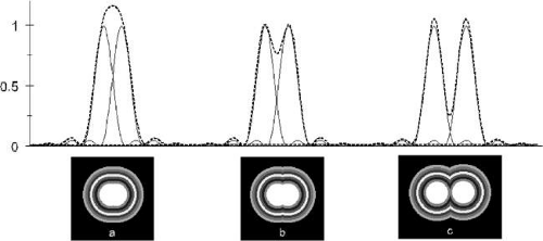 Figure 42. a) Intensity distributions for two unresolvable points separated by an angle less than 1.22λ/D; i.e., less than the radius of the airy disc. The dashed line represents the combined intensity of the two patterns. b) Intensity distributions for two just resolvable points separated by an angle of 1.22λ/D (Rayleigh criterion). This Separation equals one disc radius; the peak of one pattern falls on the first minimum of the other. The dip in the combined intensity curve is sufficient to resolve the patterns. c) Further separation between the points makes them easily resolvable. |
For example, the angular resolving power (RP) of the eye, given an eye pupil diameter of d = 2 mm and λ = 555 nm = 0.000555 mm, is
Because 1 minute of arc equals 0.00029 radians, RP = 0.00034/0.00029 = 1.17 minutes of arc. If 1.0 λ/d, is used, RP = 0.000278 radians and the resolution becomes 0.96 minutes of arc.
A 20/10 Snellen E has a resolution angle of 1 minute. This shows how remarkably close the resolving power of the eye in white light is to the theoretic limit. The equation shows that the resolving power is inversely related to pupil diameters. In other words, because d is in the denominator, if d becomes smaller as the pupil constricts, then the resolvable angle gets larger or visual acuity becomes poorer. If the resolving power of the eye was solely dependent on diffraction effects, then a large pupil would improve acuity proportionately. A 6-mm pupil should result in a resolving power of 0.782 = 0.39 minutes or 24 seconds. This does not happen because the eye is not a perfect optical instrument. Its aberrations become more pronounced as the pupil dilates. Further complicating the situation, is the effect of illumination level on acuity and the directional sensitivity of the retinal elements or Stiles-Crawford effect. As a practical result of the interaction of diffraction, aberrations and retinal illumination optimal acuity occurs over an intermediate range of pupil diameters, viz, 2 to 3 mm.
A person with uncorrected myopia will obtain improved acuity with an artificial pupil as its diameter is reduced. This is because the blur spot on the retina shrinks as the pupil constricts and, in effect, this person’s depth of focus increases. A reduction in pupil size is reached, however, such that the blur owing to diffraction begins to exceed the geometric blur caused by the pinhole pupil. Further reduction of the pupil increases the angular subtense of the Airy disc in accordance with θ = 1.22λ/d, and the resolving power of the eye will decrease.
Modulation Transfer Function-diffraction Limited
Resolution, classically, has been measured with high contrast (black and white) targets. At the limit of resolution, the contrast in the image, between what should be black and white lines, is reduced to a barely discriminable level. Resolving power provides no information about the contrast in the images of coarser patterns that are resolvable. Photographs generally contain a wide range of detail or spatial frequencies. The trunks of trees in the woods are coarse or low spatial frequency targets that are easily resolvable, but the leaves on the trees or the bark on the trunks are higher spatial frequency targets. The quality of their photographic images depends on how much contrast they contain. It is not solely dependent on the highest spatial frequency that is just resolvable by the lens. Generally, the contrast in the image should be as high as possible at all spatial frequencies.
The modulation transfer function (MTF) describes the contrast of all spatial frequencies in the image. Ideally, the light distributions across the images of a series of bar targets should be square waves (i.e., have sharp edges, and flat peaks and valleys), despite spatial frequency. At best, the image of a point is a diffraction pattern. Lens aberrations will smear the image even more. The light distribution in the image is called a point spread function. If the object is a line (i.e., an infinite number of points), the image is a line spread function. Figure 43. Modulation describes the distribution of light across a series of parallel sinusoidal line spread functions as shown in Figure 44. The peak and valley intensities are labeled Imax and Imin.
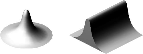 Figure 43. Point and line spread functions. |
 Figure 44. Modulation of a sine wave. |
The spread function causes the sharp edge of an object to have a rounded image luminance profile. This rounded luminance profile on both sides of a coarse square wave or bar target will be a blurred region between a flat maximum (L = 1) and minimum (L = 0) luminance distribution. As progressively finer bar targets are imaged by the optical system, their luminance profiles are progressively imaged closer together and run into each other. In other words, increasingly more light invades what should be the dark areas (Fig. 45). As a result, the dark areas gain illumination and the light areas lose illumination. The ideal square wave luminance distribution of the image becomes degraded into a sinusoidal distribution (Fig. 46). As the bar targets become more closely spaced (higher spatial frequency), the difference between the maximal and minimal luminance lessens or the contrast, expressed as a modulation, is reduced. The ideal MTF targets are not bars with square wave luminance distributions but gratings that vary sinusoidally in luminance. Because the luminance distributions in their images are always sinusoidal, their mathematical treatment is facilitated.
 Figure 45. a) A two-cycle coarse square-wave object. b) luminance distribution in the object. c) overlapping line spread image functions. d) resultant image edge function. e) blurred edges of the image. |
 Figure 46. a, b, c) Square wave objects of high spatial frequencies have images with sinusoidal light distributions. d, e, f) still higher spatial distributions results in deceased modulation. (After Modern Optical Engineering by W. J. Smith) |
About two cycles of an object pattern of black and white bars is shown in Figure 45a. The square wave brightness of the object is shown in Figure 45b. The bright bars consist of an infinite number of bright lines. Each bright line is imaged as a line spread function. Overlapping line spread functions, as shown in Figure 45c, cause the sharp edge of the bright bars to be imaged with a rounded intensity profile, thus forming the edge function in Figure 45d. In effect, some light spills into the adjacent dark area, and the edges of the bars are blurred as indicated by Figure 45e.
As the spatial frequency increases (i.e., as the bright and dark stripes become narrower), the edge functions overlap. The peak intensity in the bright stripes begins to diminish and the dark stripes begin to brighten. The square wave target is imaged with a sinusoidal illumination distribution. Its amplitude, which is a measure of the contrast, decreases as spatial frequency increases until the contrast is so small that the illumination in the image looks uniform and no pattern is discernable (Fig. 46).
Stay updated, free articles. Join our Telegram channel

Full access? Get Clinical Tree


