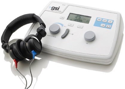
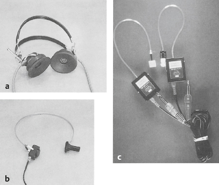
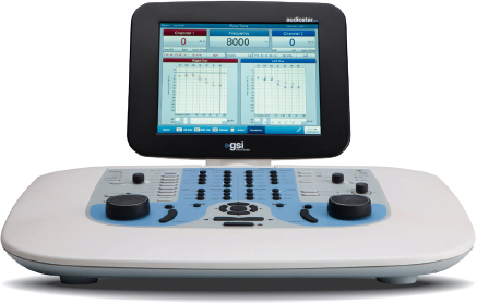
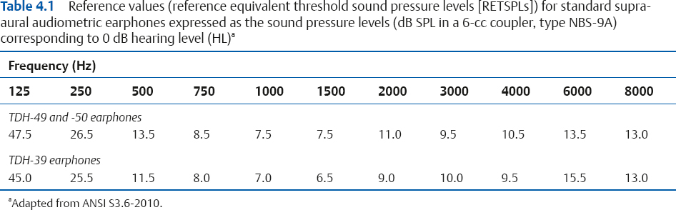
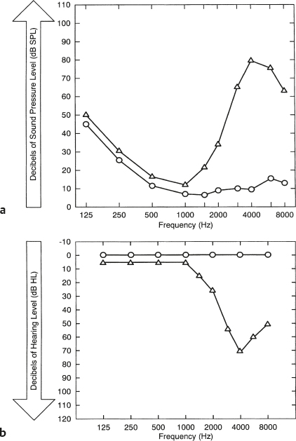
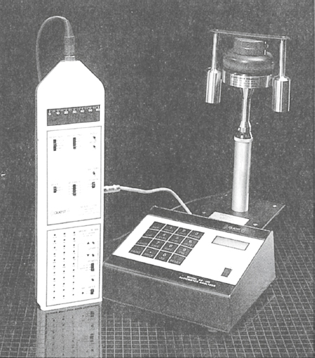
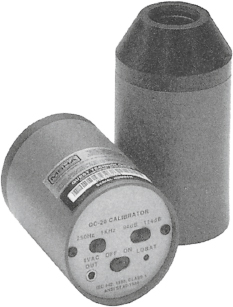
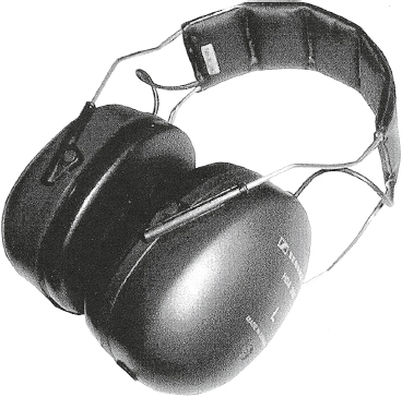
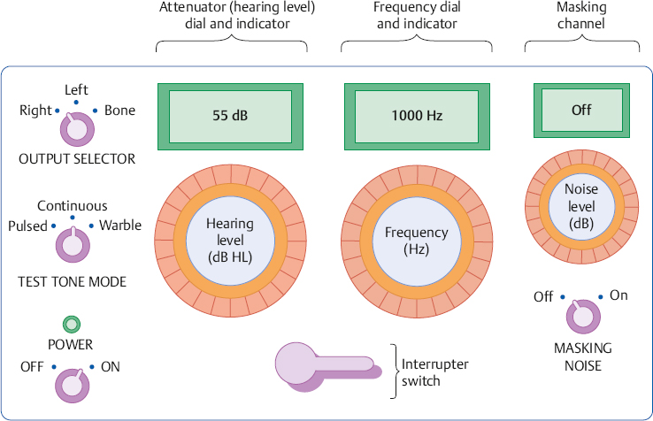
4 The Audiometer and Test Environment The principal tool used in the process of evaluating a patient’s auditory functioning is the audiometer. Fundamentally, the audiometer is nothing more than an electronic device that produces and delivers sounds to the patient. What makes the audiometer unique is that these sounds are very specific: we know precisely what is being presented to the patient, and we can be confident that these sounds will be consistent from audiometer to audiometer. A basic audiometer should make it possible to perform the most fundamental audiological tests, which involve determining how much intensity is needed for a patient to hear pure tones at different frequencies. The pure tone audiometer must be able to produce pure tones at certain frequencies, precisely control the levels of these tones, and deliver them to the patient in the manner intended by the audiologist. A typical pure tone audiometer is shown in Fig. 4.1. The components of an audiometer are shown in Fig. 4.2. The power switch controls the electrical supply to the instrument, and there is often a power indicator lamp to show whether it is on or off. Test tones are presented to the patient by turning them on and off with a button called the interrupter. The frequency control is used to select among the various test frequencies. Most audiometers include the frequencies 125, 250, 500, 750, 1000, 1500, 2000, 3000, 4000, 6000, and 8000 Hz. The pure tones themselves are produced by a circuit within the audiometer called a pure tone oscillator. There is a stimulus or tone mode switch that allows the test tone to be presented either continuously on or pulsed on and off at a regular rate. Another mode produces a warble tone, which means that the frequency varies periodically (e.g., 1000 Hz ± 5%) rather than staying steady over time. This feature is not commonly found in basic audiometers. The intensity of the test signal is controlled by the attenuator or Hearing Level control. (Frequency dial, attenuator or HL dial, and dial readings are convenient terms that continue to be used even though many digital instruments have replaced dials with other kinds of controls.) Unlike common volume controls, attenuators are calibrated, which means that the markings on the attenuator refer to specific physical values and increments. Setting the attenuator to “45 dB HL” will cause the sound coming out of the earphone to have a sound pressure level (SPL) that actually corresponds to 45 dB HL; and changing the attenuator setting by 5 dB means the sound pressure level will really change by 5 dB. Most audiometers have attenuators that are calibrated in 5 dB steps, and more sophisticated models also provide for testing in 1 dB, 2 dB, or some other step size. The range of intensities that can be tested usually goes from as low as –10 dB HL up to 115 dB HL for air-conduction and ~ 70 dB for bone-conduction. The testable range varies for each type of signal and is indicated on the audiometer. Fig. 4.1 An example of a basic pure tone audiometer. (Courtesy of Grason-Stadler, Inc.) Finally, an output selector is used to direct the signal to the right or left earphone, or to the bone-conduction vibrator. Fig. 4.3 shows examples of typical audiometric earphones and a bone-conduction vibrator. The standard audiometric headset includes a headband that holds two earphones, each of which is surrounded by a rubber cushion. They are often called supra-aural earphones because the earphone/cushion combination is worn over the ear. This is in contrast to the less frequently used circumaural earphones, which have cushions that fit around the ears. Insert earphones have a pliable earpiece that is inserted into the external auditory canal, and are also used for various clinical purposes, as discussed in Chapters 5 and 9. A bone-conduction vibrator is usually held against the mastoid by a spring-like headband. The audiometer described so far would be considered a single-channel instrument because it can produce only one signal. However, many pure tone audiometers have a second channel that can produce a masking noise. The second channel has its own interrupter switch and attenuator. The noise signal is produced by a circuit inside the audiometer called a noise generator. It is premature to discuss masking at this point, except to say that we might need to put a masking noise into the left ear to prevent it from hearing the test tones that are being presented to the right ear. Fig. 4.3 Examples of (a) standard supra-aural audiometric earphones, (b) a bone-conduction vibrator, and (c) insert receivers. Clinical audiometers such as the one depicted in Fig. 4.4 include all of the features of pure tone audiometers, plus a wide array of features that enable them to perform sophisticated tests with tones and many other kinds of signals. These instruments also include microphones; inputs for tape and CD players that are used to present recorded tests; patient response microphones; an intercom system; a patient response signal; computer interface; etc. Some instruments provide for testing in the 8000 to 16,000 Hz range, and are identified as extended high-frequency audiometers. In addition, the output selector of a clinical audiometer provides a wide choice of output transducers, such as (1) the right or left earphone, (2) the right or left insert receiver, (3) the bone-conduction vibrator, (4) loudspeakers, and (5) any combination of these. How many and which ones of these and other functions are provided varies by manufacturer and model. In fact, the term clinical audiometer is really professional jargon for an instrument that is sufficiently versatile and accurate to meet the extensive clinical needs of an audiologist. Technically, audiometers are actually specified in terms of type based on standards for the functions they provide and the accuracy of these capabilities (ANSI S3.6-2010). Fig. 4.4 Example of a state-of-the-art clinical audiometer that is able to perform a wide variety of clinical tests. (Courtesy of Grason-Stadler, Inc.) Recall from Chapter 3 that our actual hearing sensitivity in decibels of sound pressure level (dB SPL re: 2 × 10⁻⁵ N/m2 or 20 μPa) is not the same at every frequency. For example, the average normal person needs 26.5 dB SPL just to barely hear a 250 Hz tone, but only 7.5 dB SPL to just hear a 1000 Hz tone. Table 4.1 shows what the normal threshold SPLs are when using typical audiometric earphones. We consider these values to be normal reference values—more technically, reference equivalent threshold sound pressure levels (RETSPLs)—because they are the physical intensities needed by normal people to reach the threshold of hearing. In fact, when we say a person has a “hearing loss,” we really mean that she requires higher SPLs than these values to just hear a sound; the more her thresholds deviate from these reference values, the worse is her hearing loss. It is inconvenient to have different reference values at every frequency, particularly when they are “odd” numbers like 47.5, 13.5, 7.5, and 11. Life would be more pleasant if we could use the same number to represent the normal value at every frequency, especially if that reference could have a convenient value like zero. How can we make that happen? Even though the reference values in Table 4.1 have different sound pressure levels, they are all just barely audible—and therefore equally audible. In other words, these different physical intensities are the same with respect to hearing. Hence, we can say that each of these different sound pressure levels has the same hearing level. What is the hearing level of each of these threshold sounds? Because each of the SPLs in Table 4.1 is the softest sound that can be heard, it makes sense to say that they constitute the reference values for hearing. We already know that a reference has a decibel value of zero. In other words, each of these threshold SPL values corresponds to a hearing level (HL) of 0 dB, or simply 0 dB HL. Now we can say it takes 26.5 dB SPL to reach 0 dB HL at 250 Hz, 7.5 dB SPL to reach 0 dB HL at 1000 Hz, and 10.5 dB SPL to reach 0 dB HL at 4000 Hz. The circles in Fig. 4.5 show these normal threshold reference values as a function of frequency in terms of both SPL (Fig. 4.5a) and hearing level (Fig. 4.5b). Notice that the SPL graph is read upward whereas the HL graph is read downward. The curved line in Fig. 4.5a demonstrates that these thresholds have different physical values in dB SPL, but they fall along a straight line at 0 dB HL in Fig. 4.5b because they have the same hearing levels. We might say that hearing level considers each reference SPL value to be 0 dB HL. For illustrative purposes, the threshold curve of a person with a hearing loss at high frequencies is shown by the triangles in the figure. The hearing loss (triangles) is seen as a deviation from the normal values (the circles). Notice how much easier it is to think of “normal” as a straight line. Fig. 4.5 Normal hearing thresholds (circles) as a function of frequency appear (a) as a curved line representing different physical values in dB SPL and (b) as a straight line representing the same hearing values in dB HL. The triangles show the thresholds of a person who has a hearing loss in the higher frequencies in (a) dB SPL and (b) dB HL. Notice how intensity increases upward in frame (a) and downward in frame (b). (Adapted from Gelfand [1981], with permission.) Let us now put the idea of hearing level together with the audiometer. The attenuator dial on the audiometer reads in decibels of hearing level (dB HL), and all of the reference values shown in Table 4.1 are built into the audiometer’s circuitry. When the tester sets the attenuator dial to any value in dB HL, the audiometer automatically adds the reference value needed to produce the corresponding physical intensity. For example, when the frequency is set to 1000 Hz (where the reference value is 7.5 dB SPL), an attenuator setting of 0 dB HL causes the audiometer to produce a tone of 0 + 7.5 = 7.5 dB SPL and an attenuator setting of 55 dB HL results in 55 + 7.5 + 62.5 dB SPL If the frequency is set to 500 Hz (where the reference value is 13.5 dB SPL), then 0 dB HL yields 0 + 13.5 = 13.5 dB SPL and 65 dB HL would result in a tone of 65 + 13.5 = 78.5 dB SPL For most purposes, the SPLs are transparent to us and we deal only in terms of the hearing level values in dB HL. We need to know what sound is actually being presented to the patient. For example, when the frequency dial says “1000 Hz” and the attenuator says “40 dB HL,” the audiometer should actually be producing a 1000 Hz tone at 40 dB HL. For this reason, there are national and international standards that specify the physical characteristics of the sounds that are produced by an audiometer. These standards also specify the tolerances for these characteristics, which means how far the actual sounds are allowed to deviate from the standard values. Most of these requirements are contained in the American National Standard Specifications for Audiometers (ANSI S3.6 2010). Calibration is the process of making sure that an instrument is really doing what it is supposed to be doing. In this case, it is the process of making sure the audiometer is in compliance with the applicable standards. When an audiometer is calibrated to the ANSI S3.6-2010 standard, it is said to be calibrated to ANSI/ISO Hearing Level, and we say that the values are expressed in decibels of ANSI/ISO Hearing Level, or dB re: ANSI-2010 (or similar terminology). The term ANSI/ISO reflects the corresponding international standards, ISO 389-1–5,7 (1994a–c, 1998, 2005, 2006), as well as the ANSI standard. An audiometer is calibrated with a sound level meter to ensure that the correct SPLs are being presented to the patient. More sophisticated calibration measurements employ other instruments as well. For example, a frequency counter is used to determine whether the test frequencies are within acceptable limits. Other instruments such as oscilloscopes and distortion analyzers are used to determine the timing characteristics of the test signal and the types and amounts of distortions that might be present. An audiometer calibration system incorporating many of these components is illustrated in Fig. 4.6. Air-conduction calibration involves measuring the sounds produced by the earphones, and is done separately for each earphone. As shown in Fig. 4.6, the earphone is placed on an NBS-9A coupler, which is a metal cavity having a volume of 6 cc. This coupler is used because it roughly approximates the acoustical characteristics of the ear, and is often called a 6-cc coupler or an artificial ear. A high-quality microphone is located at the bottom of the coupler. The microphone is connected to the audiometer calibrator or sound level meter, which measures the actual sound pressure level being produced by the earphone. Notice that the microphone measures the sound coming from the audiometer earphone is a very specific way, as it exists within the 6-cc coupler. The accuracy of the sound level meter itself is often confirmed using a sound level calibrator, which is a device that produces a precisely controlled signal (Fig. 4.7). Fig. 4.6 Air-conduction calibration using an audiometer calibration system. Notice that the audiometer’s earphone is mounted on an artificial ear (6-cc coupler). (Courtesy of Quest Technologies, Inc.) Fig. 4.7 Example of a sound level calibrator used to confirm the accuracy of the sound level meter. The sound level meter’s microphone is inserted into the depression at the end of the calibrator, which is then set to produce one or more precisely known test signals. (Courtesy of Quest Technologies, Inc.) Table 4.1 shows the reference values specified by the ANSI S3.6-2010 standard for TDH-39, TDH-49, and TDH-50 supra-aural earphones (Telephonics). We will use the values for TDH-49 and TDH-50 earphones for the purpose of illustration because these are the values most commonly used. However, reference values will be provided for other types of receivers as well. The reference values for Etymotic ER-3A and Aero EARtone 3A insert receivers are shown in Table 4.2. The reference values for insert earphones are obtained using special types of 2-cc couplers or occluded ear simulators instead of the 6-cc NBS-9A coupler described for use with standard audiometric earphones. Special measurement couplers are used because insert receivers are placed into the ear canal instead of being worn over the ear, and are used for many hearing aid measurements. Extended high-frequency audiometry involves testing patients in the frequency range from 8000 through 16,000 Hz, and requires the use of special insert receivers or circumaural earphones. The insert receivers look like the ones we saw in Fig. 4.3, and an example of circumaural earphones is shown in Fig. 4.8. Normal reference values (RETSPL) for extended high-frequency audiometry are provided for Etymotic ER-2 insert receivers and Sennheiser HDA200 circumaural earphones in Table 4.3. The outputs of the insert receivers are tested with an occluded ear simulator. Because of their shape, a flat plate adapter is used to couple circumaural earphones to the artificial ear. It is very simple to perform a sound level calibration check once we know the reference SPLs and the equipment has been set up as shown in Fig. 4.6. The following procedure is used at each test frequency and for both earphones: 1. Select the frequency. 2. Set the attenuator to a convenient level, such as 70 dB HL. (We use a high level so that the intensity of the tone will be well above any noise levels in the room.) 3. Turn on the tone. 4. Read the meter on the audiometer calibrator (or sound level meter) to measure the actual sound pressure level that is produced by the earphone. Fig. 4.8 Circumaural earphones used for extended high-frequency audiometry. (Photography courtesy of Sennheiser electronic GmbH & Co. KG.)
 The Audiometer
 Hearing Level
 Audiometer Calibration
Air-Conduction Calibration
Stay updated, free articles. Join our Telegram channel

Full access? Get Clinical Tree


