The resultant “CELLplant” device (Fig. 22.2) was a filtering implant of similar shape to the first model shown on the left in Fig. 22.1 and made from the cellulosic membrane material widely used for hemodialysis filtering [10, 11]. This material exhibited many of the needed characteristics.
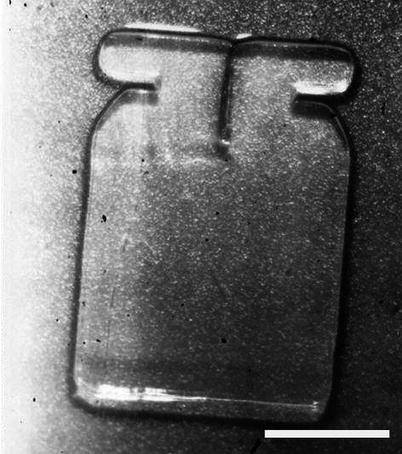
Fig. 22.2
Image of a hydrated CELLplant device. Once hydrated, CELLplant thickness was about 75 μm. White scale bar represents 3 mm (Used with permission of Dr. Robert Nordquist)
Toxicity, safety, and efficacy of the CELLplant device were successfully demonstrated in rabbits [10, 11]. In a first short study, the average IOP dropped from 22.0 to 14.3 mmHg in the eyes treated with the CELLplant device, whereas the control eyes treated with a normal filtering surgery had an average IOP of 20.2 mmHg after 70 days (p-value of 0.001). A 1-year study showed similar results with an average IOP reduction more than 30 % at the end of the experiment (Fig. 22.3). None of the rabbits developed corneal decompensation, conjunctival erosion, or uveitis as a result of the implants. Scanning electron microscopy of the angle structures showed no evidence of corneal endothelial damage, iris atrophy, necrosis, or hypertrophy although there was iris touch. In all experimental eyes, except for one due to malposition of the implant, a functional filtering bleb was maintained, and the fistulas remained well open. Similar IOP results were also obtained in a cat with glaucomatous eyes.
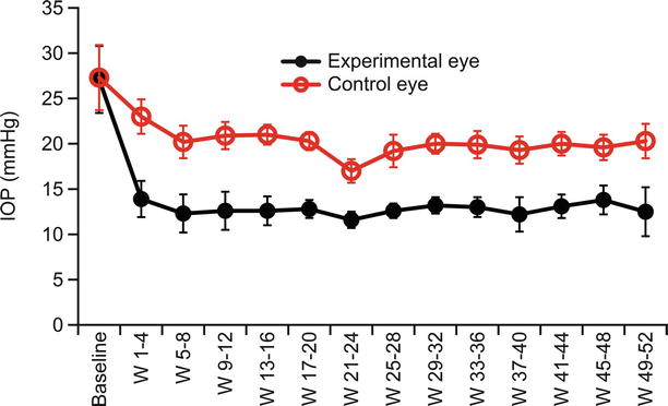
Fig. 22.3
One-year IOP follow-up in rabbits. For each animal (12 rabbits in total), one eye was implanted with CELLplant (experimental eye – black line) and the contralateral eye was used as control (open markers, red line)
Based on the promising preliminary animal studies devoid of complications, a human clinical trial was conducted in the Republic of China in 1994–1995 by Dr. Li [10, 11, 17]. Twenty-three patients, exhibiting uncontrolled glaucoma of various type (neovascular, open angle, closed angle, traumatic) averaging over 60 mmHg of IOP and with previous failure to respond to conventional medical treatment, underwent filtration surgery with the CELLplant seton. The average IOP was 12 mmHg by the third-day postoperative, and all remained below 18 mmHg through 180 days. During the 24-month follow-up of the study (13 cases), no postoperative hypotony; complications including hyphema, uveitis, or infection; or flat chambers were observed, and the devices still functioned at the end of the study.
The feasibility of the surgical procedure and the promising results of the CELLplant device in significantly and sustainably dropping the IOP have been reported in both animal and human trials; further bench testing and an animal study on rabbits were conducted in response to the then newly issued (1998) US FDA Guidelines for Aqueous Shunts 510(k) (later issued as ANSI Z80.27-2001 Aqueous Shunts for Glaucoma Application) with the aim of commercializing the CELLplant device. Although IOP results correlated with those earlier observed (see Fig. 22.3), this animal study revealed certain issues of long-term fibrosis and mechanical fragmenting of the cellulosic material [18, 19]. The use of a more robust, long-term stable material was therefore required to overcome the drawbacks of the cellulose and to provide a future for Norquist’s design. This material was found in the STAR® Biomaterial, invented at the University of Washington in 2003.
STAR Material
Healionics’ proprietary STAR® Biomaterial is a porous tissue engineering scaffold designed to promote healing of tissue around implanted medical devices with less scarring, improved vascularity, and a more stable long-term tissue-biomaterial interface.
A Precision-Pore Structure
STAR® Biomaterial contains a precisely controlled pore geometry made with a sphere-templating process developed at the University of Washington by Andrew Marshall and Buddy Ratner. Healionics has exclusively licensed patents from the University of Washington covering porous biomaterials with the optimized pore size for promoting vascular ingrowth and the sphere-templating methods for making them [7–9].
The sphere-templating process yields a pore structure with interconnected uniformly sized spherical pores. Since the size of the necks formed during the sintering step is carefully controlled, the size of the interconnections, or “throats,” between the pores of the templated biomaterial is also precisely controlled. Figure 22.4 shows a scanning electron microscopy (SEM) image of the sphere-templated STAR® pore structure, with uniform dimensions of the pores and pore throats indicated. The ordered arrangement of the pores is an outcome of the fabrication method but is not believed essential to biological function so long as overall porosity and interconnection is maintained.
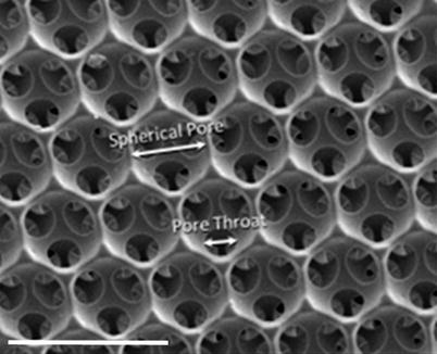
Fig. 22.4
SEM image of STAR® Biomaterial surface showing uniform dimensions of the pores and pore throats. White scale bar represents 50 μm
The pore size and structure of the STAR® Biomaterial are optimized for several biological effects that contribute the functionality of the STARfloTM Glaucoma Implant. These effects include maximized recruitment of macrophage cells into the pores, the subsequent vascularization of the implant with high capillary density, and the minimization of fibrotic scarring in the peri-implant tissues.
Maximized Macrophage Concentration
Macrophages are known to play a key role in the body’s response to the tissue injury created upon implantation of a foreign biomaterial; these cells arrive at the tissue-biomaterial interface and attach to any exposed biomaterial surface area.
Pore structure of the STAR® Biomaterial is optimized so as to attract a maximized concentration of host macrophages into the pore structure. This is achieved by maximizing the surface area per unit volume available for macrophage attachment. As shown in Fig. 22.5, the so-called bioavailable surface area in the sphere-templated materials exhibits a sharp peak at the pore size of ~25 μm – the smallest pore size that allows macrophages to enter the spherical pores via the circular pore throats. Figure 22.6 demonstrates the sharp spike in macrophage concentration at 35 μm pore size, hence defining a “sweet spot” pore range between 25 and 35 μm represented by STAR® Biomaterial [21].
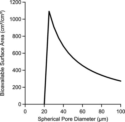
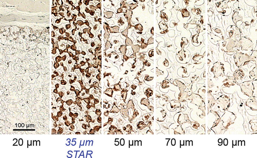
Fig. 22.5
Calculated bioavailable surface area for sphere-templated biomaterials as a function of the pore diameter. Note: calculations assume 40 % throat-pore size ratio, porosity of 65 %, 7.5 throats per pore, and 10-μm minimum throat size for cellular access [20]
Fig. 22.6
Tissue sections of sphere-templated scaffolds with a series of controlled pore sizes implanted subcutaneously in mice for 4 weeks, stained with F4/80 macrophage marker. The 35-μm pore size (STAR® Biomaterial) is infiltrated with the largest number of F4/80 positive cells
Beside the pore size, tight control of the pore throat diameter is also a critical parameter. On one hand, this dimension is on the same size scale as the macrophage cells (a human macrophage is 10–20 μm in diameter) [22]. To facilitate cellular infiltration, pore throats must therefore be at least ~10 μm in diameter. On the other hand, the throat-pore size ratio is constrained by practical considerations of the sphere-templated geometry: if the pore throat size is increased much beyond ~40 % of the spherical pore diameter, the neighboring pore throats within each pore would nearly overlap, and mechanical strength of the templated porous structure may fall off precipitously.
Maximized Vascularization
The STAR pore dimensions also encourage vascularization of the porous biomaterial with a robust capillary network. Figure 22.7 demonstrates that maximum blood vessel density occurs in the same “sweet spot” pore range of 25–35 μm and that the increased vascular density is observed not only within the pores but also in the capsule tissue immediately adjacent to the outer boundary of the porous implant [21]. The vascularizing effect mirroring the pore size dependent trend observed with macrophages suggests that the macrophages within the pores promote angiogenesis via the release of proangiogenic factors. The neovascularization effects of implanted porous biomaterials had been observed previously by other researchers [23, 24]. The precise dimensional control of the STAR® sphere-templating method allowed the optimum pore size for maximizing density of vascular ingrowth to be determined with greater accuracy. Since the method ensures all pores and pore throats in the structure are optimized in size, the localized proangiogenic effect is more pronounced.
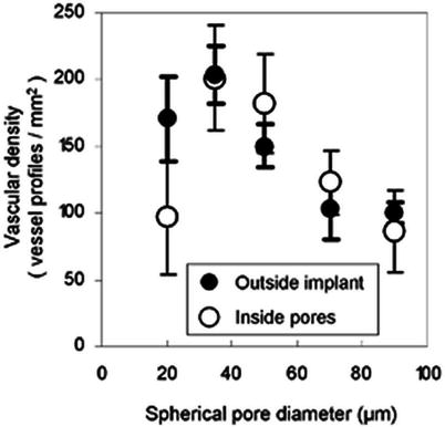
Fig. 22.7
In the “sweet spot” pore range around ~30 μm, the density of blood vessels is maximized both inside the implant and in the adjacent tissue within 50 μm of the implant. Vessels counted from sections of 4-week subcutaneous mouse implants stained with MECA-32 endothelial cell marker
The biointegration of STAR® Biomaterial was compared to expanded polytetrafluoroethylene (ePTFE) with 60-μm internodal distance – a porous biomaterial of similar pore size that has been investigated for glaucoma implants [25]. It was found that the STAR material induced a more smoothly integrated interface. As shown in Fig. 22.8, inflammatory cells accumulate in high concentration in the capsule tissue bordering the ePTFE implant, while the interface between the STAR® Biomaterial and the surrounding capsule tissue features a smooth transition in cellular density across the capsule-biomaterial boundary. Also, Fig. 22.9 shows that the endothelial cell concentration within the pores of STAR® Biomaterial was significantly greater than for ePTFE, indicating significantly increased intrapore neovascularization. The enhanced vascularizing effect compared to other porous biomaterials provided inspiration for the “STAR” acronym for sphere-templated angiogenic regeneration.
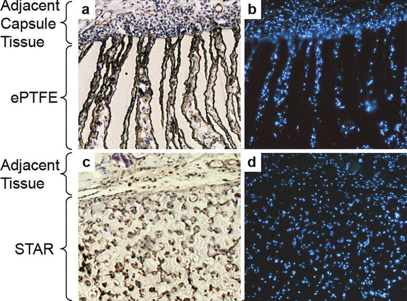
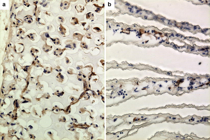
Fig. 22.8
Comparison of cellular integration at tissue-biomaterial interface for expanded polytetrafluoroethylene (ePTFE) (panels a and b) and STAR® Biomaterial (panels c and d). Tissue sections from scaffolds implanted subcutaneously in mice for 2 weeks, stained with MECA-32 brown endothelial marker (panels a and c) and with DAPI inflammatory cell nuclei marker (panel b and d). STAR material exhibits a more integrated interface with cells equally dispersed in scaffold and adjacent tissue while inflammatory cells accumulate and concentrate in adjacent capsule tissue around ePTFE implant (Used with permission of the authors and excerpted from [26])
Fig. 22.9
Comparison of level of vascularization within STAR® Biomaterial and expanded polytetrafluoroethylene (ePTFE). Tissue sections from scaffolds implanted subcutaneously in mice for 2 weeks, stained with MECA-32 brown endothelial marker. STAR scaffold (panel a) shows much higher level of neovascularization than ePTFE (panel b) (Used with permission of the authors and excerpted from [26])
It has been hypothesized that the increased neovascularization associated with STAR Biomaterial could be attributed in part to a shift in macrophage polarity triggered when the spatially confined macrophages within the pore structure are directed by geometric cues towards a proangiogenic phenotype [27].
Anti-fibrotic Properties
Severalfold reductions in foreign body capsule thickness compared to nonporous controls have been observed for STAR Biomaterial in a variety of small and large animal models [21, 27, 28]. In Fig. 22.10, implant made from STAR® Biomaterial elicits remarkably thinner and looser foreign body capsule compared to nonporous control of same size and shape in a porcine subcutaneous implant model [28].
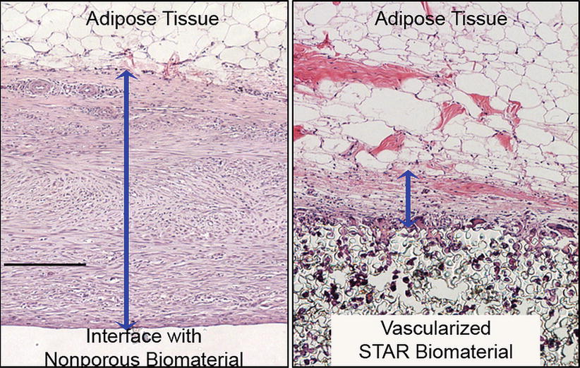
Fig. 22.10
H&E-stained tissue sections from 6-week subcutaneous porcine implants. Blue bands denote capsule thickness. The average thickness of capsules surrounding nonporous control implants (panel a) was nearly 4-fold greater than capsules surrounding STAR implants with 27-μm pore size (panel b). Black scale bar represents 200 μm
Although the mechanism for the reduction of peri-implant fibrosis is not fully understood, a plausible explanation is based on the idea that the vascularized tissue-biomaterial interface disrupts collagen lattice contraction. This “lattice slack” hypothesis is supported by a study where the capsule-reducing effects of STAR® Biomaterial were amplified by combining macrotopographic features and optimized microporosity in complementary configurations [28]. In that study, the absence of a myofibroblast layer in the capsule suggested a stress-relaxed condition with minimal fibrotic scar.
STAR Biomaterial’s high resistance to fibrotic scarring represents a tremendous advantage for the STARflo device over other types of GDDs where fibrosis is a recurring problem in the sustainability of IOP-lowering efficacy.
STARflo Glaucoma Implant
Of similar shape to the CELLplant device, the STARfloTM Glaucoma Implant is entirely made from silicone STAR® Biomaterial. Besides meeting the specific physical characteristics defined by Nordquist, this biomaterial exhibits advantageous inherent properties for a glaucoma drainage device:
The angiogenic properties are exploited by positioning the implant body in contact with the choroid, forming a well-integrated drain for the aqueous flow diffusing from the anterior chamber and minimizing the formation of a filtering bleb and its associated complication.
The biomaterial’s ability to reduce the thickness and density of the peri-implant fibrous capsule layer that forms during the course of the foreign body response may benefit longer-term pressure-lowering performance of the implant.
Material and Design
The STARflo device design is based on the previously mentioned patents. To overcome drawbacks associated with the cellulosic material of the CELLplant (e.g., long-term fibrosis and mechanical fragmentation), the STARflo device is made entirely from a long-term, implant silicone material (Nusil Technologies LLC, Carpinteria, USA) formed into the STAR structure. Silicones exhibit superior mechanical properties, durability, and reduced inflammation in ophthalmic implants [29]. The device is made as a single continuous sheet of porous silicone STAR scaffold free from seams, joints, coatings, metal, or degradable substances. Pore size and throat size within the material are uniformly 27 and 9 μm, respectively, through the entire volume of the device (Fig. 22.11) and comprised within the “sweet spot” pore range. The device has the same length and width, and general shape as the CELLplant predecessor, but a nominal thickness of 300 μm. In use, most of the body sits in the suprachoroidal space.
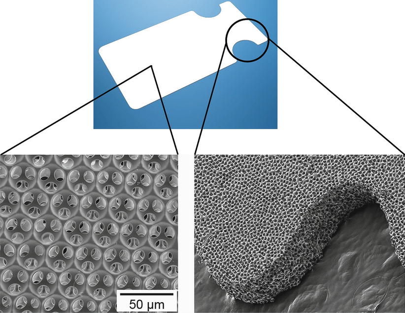
Fig. 22.11
SEM of the STARflo device entirely made of STAR® Biomaterial
The structure and pore dimensions of the STAR material forming the STARflo closely mimic those of the trabecular meshwork and the ~10-μm-sized natural drain openings into Schlemm’s canal, making the head section mimic the normal drainage path.
Intended Use and Implant Location
The STARflo device is indicated for open-angle glaucoma. Implantation can be made in any location around the circumference of the globe providing that the rectus muscles are avoided. For ease of access and technical performance of the surgery, upper quadrants are the most commonly chosen location (1–2 o’clock (OS) or 10–11 o’clock (OD)).
Since the implant is entirely made from very soft porous silicone, the head area may be folded for ease of insertion to the anterior chamber via a small incision, just sufficient to retain the device neck. The anterior portion of the body then rests under a tight scleral flap while the posterior portion of the body is placed between the sclera and choroid (Fig. 22.12). This configuration provides a controlled fluid path for aqueous humor to drain from the anterior chamber to the suprachoroidal space of the eye. The implant bypasses the obstructed normal outflow passages and reduces the IOP without the need of a filtering conjunctival bleb prone to numerous complications. It also may spare patients wound healing issues associated with filtering surgery.
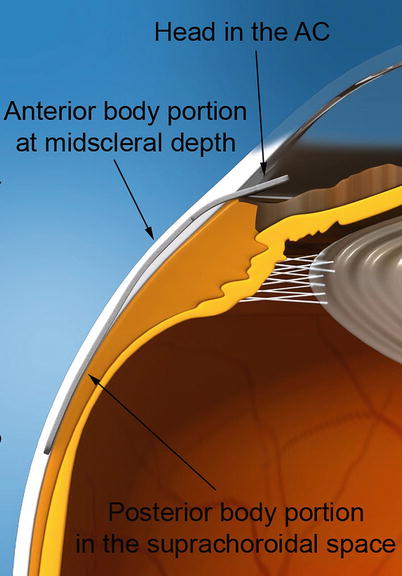
Fig. 22.12
Illustration of the anatomical placement of the STARflo device. The head of the implant is inserted in the anterior chamber, the anterior portion of the body rests under a scleral flap, and the posterior portion of the body is placed within the suprachoroidal space
Surgical Procedure
The device is designed to be surgically placed in an ab externo fashion, under local retro- or parabulbar anesthesia. Because of its anti-fibrotic properties, STARflo implantation does not require the use of anti-fibrotic agents such as mitomycin C (MMC) or 5-fluorouracil (5-FU). The surgical implantation procedure recommended by iSTAR Medical is animated in Video 22.1, although the choice of anesthesia and method or technique to implant the drainage device is upon surgeon discretion.
A fornix-based conjunctival peritomy is first created, followed by a superficial, rectangular scleral flap (50 % thick, 8 mm wide, 3 mm long) as depicted in Fig. 22.13a. The second layer of sclera is then cautiously incised to reveal the choroid tissue, parallel to the limbus and leaving a scleral bridge of 1–2 mm (Fig. 22.13b). A 3-mm-wide incision is performed to reach the anterior chamber through the trabecular meshwork and allows STARflo head to be introduced (Fig. 22.13c). A subscleral pocket is then created by separating the sclera from the choroid using a blunt spatula. The posterior aspect of the implant is gently guided into the suprachoroidal space (Fig. 22.13d). One corner of the STARflo head is then inserted into the anterior chamber through the previously created entry at the level of the scleral spur, followed by the other corner (Fig. 22.13e). When correctly placed, the implant neck is centered in the 3 mm incision and lays flat on the sclera without folds. The implant head is parallel to the iris to avoid incarceration or shunt-to-cornea touch and endothelial trauma. The scleral incision is then closed in a watertight fashion to avoid bleb formation. Finally, conjunctiva is sutured watertight. At all times, it is recommended to keep the implant moist using viscoelastic or sterile saline solution as a dry implant might compromise device performances. The use of non-toothed, blunt forceps is also recommended as well as avoidance of grasping the implant body.
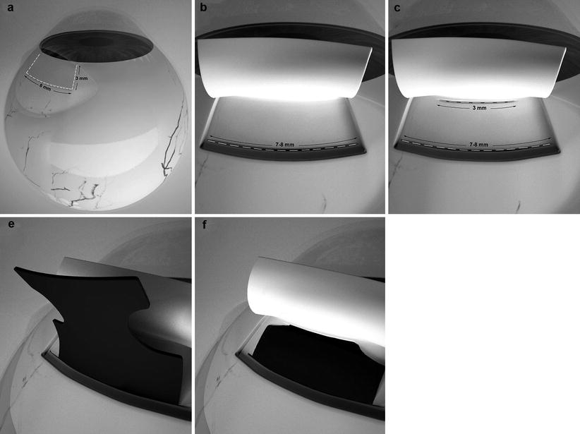
Fig. 22.13


Key sequences of the STARflo surgical procedure recommended by iSTAR Medical SA. A half-thickness scleral flap (8 mm wide, 3 mm long) is performed (panel a) followed by a posterior full-thickness scleral incision (panel b). A 3-mm-wide entry is created into the anterior chamber (panel c). Body implant is guided into the suprachoroidal space (panel d) while the head of the implant is inserted into the anterior chamber (panel e)
Stay updated, free articles. Join our Telegram channel
Full access? Get Clinical Tree
