Spectacle Lens Powers
Gregory L. Stephens
Darryl J. Meister1
The authors would like to acknowledge the contributions of the late John K. Davis to chapters 51 A-D. John was an author of previous versions of these chapters and his ideas have heavily influenced the present version.
The primary goal of a refractive examination is to discover the lens power that results in a sharp image of a distant object being formed on a patient’s retina when the patient is not accommodating. There may be other requirements, such as a need for clear vision when reading or when performing occupational tasks, but in this chapter we are concerned only with distance vision. With a correcting lens in position, parallel rays from a distant object entering the spectacle lens are either converged or diverged to compensate for the patient’s refractive error. The patient is then able to see distant objects clearly and can accommodate or use multifocal lenses to see objects at other distances.
The word parallel is used in this chapter to describe a bundle or group of light rays coming from a single point on a sufficiently distant object. If an eye with a 7-mm diameter pupil looks at a road sign 100 m away, the bundle of rays that enter the eye from any single point on the sign have diverged only 4/1,000 of a degree, so we call them parallel. In a refracting room, the bundle of rays from a single point on a letter on the visual acuity chart is not quite parallel. At 6 meters (20 feet), which is considered to be optical infinity for the purposes of a refraction, the light rays have a divergent power of -1/6 = -0.16 diopters (D), as they enter the refractor. At 3 meters (10 feet), the light rays diverge -0.33 D. Some practitioners adjust for this factor when they determine the spectacle prescription.
Precision of the Refraction
The precision of a refraction is limited in part by the sensitivity of the patient to small changes in lens power. For most observers, 0.25 (¼) D represents the smallest discernible or “just noticeable” difference in prescription sphere or cylinder power, so refractor and trial set lenses are provided in increments of 0.25 D. Consequently, the refraction may be in error by up to 0.13 (1/S) D – or ½ of 0.25 D – in either direction for a given patient. The ANSI Z80.1-2005 standard for prescription ophthalmic lenses in dress eyewear recommends that spectacles be made to an accuracy of 0.13 (1/S) D for most prescription powers.1 This ensures that the difference between the exact refraction required by the patient and the final power of the prescription lens remains within the just noticeable difference threshold of the patient, even in the presence of the maximum fabrication and refraction errors. An auxiliary lens with a power of 0.13 D is available in most refractors and trial lens sets for use with the occasional patient who can notice this small power change, and it is possible to order lenses in 1/S D steps when necessary.
The accuracy with which a patient can position the cylinder axis during a refraction is determined in large part by the cylinder magnitude. When a refractor cylinder lens has the proper power but is positioned at the wrong axis, the axis error creates unwanted cylinder power with an axis that is 45 degrees away from halfway between the correct and incorrect cylinder axis values.2 For example, if a patient needs 2.00 D of cylinder axis 90, but the refractor cylinder axis is positioned at an axis of 84 degrees, then unwanted cylinder power will be created at an axis of 132 degrees or 42 degrees (87 degrees, which is halfway between 90 and 84 degrees, ± 45 degrees). The power of this unwanted cylinder depends upon both the amount of cylinder axis misalignment and the refractor cylinder power. If this unwanted cylinder power is above the patient’s threshold for detecting blur, then the patient will be able to notice the axis error during the refraction. Figure 1 illustrates how cylinder axis positioning accuracy varies with cylinder power, using the assumption that a patient will be able to notice 0.25 D of unwanted cylinder power. For low cylinder powers, a large cylinder axis error is needed to generate 0.25 D of unwanted cylinder power, so a patient is unlikely to be sensitive to a small axis error. However, for a 3.00 D cylinder, an axis misalignment of only about 2 degrees creates 0.25 D of unwanted cylinder. So, in general, as cylinder power increases, a patient’s tolerance for cylinder axis error decreases. Tolerances in the ANSI Z80.1-2005 dress ophthalmic lens standard are also based upon this type of analysis, but with the requirement that cylinder axis errors occurring in the manufacture of a spectacle lens should not create more than 1/S D of unwanted cylinder power.3,4 Optical laboratories therefore are expected to position the axes of larger cylinders more accurately than for smaller cylinders.
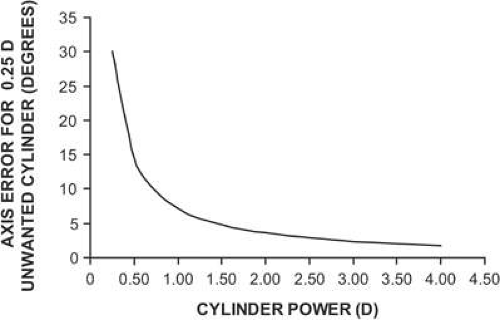 Figure 1. Cylinder axis location error that creates 0.25 D of unwanted cylinder power when the cylinder axis is mislocated during a refraction. As cylinder power increases, less axis error is needed to create 0.25 D of unwanted cylinder. Patients with large amounts of astigmatism tend to be more sensitive to axis positioning errors than patients needing smaller astigmatic corrections. |
Myopia, Hyperopia, and Astigmatism
When an uncorrected myope looks at a distant object with accommodation relaxed, parallel light rays entering the eye form an image in front of the retina (Fig. 2). The eye has either too much plus power, or the eye is too long. For the in-focus image to fall on the retina, the light entering the eye must be made divergent. There are two ways to accomplish this objective. One, the object may be moved closer to the eye so that the object itself becomes a source of divergent light. The object position at which light from the object forms a focused image on the retina with accommodation fully relaxed is the patient’s far point (punctum remotum). Alternatively, if the object is to remain far away, at some optically infinite distance, a divergent (minus power) lens may be placed in front of the eye to correct the refractive error. When the lens has the proper power, its secondary focal point (the point at which incident parallel light is focused) falls at the patient’s far point, and parallel light from the object is diverged so that it appears to originate from the patient’s far point. In the terminology of geometric optics, the lens forms a virtual image of the distant object at the patient’s far point. This image becomes the new object for the eye, which subsequently converges the light to form the image on the retina.
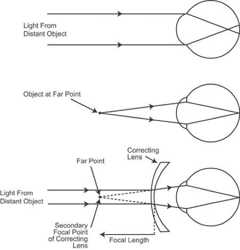 Figure 2. Optical correction of myopia. Light from a distant object focuses in front of the retina of the uncorrected eye, creating a blur circle on the retina. For the in-focus image to fall on the retina, the object must be placed at the far point of the eye. Alternatively, a minus-power correcting lens may be placed in front of the eye to provide divergent light that simulates light coming from a near object. The secondary focal point of the correcting lens falls at the far point of the eye. |
An analogous situation occurs for the uncorrected hyperope (Fig. 3). When the patient views a distant object without accommodating, the image falls behind the retina. Placing an image on the retina requires convergent light, a situation that cannot be achieved by moving a real object, but only with a lens or with accommodation. A plus-power lens placed in front of the eye converges the parallel light rays. This convergent light is further converged by the cornea and lens to form a retinal image. Unlike the situation for the myope, the far point of the hyperope is a virtual point behind the retina. A convex lens converges light from the distant object toward the far point so that the final image is formed by the eye on the retina. A young hyperope can use accommodation instead of a correcting lens to bring the image forward onto the retina, although the convergence associated with this accommodative effort may result in binocular dysfunction in some cases. The patient may not seek a refractive correction until he or she gets older and begins to lose accommodative ability or until prolonged near work causes fatigue because of the sustained accommodation required.
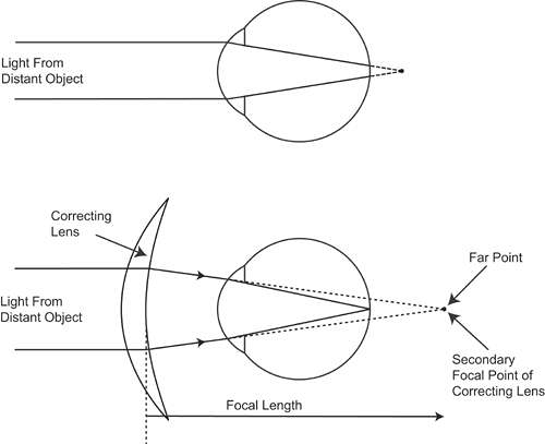 Figure 3. Optical correction of hyperopia. Light from a distant object focuses behind the retina of the uncorrected eye. The secondary focal point of the plus-power correcting lens must fall at the far point to correct the hyperopia. |
When a patient with astigmatism views a distant object point without accommodating, the point is imaged as two lines oriented 90 degrees apart (Fig. 4). In essence, the astigmatic eye has two different far points. (The astigmatism may be combined with either hyperopia or myopia.) Correction of the patient’s refractive error now requires a lens that forms two different images, one at each of the far points. Such a lens has two different powers and is termed a spherocylindrical, or spherocylinder, lens to distinguish it from a spherical, or sphere, lens, which corrects only myopia or hyperopia. With the proper spherocylinder lens in position, the distant object point can be focused as a single point image on the retina.
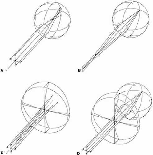 Figure 4. Optical correction of astigmatism. A. Light from a distant point object is focused at two different positions by the astigmatic eye. The image at each position is a line. B. The astigmatic eye has two far points, one for each principal meridian. For this myopic eye, the far points are in front of the eye. C. A spectacle lens that corrects astigmatism has two focal points. D. When the focal points of the correcting lens coincide with the far points of the astigmatic eye, the refractive error is corrected. |
Lens Surface Power
The power of a spectacle lens is determined in large part by the powers of its front and back surfaces. The power of a lens surface is given by:
where F is the surface power in diopters, n is the index of refraction of the medium containing the incident light (the light before refraction), n’ is the index of the medium containing the refracted light, and r is the radius of curvature of the surface, specified as the distance from the surface to its center of curvature, measured in meters. A sign convention simplifies specification of powers and radii. One commonly used convention is to specify distances relative to the direction of travel of light. In this chapter, light is always considered to be traveling from left to right. If a distance is measured in the same direction as the direction of travel of light, then the distance is positive. If it is measured in the opposite direction of light, the distance is negative. An example is shown in Figure 5. With light traveling from left to right, the distance from A1 to C1 (r1) and the distance from A2 to C2 (r2) are both positive. The index of refraction of the lens is always greater than 1.0, so the front surface power (F1) for this example is positive and the back surface power (F2) is negative. This is the typical surface power relationship for most spectacle lenses. Such a lens is known as a meniscus lens.
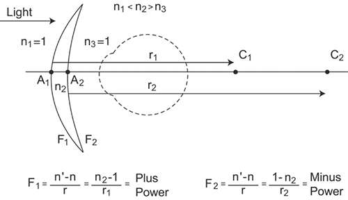 Figure 5. A sign convention for lens surface power and radius of curvature. C1 and C2 are the centers of curvature of the front and back surfaces, respectively, of this meniscus lens. The points A1 and A2 mark the positions of each surface. The index of refraction of the lens is n2, while n1 and n3 are the indices surrounding the lens (usually air with an index of 1.0). The distances measured from A1 to C1 and from A2 to C2 (the radii of curvature) are both positive because both are measured in the direction of the incident light. As a result of this sign convention, the lens front surface has a plus power, and the back surface has a minus power. |
The Lens Clock
Lens surface powers are measured using a lens clock or lens measure (Fig. 6). When placed against a curved surface, the middle of the three lens clock pegs moves up or down, measuring the sagittal depth of the curve delineated by the two outer pegs. This sagitta will be related to the radius of curvature of the surface. Surface power can then be calculated from the radius using equation 1. Equation 1 requires that a value for the index of refraction of the lens be chosen, and the value assumed for lens clock dials is 1.53. Although most lens materials have an index different from 1.53, this index serves as a standardized “tooling” index for the purpose of measuring physical curvature or radius of curvature (as opposed to surface power). Because the refractive indices of most common lens materials range from 1.50 to 1.60, a tooling index of 1.53 allows for a fairly accurate estimation of the refractive powers of the surfaces of most lenses. Nevertheless, the actual refracting power of a surface will typically be higher (for high-index lenses) or lower (for crown glass and CR-39 plastic lenses) than the value indicated by the lens clock.
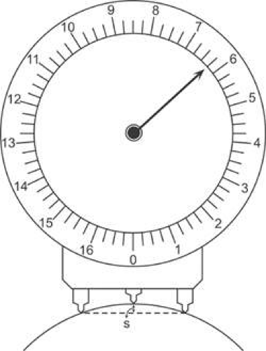 Figure 6. A lens clock measures surface power by determining the sagittal depth, s, of a surface. Sagittal depth can be converted to radius of curvature, then to surface power using an assumed index of refraction of 1.53. For this example, the measured surface power is +6.25 D. |
When assuming an index of 1.53 to specify the power of a lens surface, optical laboratories and lens manufacturers are, in essence, specifying the surface by its physical curvature. The practice of specifying exact 1.53 powers for the curves of spectacle lenses means that manufacturers and optical laboratories can use one set of surfacing tools (standardized to an index of 1.53) to grind the surface curves and a single gauge (calibrated for an index of 1.53) to measure the accuracy of these curves for all lenses, regardless of the actual index of the lens material.
A simple equation converts the power of a lens surface as measured by a lens clock to the actual refractive power of the surface, as follows:
where Frefractive is the actual refracting power of the surface, FLC is the value as read by the lens clock (the 1.53-based power), and nlens is the index of refraction of the lens material. As an example, a lens made of polycarbonate plastic of index 1.586 with a 1.53 front surface power of +5.00 D as measured by a lens clock has an actual front surface refractive power of +5.00 × (0.586/0.53) = +5.53 D. As a general rule, only optical laboratories and lens manufacturers need to know the actual refracting power of lens surfaces. Eyecare practitioners specify lens surface powers by the 1.53-based power, the power as read by the lens clock.
The Base Curve
The clinician rarely specifies lens surface powers when writing a spectacle prescription because optical laboratory personnel usually choose the surface powers based on the recommendations of lens designers. However, in certain cases, such as when providing a second or replacement pair of spectacles to a patient, when a patient is having trouble adapting to a prescription change, or when magnification effects are of concern, the practitioner may want to order a specific surface power or curve as part of the prescription. By convention, the surface power ordered is termed the base curve. The base curve is the reference curve that is the base or basis from which all other surface powers are calculated. For most lenses, the base curve is defined as the power of the lens front surface. This is typically the factory-finished surface. Most commonly, base curves are expressed using 1.53-based power, meaning that the base curve will match the value read by the lens clock, not the actual refracting power of the surface. Once the base curve of a lens, its power, and its thickness are specified, both of the lens surface powers are completely defined. There can be only one way for the optical laboratory to make the lens.
Stay updated, free articles. Join our Telegram channel

Full access? Get Clinical Tree


