Principles in Rigid Fixation of the Facial Skeleton
Robert M. Kellman
Sherard A. Tatum
In this age of rapid transportation and increasing urban violence, severe facial trauma is an entity that the otolaryngologist -head and neck surgeon is likely to encounter. Complex facial trauma may refer to blunt and/or penetrating trauma resulting in multiple facial fractures and varying degrees of soft tissue injury or loss.
Skeletal facial trauma is frequently subdivided into fractures of the frontal sinus, nasoethmoid complex, zygomaticomaxillary complex, midface, dentoalveolar structures, mandible, and other unusual fracture patterns. Complex facial trauma can then refer to either the multiplicity of areas involved (i.e., panfacial fractures) or the degree of severity of involvement of a given area. For purposes of this chapter, massive facial trauma refers to high-energy blunt or penetrating trauma leading to severe bony displacement, comminution or frank bone loss, and/or involvement of multiple anatomic areas and reducing the availability of anatomic reference points for fracture reduction. These injuries may be associated with severe soft tissue lacerations, avulsions, or globe or central nervous system injuries. Regardless of the precise definition of massive facial trauma, it is our contention that these injuries can be managed successfully by adherence to the same basic principles that lead to successful outcomes from less complex trauma.
BONE HEALING
Bone is a complex tissue made up of a collagen matrix mineralized with calcium phosphate (hydroxyapatite) crystals. Interspersed within bone are cellular components that mediate bone resorption, deposition, and metabolism. Thicker areas of bone typically involve two structural components: an outer cortical or dense bone layer and an inner cancellous or spongy bone layer. Thinner sections of bone are lamellar and lack significant cancellous bone or marrow space. Nutrition is supplied to bone through the outer layer of periosteum and inner open circulation of the marrow space (1).
Fracture results in disruption of the bone matrix, surrounding soft tissue and, if applicable, marrow space. This disruption allows blood and inflammatory cells to flood the area. A hematoma forms, which matures through granulation tissue, fibrous tissue, cartilage, and then bone or directly from fibrous tissue to bone depending on the embryologic origin. This callous formation allows indirect healing to occur when the edges of the bone are not approximated. Mineralization eventually occurs if motion is not excessive. If not anatomically reduced, segments heal in a new position, which may lead to deformity and dysfunction (2).
If the distance between bone fragments is decreased by anatomic reduction of the fracture, then healing will occur with less callous formation and diminished alteration of anatomy. Areas of the fracture that are abutted and compressed will heal by contact healing or direct osseous formation without significant callous formation. Direct osseous healing is not likely to occur along the full length of a fracture even if it is well reduced. Microgaps heal by callous formation or gap healing in which bone is laid down directly perpendicular to its normal orientation followed by remodeling to change this orientation. Regardless, the fragments heal in anatomic position (3).
Problems with the bone-healing mechanism can lead to clinical complications of fractures. Delayed union refers to reduced or absent mineralization of a fracture line 8 to 12 weeks after immobilization. Malunion occurs when a fracture heals by osseous union with segments in nonanatomic position. Fibrous union occurs when progression of indirect healing to ossification does not occur. A nonunion can refer to fibrous union, although it typically connotes a wider gap with very poor function, whereas fibrous unions may not result in a functional deficit. Pseudoarthrosis refers to a fibrous union that is mobile enough to function
like a joint. This phenomenon might be a desirable result for a subcondylar fracture that has resulted in temporomandibular joint ankylosis. Otherwise the mobility leads to dysfunction and pain. Inadequate stabilization and infection are major causes of these healing problems (4).
like a joint. This phenomenon might be a desirable result for a subcondylar fracture that has resulted in temporomandibular joint ankylosis. Otherwise the mobility leads to dysfunction and pain. Inadequate stabilization and infection are major causes of these healing problems (4).
FRACTURE PATHOPHYSIOLOGY AND CLASSIFICATION
Fractures occur when forces are applied that exceed the stress capabilities of bone, leading to a disruption of the mineralized matrix with additional disruption of the associated soft tissue. Fractures may be simple, involving a single disruption between two bone segments, or comminuted, meaning multiple bony fragments exist in the separation between bone segments. Displacement refers to the alteration in anatomic relationships of bony segments. This alteration can occur as a result of the energy of the blow itself or because of unopposed muscle pull. Angulation is the change in angle of the long axis of the bone across the fracture. Distraction refers to the distance between bone segments across a fracture, and rotation is the orientation alteration of bone segments along their long axis. A fracture is considered favorable if it is oriented such that muscle pull vectors act to compress the fracture. An unfavorable fracture is one oriented such that muscle pull vectors act to displace the fragments (Fig. 78.1).
The concept of open or compound fractures relates to the exposure of fractured bone outside the soft tissue, leading to bacterial contamination. This idea is a little confusing in the face because of the oral, nasal, and sinus cavities. Certainly, fractures involving gross lacerations of facial skin or oral mucosa exposing bone are open fractures. Typically, fractures involving tooth-bearing bone even without mucosal laceration are considered open because of exposure to the oral flora through the periodontal tissue. Fractures through the nasal cavity involving mucosal lacerations are likewise exposed to nasal flora. Fractures through an uninfected sinus cavity may not initially involve bacterial contamination; however, a blood-filled sinus is likely to become colonized fairly quickly. Therefore, few facial fractures would not be considered open. Isolated mandibular ramus or subcondylar fractures and zygomatic arch fractures are among these.
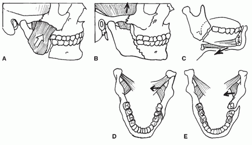 Figure 78.1 A: Posterior body fracture with unfavorable angulation. Pull of masseter muscle distracts fracture. B: Favorable posterior body fracture. Pull of temporalis muscle compresses fracture. C: Unfavorable fracture. Pull of hyomandibular musculature distracts fracture. D: Favorable fracture orientation. Pterygoid musculature compresses fracture. E: Unfavorable fracture orientation. Pterygoid musculature distracts fracture. |
The amount of energy associated with the injury tends to affect the characteristics of the injury. Low-energy impacts such as fist blows tend to lead to less comminuted and less displaced fractures. High-energy impacts are more typically associated with comminution, greater displacement, and a greater degree of soft tissue injury. The rate of energy dissipation into the tissue is the true determinant. A hard object striking the face is more likely to lead to comminution than a fist striking with the same energy because the energy of the blow is transferred to the tissue more quickly. The kinetic energy of the object may be greater as well. Penetrating trauma is similar, with low-energy missiles creating less injury than high-energy missiles. However, missile design comes into consideration. A high-energy missile with a hard surface may exit the body fairly quickly, not dissipating all its energy into the body. A lower-energy missile designed to expand, spiral, or tumble and dissipate most of its energy before exit can be more damaging. However, the amount of shock wave energy from the missile impact determines the degree of collateral tissue damage. Pointblank gunshot wounds have the added soft tissue injury of the expanding propellant gases. This blast injury can lead to poor healing, infection, and fibrosis. Ballistics information is helpful, but wound evaluation is still the best guide (5).
RATIONALE FOR RIGID FIXATION
Regardless of the etiology or classification of the fracture, the healing mechanism can be assisted with reapproximation of the fragments followed by fixation to create stability and reduce movement of the bone fragments. Decreasing
movement of the bone fragments enhances ossification and the progression to a bony union. Reestablishment of blood supply to devascularized bone fragments or bone grafts is also enhanced by immobility. This lack of movement or stability requires overcoming the biomechanical forces acting on the bone fragments. Varying degrees of stability are imparted by different fixation techniques. Rigid fixation of fractures with plates and screws is thought to provide superior stability by overcoming functional forces applied by the musculoskeletal system across a fracture (6). This concept is not universally accepted, however. Enhancements in imaging capabilities and surgical exposure techniques and a greater interest in maxillofacial trauma have paralleled the development of plating technology. These developments may account for improved trauma outcomes. Additionally, plates have been criticized for being palpable, occasionally being visible, causing temperature sensitivity, inhibiting growth, and weakening bone by stress shielding. Some of these criticisms are more theoretic than others, but absorbable plating systems promise to alleviate most of these problems. To obtain comparable strength, characteristics of absorbable plating systems currently require larger plates and screws than their metal counterparts, so they are not suitable for every indication. However, newer reinforced materials may alleviate this problem (7, 8).
movement of the bone fragments enhances ossification and the progression to a bony union. Reestablishment of blood supply to devascularized bone fragments or bone grafts is also enhanced by immobility. This lack of movement or stability requires overcoming the biomechanical forces acting on the bone fragments. Varying degrees of stability are imparted by different fixation techniques. Rigid fixation of fractures with plates and screws is thought to provide superior stability by overcoming functional forces applied by the musculoskeletal system across a fracture (6). This concept is not universally accepted, however. Enhancements in imaging capabilities and surgical exposure techniques and a greater interest in maxillofacial trauma have paralleled the development of plating technology. These developments may account for improved trauma outcomes. Additionally, plates have been criticized for being palpable, occasionally being visible, causing temperature sensitivity, inhibiting growth, and weakening bone by stress shielding. Some of these criticisms are more theoretic than others, but absorbable plating systems promise to alleviate most of these problems. To obtain comparable strength, characteristics of absorbable plating systems currently require larger plates and screws than their metal counterparts, so they are not suitable for every indication. However, newer reinforced materials may alleviate this problem (7, 8).
BASIC PRINCIPLES OF RIGID FIXATION
The central concept of rigid fixation is to return skeletal fragments to their anatomic position and rigidly fixate them in that position with an implantable device that provides sufficient strength across the fracture to maintain the reduction against musculoskeletal forces. Fixation plates are designed to span a fracture and provide stress shielding and fracture stability. The plates are fixed to the bone with screws. Each screw placed in the bone is a fixation point. Larger plates made of stiffer material provide greater stress shielding and stability. Large screws provide stronger fixation than small screws. Bicortical screws provide greater stability than monocortical screws, and increasing the number of screws or fixation points anchoring a plate to a bone segment increases stability. Compression or loading of the bone across the fracture enhances stability by increasing the friction between the fracture edges (9). Additionally, plate location relative to bone thickness and the many complex forces acting on the bone are important. Generally speaking, greater bone thickness is found when the forces acting on the bone are greater; however, more bone thickness allows for longer screws, providing increased stability. Forces acting to angulate a fracture distract one end of a fracture and compress the other. A plate placed closer to the end being distracted is more likely to overcome those forces than a plate located at the end being compressed because of mechanical advantage related to the lever principle (Fig. 78.2).
The previous statements are true within certain limitations. The more rigid a plate is, the more precise the bending of the plate has to be to conform to the surface contours of the bone where it is to be applied. Otherwise, as the screws are tightened, the bone may be pulled toward the plate, creating distraction (Fig. 78.3). To overcome this problem, locking-screw plates have been developed. These allow the threaded screw head to lock into a corresponding threaded plate hole, so the screw head locks to plate. This obviates the need for the preciseness of the bend, because the bone will not be pulled to the plate. In mandibular repair, monocortical miniplates have been found to be adequate to replace a heavy bicortical plate so long as they are properly positioned to overcome the distracting forces that occur during function (10). Additional fixation points (i.e., screws) provide additional stability; however, the incremental increase in stability decreases as the number of fixation points increases (11). The increase in stability must be weighed against the additional exposure required and higher bulk of the larger implant. Increasing screw diameter must be weighed against the weakening of the residual bony buttress created by increasing the screw hole size. Increasing screw length into cancellous bone adds little additional strength unless a second cortex is engaged. Screw length beyond the applicable bone thickness certainly adds no strength, and damage to underlying structures such as tooth roots could occur.
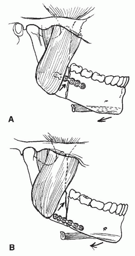 Figure 78.2 Muscle pull distracts superior border of fracture and compresses inferior border of fracture. Plate placement in (A) prevents superior distraction. Plate placement in (B) does not. |
FIXATION DEVICE CLASSIFICATION AND TERMINOLOGY
The terminology applied to plating systems is confusing and nonuniform, because it is applied differently by different manufacturers. Plating systems are usually identified
either by their dimensions or by their application. The term miniplate typically refers to plates designed for screws in the 1.2- to 2.5-mm range. The term microplate refers to plates designed for screw diameters around 1 mm. There are several intermediate sizes and now modular systems with multiple plate and screw dimensions. Larger systems are designed specifically for the mandible with screw diameters up to 2.4 mm or more and greater lengths for bicortical applications, including lengths up to 40 mm for lag screw applications. Usually, as screw size increases, so does plate thickness. So-called three-dimensional (3-D) plates are available in mini and micro sizes. These plates have added strength due to a lattice design (12).
either by their dimensions or by their application. The term miniplate typically refers to plates designed for screws in the 1.2- to 2.5-mm range. The term microplate refers to plates designed for screw diameters around 1 mm. There are several intermediate sizes and now modular systems with multiple plate and screw dimensions. Larger systems are designed specifically for the mandible with screw diameters up to 2.4 mm or more and greater lengths for bicortical applications, including lengths up to 40 mm for lag screw applications. Usually, as screw size increases, so does plate thickness. So-called three-dimensional (3-D) plates are available in mini and micro sizes. These plates have added strength due to a lattice design (12).
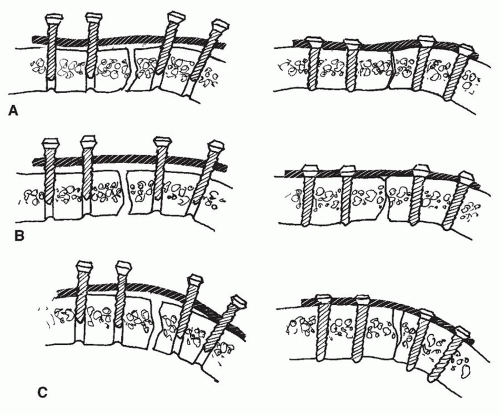 Figure 78.3 A: Plate is bent to appropriate contour with bony cortex so that when screws are tightened, lingual and buccal cortices are approximated. B: Plate is underbent, approximating buccal cortex but distracting lingual cortex. C: Plate is overbent, approximating lingual cortex but distracting buccal cortex. |
Plating systems are sometimes designated according to their proposed function, such as maxillary or zygomatic miniplates or mandibular miniplates. Although screw dimensions may be the same, mandibular miniplates are thicker than maxillary and zygomatic miniplates. Mandibular miniplates are typically 1 mm thick. Mandibular systems are further delineated as trauma sets or reconstruction sets, with the reconstruction sets offering the thickest (3 mm or more) stiffest plates in the greatest lengths and with the largest screws. Condylar prostheses may be included. Specialty plates also exist that are prebent for orthognathic surgery or with special configurations useful for microvascular reconstruction of the mandible. Various mesh designs are used to replace defect areas in non-load-bearing areas such as the orbital floor. Newer orbital floor plares have been designed from human models to mimic the anatomical contours (convexities and concavities) of the orbital floor and medial wall providing for more precise repairs.
Dynamic compression plates are designed to push fracture fragments together as the screws are driven. The plate holes are ovoid, and the edges of the hole are slanted. The holes for the screws are drilled eccentrically within the plate holes so that when the screw is tightened, the head slides down the slant, bringing the bone with it. The plate hole orientation determines the direction of movement and compression. Standard dynamic compression plates compress parallel to the plate across the fracture. Eccentric dynamic compression plates have holes on the end that are oriented to provide angular compression for the superior border of the mandible. Today, compression plates are used less frequently than in the past, and eccentric dynamic compression plates are rarely used.
Absorbable plates and screws can be used as well, though to obtain strengths similar to titanium, larger implants are required (13).
PRINCIPLES OF SCREW APPLICATION
For a screw placed in bone to serve as a stable fixation point, the threads of the screw must engage or grip the bone around the drill hole. Factors leading to inherent bone weakness such as osteoporosis or osteitis are beyond the surgeon’s control. Adherence to good surgical technique, however, will enhance the stability of the screw in the bone. The drill hole must match the inner screw shaft diameter. If the hole is too small, excessive friction and stress will result. This excess can lead to shearing of the screw head or local bone ischemia and resorption. The screw is held by a functional sleeve of bone around the drill hole that is the thickness of the screw threads (Fig. 78.4). This thickness varies from screw to screw but is typically on the order of 0.1 to 1.0 mm. Any imprecision in drilling can lead to reduction of this sleeve of bone and a larger than desired drill hole. High-speed drill chatter, bent drill bits, drill angulation
change (i.e., hand movement), or continued drilling once the hole is complete can lead to attrition of the bone around the drill hole. Excessive heat leads to delayed attrition from osteocyte death. Therefore, ideal drilling is achieved with a sharp straight drill bit, a low-speed drill, a drill guide, a steady hand, and copious irrigation. The diameter of the drill bit should match the diameter of the screw shaft without threads, not the diameter with threads. If a drill bit’s diameter matches the screw’s outer diameter with threads, then the screw can be pushed or pulled through the drill hole without turning the screw. This situation is termed gliding and is desirable only in lag screwing.
change (i.e., hand movement), or continued drilling once the hole is complete can lead to attrition of the bone around the drill hole. Excessive heat leads to delayed attrition from osteocyte death. Therefore, ideal drilling is achieved with a sharp straight drill bit, a low-speed drill, a drill guide, a steady hand, and copious irrigation. The diameter of the drill bit should match the diameter of the screw shaft without threads, not the diameter with threads. If a drill bit’s diameter matches the screw’s outer diameter with threads, then the screw can be pushed or pulled through the drill hole without turning the screw. This situation is termed gliding and is desirable only in lag screwing.
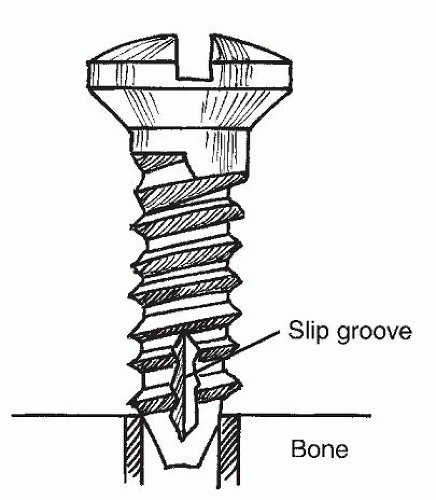 Figure 78.4 Detail of fixation screw in bone. The diameter of the hole in the bone matches the inner core diameter of the screw, not the outer thread diameter of the screw. |
Tapping refers to the cutting of screw threads in the drill hole. Most systems now have self-tapping screws that have flutes beginning at the tip of the screw and extending several threads up the screw to allow for the cutting of the bone into a thread pattern. Residual bone dust from the drilling should be irrigated away from the hole before screw application. The act of tapping itself creates additional bone dust as the threads are cut. This material can lead to binding and excessive wear of the threads. The bone dust should be released by intermittent back turns while tapping and irrigated away. Some systems require or offer as an option tapping as a separate step. The tap thread must match the screw threads exactly, and the subsequent screw must be placed carefully to avoid cross-threading. If inadequate bone exists around the drill hole to hold the screw, then it will fail to tighten as it is screwed into the bone and will begin to slip. Overtightening of the screw can lead to microfracture or stripping of the bone threads as well. Because this is a fairly frequent occurrence, most plating systems contain emergency (rescue) screws, which are screws with the same shaft diameter but a greater thread diameter to allow for bone engagement beyond the stripped portion of the hole. If the emergency screw fails to engage, then another fixation site must be sought. If the plate has extra holes beyond what is needed for adequate fixation, the stripped screw or “spinner” may still be useful. That screw can be left in to anchor the reduction and plate position until the other screws are placed. Then it should be removed and when possible replaced with a larger screw. An advance in screw design eliminates the need for drilling. The tip of the screw is like a drill bit, and the screw is driven directly into the bone. Self-drilling screws allow placement of the screws directly into the bone, avoiding drilling altogether. These are especially helpful in thin bone.
LAG SCREW APPLICATION
A lag screw presses two pieces of bone together by compressing the first piece of bone between the second piece in which the tip of the screw is engaged and the head of the screw (Fig. 78.5). In this situation, a hole is drilled relatively perpendicular to a fracture line traversing the fracture. The hole is double drilled such that the part of the hole on the screw head side of the fracture matches the diameter of the screw with threads, allowing the screw to glide or to be pushed through the hole to the fracture. On the other side of the fracture, the hole diameter is drilled to match the screw shaft diameter without threads. This allows the screw threads to engage the bone on the other side of the fracture. As the screw is tightened, the top fragment is compressed between the head of the screw and the second fragment in which the threads are engaging on the other side of the fracture. An enhancement of this technique has occurred through the development of a tapered drill bit. This bit allows a single drilling motion to provide a larger gliding hole on the screw head side of this fracture and a smaller engaging hole on the other side of the fracture. Because of the often near-tangential angulation of the screw relative to the cortical surface, a countersink hole is drilled to allow the screw head to seat better. Sometimes, drilling the countersink hole first facilitates drilling for the lag screw. The countersink hole should not be too deep or the screw head as it is tightened will pull through the residual cortex into the marrow space and will not be stable.
It is very important to distinguish a lag screw from a positioning screw. A positioning screw is used in very specific circumstances such as fixation of a mandibular sagittal split osteotomy. There, lag screw compression may overcompress the mandibular neurovascular bundle or overtorque the condyle. When a position screw is desired, the drill holes on either side of the fracture or osteotomy are of the screw shaft diameter without thread. The screw threads then engage the bone on either side, making compression across the fracture impossible. The bone segments are fixated into position relative to each other, but a gap exists between them, and there is no compression.
PLATE APPLICATION
A myriad of plate dimensions and shapes exists that conform to multiple anatomic applications (14) (Table 78.1). The variety allows the surgeon to maximize the number
of fixation points in solid bone while minimizing potential injury to underlying structures and working through sometimes difficult exposures. At least two fixation points, one on either side of a fracture, are required for a plate to function as a tension band (resisting distraction forces only). However, there is no rotational stability with two points of fixation. Three points of fixation, two screws on one side of the fracture and one on the other, will prevent plate rotation. However, the fragment with only one point of fixation would still have rotational instability. Four points of fixation, two on either side of the fracture, should be the minimum goal for providing stability of the plate and both fragments. Additional fixation points up to five or six on either side of the fracture may be desirable when bony defects are bridged or healing complications are present. Compression or loading of the bony segments across a fracture, as mentioned before, increases stability. This compression can be provided before plate application by compressing the segments together with a forceps such as a modified towel clip or by the plate itself.
of fixation points in solid bone while minimizing potential injury to underlying structures and working through sometimes difficult exposures. At least two fixation points, one on either side of a fracture, are required for a plate to function as a tension band (resisting distraction forces only). However, there is no rotational stability with two points of fixation. Three points of fixation, two screws on one side of the fracture and one on the other, will prevent plate rotation. However, the fragment with only one point of fixation would still have rotational instability. Four points of fixation, two on either side of the fracture, should be the minimum goal for providing stability of the plate and both fragments. Additional fixation points up to five or six on either side of the fracture may be desirable when bony defects are bridged or healing complications are present. Compression or loading of the bony segments across a fracture, as mentioned before, increases stability. This compression can be provided before plate application by compressing the segments together with a forceps such as a modified towel clip or by the plate itself.
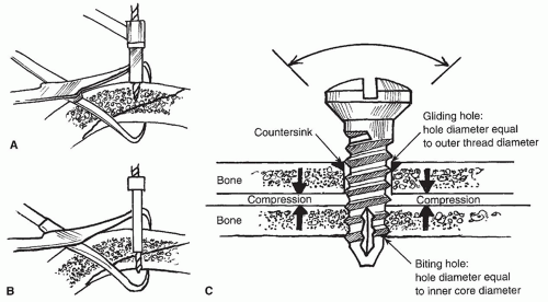 Figure 78.5 A: Drilling gliding hole for lag screw placement. The diameter matches the outer screw thread diameter. B: Drilling biting hole for lag screw placement. The drill bit diameter matches the inner core diameter of screw. C: Detail of lag screw. Diameter of bone hole closest to the head of the screw matches the outer diameter of the threads of the screw, allowing the screw to be pushed through or glide through the first hole without being turned. Diameter of the hole closest to the tip of the screw matches the inner core diameter of the screw. When the screw is tightened, the two pieces of bone are compressed together. |
TABLE 78.1 RECOMMENDED PLATE APPLICATIONS | |||||||||||||||||
|---|---|---|---|---|---|---|---|---|---|---|---|---|---|---|---|---|---|
|
INSTRUMENTATION
Application of plates and screws to bone requires specialized instrumentation. Typically, plating systems are self-contained in that they provide all the specialized instrumentation needed for application of the plates. Standard instrumentation for obtaining exposure of the fracture site, however, is not included. Scalpels, scissors, clamps, retractors, and periosteal elevators typically must be supplied in addition to the plating set.
The plating set itself has drill bits that are precisely matched to the screw size. As previously mentioned, a
hole that is too large will prevent the screw from engaging the bone. A hole that is too small may prevent adequate driving of the screw or, in the case of microsystems, cause shearing of the head off of the screw shaft as it is being driven. Typically, there is only one appropriate drill bit diameter for a given screw diameter, and it is usually the size of the screw shaft (i.e., the screw without its threads). An exception to this is found in some microplating systems where drill bits of two different diameters are appropriate for one particular screw diameter. The larger drill bit is used in areas where the bone is harder and thicker to reduce screw head shearing. A smaller bit is used where the bone is thinner or softer, particularly in pediatric cases, to increase screw thread hold. Drill bits with stop collars allow for drilling of a hole to a predetermined depth. The collar prevents overpenetration of the bit, protecting underlying structures.
hole that is too large will prevent the screw from engaging the bone. A hole that is too small may prevent adequate driving of the screw or, in the case of microsystems, cause shearing of the head off of the screw shaft as it is being driven. Typically, there is only one appropriate drill bit diameter for a given screw diameter, and it is usually the size of the screw shaft (i.e., the screw without its threads). An exception to this is found in some microplating systems where drill bits of two different diameters are appropriate for one particular screw diameter. The larger drill bit is used in areas where the bone is harder and thicker to reduce screw head shearing. A smaller bit is used where the bone is thinner or softer, particularly in pediatric cases, to increase screw thread hold. Drill bits with stop collars allow for drilling of a hole to a predetermined depth. The collar prevents overpenetration of the bit, protecting underlying structures.
Drill guides serve several purposes. They protect the surrounding soft tissue from injury by the rotating drill bit and allow for percutaneous drilling. The guide also serves to stabilize the rotating bit, allowing a more precise drill hole. Additionally, guides provide for more precise placement of a drill hole relative to a plate hole. Concentric drill guides place the drill hole in the center of the plate hole. Eccentric guides place the drill hole off center, allowing for compression as the screw head seats in the center of the plate hole. An addition is a guide with a curved extension that points to the drill bit exit site for through-and-through drilling. This extension allows more predictable drilling.
Stay updated, free articles. Join our Telegram channel

Full access? Get Clinical Tree


