Principles and Basic Techniques of Ocular Microsurgery
Marian S. Macsai
The outcome of ocular microsurgery depends on various factors, which include the surgeon’s technical skill, experience, knowledge of the basic techniques, and surgical judgment, as well as appropriate anesthesia, equipment, and instrumentation. This chapter introduces the beginning surgeon to the principles and basic techniques that are necessary to perform ocular microsurgery.
Microsurgery is distinctly different from general surgery.1 The operating microscope forces the surgeon to assume a particular posture that often must be maintained for several hours; this immobility sometimes hinders certain manipulations. The surgeon must understand this immobility and learn to work around it. The visual field is restricted, as is the space available for manipulation between the microscope and the operative field. The surgeon must become familiar with this spatial limitation and learn to manipulate instruments while visualizing them only through objectives of the operating microscope. Mastering the principles and basic techniques of ocular microsurgery is essential. The resulting surgical precision is elegant in both its technical and visual components.
Surgical Setup
Microscope Positioning
The operating microscope consists of the following elements: oculars, beam splitter, magnification system, and objectives (Fig. 3-1). The microscope may be mounted on the ceiling or on a mobile floor stand. Familiarity with the microscope is essential. To thoroughly understand the alignment of the movable parts of the microscope, the surgeon must take the time to disassemble and reassemble the apparatus. In addition, the beginning surgeon must become familiar with every rheostat and bulb on the operating microscope to compensate if an unexplained change in the illumination occurs during the surgical procedure. Both focus and magnification should be adjustable with a remote foot control (Fig. 3-2). The optical axis of the microscope on the operating field is adjusted with a foot pedal. The surgeon must ensure that the X-Y-Z centering buttons on the microscope have been reset before the start of any case. When the same operating theater is used repeatedly, a ceiling-mounted microscope requires little preparation on the part of the operator and permits rapid change of patients between operations under antiseptic conditions. It is beyond the scope of this chapter to describe the various types of microscopes available; however, surgeons selecting an operating microscope should be familiar with the major principles of function.
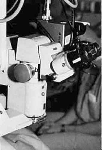 Fig. 3-1. The operating microscope has four essential elements: the oculars (A), the beam splitter (B), the magnification system (C), and the objective (D). |
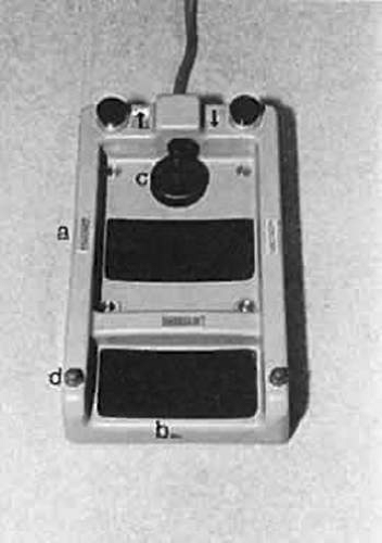 Fig. 3-2. View of the remote foot control. The focus (A), magnification (B), and optic axis of the microscope (C) may be adjusted. The joy stick is used to adjust the optic axis of the microscope. The operating microscope lights and room lights also may be adjusted by use of the foot pedal (D). |
Surgeon’s Positioning And Posture
During an operation, the surgeon should sit in a natural position, leaning slightly forward, with a straight back and relaxed shoulders. Both feet should be flat on the floor (Fig. 3-3). The surgeon must be well balanced on the stool, which should be locked to avoid surprise movement. The surgeon must be able to comfortably move both arms to manipulate the surgical instruments and both legs to operate the foot pedals without losing his or her balance or leaning on the patient or bed. This posture and the surgeon’s physique determine the optimal viewing direction in which the eyepieces should be inclined. Swivel-mounted oculars permit appropriate adjustments. In principle, it is possible to align the microscope obliquely on the operating field. This positioning may be required in special situations; in practice, a vertical alignment is customary. However, the oculars may be set at an oblique position to increase the surgeon’s comfort. The inclinable binocular tube can be adjusted for the most comfortable direction of gaze (Fig. 3-4). If properly aligned, the entire surgical field can be surveyed simply by dropping one’s gaze to the operative field.
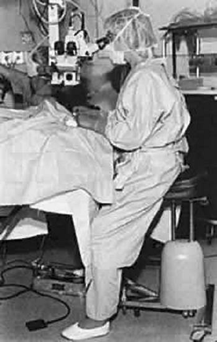 Fig. 3-3. Ideally, during ocular microsurgery, the surgeon should sit in a natural position with a straight back, leaning slightly forward. The shoulders should be relaxed. The oculars are set in an oblique position such that the angle of inclination provides comfortable alignment for the surgeon. |
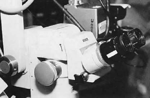 Fig. 3-4. The adjustable inclinable binocular tube (oculars) may be adjusted (arrow) for the most comfortable direction of gaze for the surgeon. In this manner, the entire surgical field is not in line with the surgeon’s gaze. |
The working distance, which is the distance from the oculars to the operating field, should lie within the reasonably comfortable range of 350 to 400 mm. This optimal distance can be exceeded with some types of microscopes if the beam splitter is interposed between the oculars and the body of the microscope. The actual space available for manipulation is determined by the distance between the objective lens and the operative field and should not be less than 150 mm.2
The operative field is rarely aligned with the direction of the surgeon’s gaze as he or she looks through the eyepieces (Fig. 3-5). This positioning should not impair eye-hand coordination. Movements of the surgeon’s instruments must be precisely controlled from the moment they appear within view under the microscope. In fact, within the modest range of magnification used in ophthalmic surgery, the surgeon’s control and manipulation are enhanced in direct proportion to the magnifying power selected.
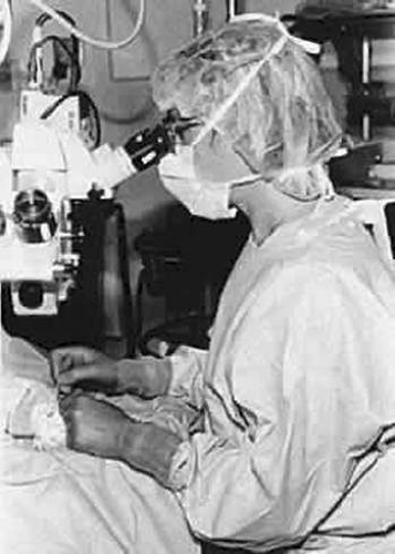 Fig. 3-5. The surgeon may view the entire operative field only by gazing down or looking around the microscope. As a result, the surgeon must develop eye-hand coordination to move the instruments within the surgical field viewed through the microscope. After the instruments have been visualized within the surgical field, they may be controlled precisely within the view under the microscope. |
The surgeon must be able to survey the entire surgical field beyond the microscope by dropping his or her gaze without retreating appreciably from the oculars. Inclinable ocular tubes are useful in this respect. The surgeon may elect to wear a spectacle correction to compensate for any refractive error or presbyopia. Surgeons who have a spherical refractive error may be more comfortable having their oculars adjusted to accommodate their spectacle correction. The primary ophthalmic surgeon may be seated at the head or side of the operating table, and the assistant ophthalmic surgeon seated to the side of the primary surgeon, leaving room for the scrub nurse (Fig. 3-6). The assistant should always be seated at a right angle to the surgeon. For example, when operating on the right eye from the superior position, the assistant sits to the surgeon’s right. However, if the primary surgeon is taking a temporal approach to the right eye, the assistant sits to the surgeon’s left, at the head of the table. With this positioning, instrument passing between the surgeon, the assistant, and the scrub nurse can be done with the greatest ease. However, instruments frequently need to cross the surgical field, and the assistant needs to avoid interrupting the passing of instruments.
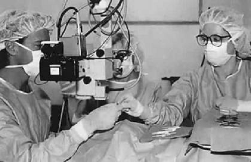 Fig. 3-6. The assistant should be seated at a right angle to the surgeon on the same side as the affected eye. For example, when operating on the left eye, the assistant sits to the surgeon’s left. The surgical scrub technician is positioned over the patient’s abdomen. Instruments frequently are passed across the surgical field to the operating surgeon. The assistant must make adjustments to avoid interrupting the passing of instruments from the surgeon to the scrub technician and possible resultant needle sticks. |
Before the surgical procedure begins, the microscope must be focused precisely. There is a tendency to focus down during intraocular procedures as the patient’s head settles in the headrest and as the eye softens. Therefore, the microscope should not be set in the middle of the range of focus; rather, it should be set two thirds of the way toward the top of the range of focus to allow for a greater range of downward focus during the procedure. The microscope should be raised until the field is out of focus and then lowered to the point at which the surgical plane is in focus. At this point, the assistant should adjust the oculars to focus on the same surgical plane. This maneuver prevents unnecessary accommodation during the surgical procedure. If the surgeon is considerably younger than the assistant, limiting accommodation is important. The microscope should be adjusted with a high power of magnification, taking advantage of the correspondingly narrowed depth of field to permit a more accurate focus. The magnification is subsequently reduced to a power appropriate for the procedure. This simple maneuver ensures a good depth of focus at normal working magnification, allowing for visualization of both the tips of the instruments and the suture or tissue.
Foot Pedal Positioning
A surgeon frequently must operate several foot pedals when performing microsurgery. In addition to the foot pedal for the operating microscope, other foot pedals may be required for phacoemulsification, mechanical vitrectomy, cautery, and lasers (Fig. 3-7). The surgeon must be comfortable and balanced on the operative stool so that both feet may be used to manipulate these pedals. For the shorter surgeon, it may be necessary to place the foot pedals on a platform. The surgeon should become familiar with using the pedal for the operating microscope on the same side for all procedures. Most surgeons prefer to control the microscope with their left foot and thus leave their right foot free to operate any ancillary pedals needed for cautery, irrigation-aspiration, or phacoemulsification. When using linear aspiration or phacoemulsification, precise control of the foot pedal is essential. Because many surgeons use their right foot to drive a car, they use the same right foot to operate these pedals. However, each surgeon will have an individual preference.
Hand Positioning and Support
To precisely manipulate microsurgical instruments, maximum precision is required. To achieve this precision and a steady hand, the surgeon’s hand may require support. Support can be provided in the middle of the forearm with an armrest that is attached to the operating stool, support may come from the other hand that is not holding the instrument, or it can be provided directly behind the wrists by a wrist rest that attaches to the operating table (Fig. 3-8). The wrist rest should be set to the height of the patient’s lateral canthus. Alternatively, the surgeon may rest his or her hands on the brow and cheek of the patient during the surgical procedure. Whatever the form of support, it should be used to support the hand and not to stabilize the surgeon while leaning forward. The surgeon should be well centered and stable on the stool with shoulders relaxed such that the arms rest gently on the support. When operating, the surgeon must have a light touch so that his or her hands are “floating” and the surgeon is not leaning into the field.
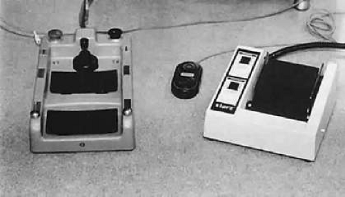 Fig. 3-7. Numerous foot pedals must be set up under the operating table. The surgeon must be able to operate these pedals without seeing them. The operating microscope remote control foot pedal is shown on the left, with an irrigation/aspiration, vitrectomy, and phacoemulsification control on the right. The small black pedal in the middle is used for cautery. |
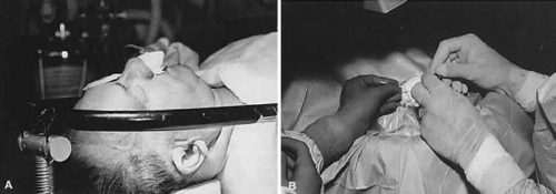 Fig. 3-8. A. A wrist rest can be set up to stabilize the surgeon’s hands. During the procedure, the height of the wrist rest should be set to the level of the patient’s lateral canthus. B. Depending on the size of the surgeon’s hand, a wrist rest may provide support for the wrist or the hand. |
Positioning the Patient for Ocular Microsurgery
The patient is frequently under conscious sedation when undergoing ocular microsurgery. As a result, the patient should be both comfortable and in a position that maximizes the surgeon’s approach. The patient is placed supine on the operating table. Ideally, a bed specifically designed for eye surgery should be used that allows the head to be positioned separately from the rest of the body. This style bed is ideal for accommodating patients who are obese, with upper back or neck deformities, or with limited mobility. When an eye bed is used, the patient can be positioned in the preop area and then brought into and out of the operating room on the same bed, avoiding unnecessary transfers. Ideally, the patient should be placed supine with the legs slightly bent, resting on a pillow under the thighs to relieve pressure on the lower back. The bed must be high enough for the surgeon to get his or her legs under the bed and operate the foot pedals, but the surgeon also must be able to see through the operating microscope oculars. The patient’s head should be resting in a headrest that is attached to the bed and can be positioned separately from the rest of the bed. A separate headrest allows the surgeon to sit closer to the head, avoiding reaching across the operating table to reach the eye. The head should be positioned so that the patient’s cornea is parallel with the floor when gazing at the ceiling. The eye should be centered between the lids. In the obese patient special attention must be paid to the positioning of the patient to avoid posterior vitreous pressure during the surgical procedure. The patient should be positioned in the standard manner, and then the bed should be placed in reverse Trendelenburg to lower the center of gravity of the patient’s torso to the level of the eye. (Fig. 3-9) In these patients a slight hyperextension of the neck may be required to bring the cornea to a centered position between the lids and parallel to the floor. It is very important to consider the patient’s center of gravity as it relates to the level of the eye and to keep the eye at or above this point.3 If the center of gravity of the eye is below the center of gravity of the torso, significant posterior vitreous pressure may occur and complicate the surgical procedure. (Fig. 3-10)
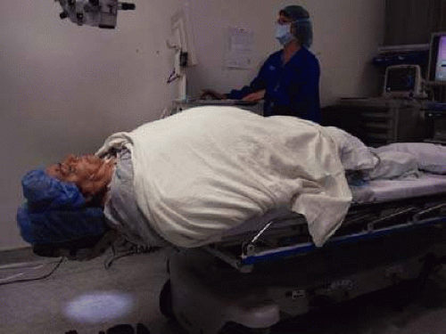 Fig. 3-9. Correct positioning of the obese patient. The head is placed in a headrest and the bed is placed in reverse Trendelenburg to lower the center of gravity of the patient’s torso to the level of the eye. In this position, the eye is equal to the center of gravity of the patient’s torso. The maneuver will decrease unnecessary posterior vitreous pressure during intraocular surgery. |
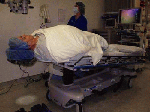 Fig. 3-10. The obese patient is incorrectly positioned for intraocular surgery. The head is in a dependent position, below the center of gravity of the patient’s torso. This positioning will result in increased posterior vitreous pressure during intraocular surgery. In addition, the patients’ airway is more compressed and increases the possibility of oxygen desaturation during the procedure. |
Preparing the eye for Ocular Microsurgery
The first step in ocular microsurgery is maintaining separation of the eyelids and preventing the patient from squeezing during the procedure. The eyelids must be opened enough to allow adequate visualization and manipulation of the intraocular instruments. Should the patient inadvertently attempt to blink during surgery, this should not result in increased intraocular pressure (IOP). Many different techniques can be used to separate and stabilize the eyelids, including traction sutures or lid specula. Traction sutures are effective in obtaining lid separation and retraction (Fig. 3-11) and are most effective when passed through the tarsus; however, there is a tendency for the lids to evert. A lid speculum may be self-retaining or of the spring-tension variety (Fig. 3-12). Each speculum offers certain advantages. Some specula, which offer the additional option of aspiration, can be attached to suction devices to keep the fornices dry during the procedure. The spring-tension wire or solid-blade speculum opens the lids to the extent of the spring tension. However, spring tension is not adjustable, and the speculum may rotate intraoperatively. Many lid speculum designs are available with a screw clamp design. A lid speculum with a screw clamp device, such as the Schott lid speculum, allows the lids to be separated and retracted off the globe when the lid hooks are everted individually.4 This lid speculum provides an excellent surgical field without resulting in increased IOP. This feature is especially important if the surgeon or assistant inadvertently leans on the lid speculum during the operation. With the Jaffe lid speculum, the upper and lower lid hooks are individually secured to the head drape. This type of speculum offers some advantage when operating on patients with a prominent brow or deep-set orbits. The wire speculum may be formed to the patient’s brow to allow for better retraction of the upper lid. With any of these techniques, it is theoretically possible to disinsert the levator muscle from the superior aspect of the tarsus, resulting in postoperative ptosis. Therefore, overretraction of the lids must be avoided.
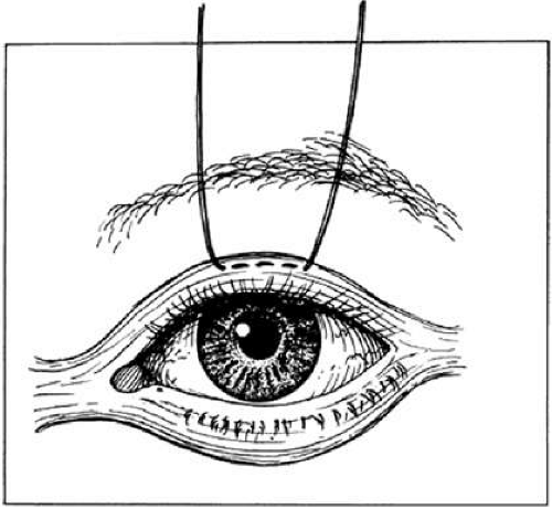 Fig. 3-11. A traction suture is placed through the skin and tarsus to provide traction on the lid. However, there is a tendency for the lids to evert during the procedure. |
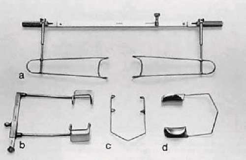 Fig. 3-12. Various types of lid specula are available. One is the Schott lid speculum (A). An alternative is a screw-clamp speculum (B). A spring-tension wire speculum (C) or a solid blade speculum (D) opens the lids to the extent of the spring tension. |
Microsurgical Instrument Technique
Holding Instruments
Microsurgery requires fine control of instruments. To achieve this control, the surgeon must be familiar with the advantages of different instrument designs. Some surgical instruments have a serrated flat handle, others have a round knurled handle, and still others have a round serrated handle (Fig. 3-13). The serrated or knurled areas allow the surgeon a firmer grasp and better control of the surgical instrument. An instrument with a round, knurled handle may be rotated in the fingertips, allowing greater flexibility during some procedures. For example, some types of tying forceps are designed with this option. In contrast, most ocular scissors have a flat serrated handle.
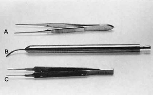 Fig. 3-13. Three surgical instruments with three handle styles. A. A flat serrated handle. B. A round serrated handle. C. A round knurled handle. |
Holding surgical instruments correctly provides the surgeon increased flexibility and mobility. The serrations on the handle, regardless of style, allow the surgeon to hold the instrument lightly but firmly. With the level of precision of currently available instruments, it is never necessary to grasp an instrument tightly. The tendency to grasp instruments tightly must be avoided because it decreases flexibility and increases fatigue of the hand and forearm muscles. Any resistance encountered when placing an instrument into or out of the eye is secondary to positioning of the instrument. Adjusting the angle of the instrument or your hands should allow easier placement of the instrument.
No surgical instruments are intended to be held like a pencil, resting in the crotch between the thumb and forefinger (Fig. 3-14).5 In conventional eye surgery, longer instruments usually are rested against the first metacarpophalangeal joint, with the thumb and first two fingers encircling the handle. Stability is achieved by resting the side of the fifth finger on the periorbital facial structures. This method of holding surgical instruments allows rotation of the instrument between the fingertips, by flexing the fingers, or by rotating the wrist. Great mobility is necessary when using a needle holder (needle driver) to pass a needle through tissue. When the surgeon encounters resistance from the tissue, it is usually necessary for the surgeon to twist the wrist or apply counter pressure on the tissue at the exit site of the needle.
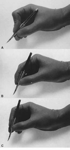 Fig. 3-14. A. A surgical instrument held like a pencil, resting in the crotch between the thumb and the forefinger. No surgical instruments are intended to be held in this manner. B. A longer surgical instrument held resting against the first metacarpophalangeal joint of the first finger, with the thumb and the first finger encircling the handle. This position allows for rotation of the instrument between the fingertips or by flexing the fingers or wrist. C. The surgical instrument is held between the thumb and fingertips of the second and third digits. This position allows for a more perpendicular positioning of the instrument on the eye. |
Instruments are designed to be held on the serrated portion of the handle. Holding them more anterior or posterior alters the force applied and may result in malfunctioning of the instrument. Frequently, the beginning surgeon complains that an instrument does not hold a fine suture, such as 10-0 nylon. Often, this problem results from improper handling of the instrument. For example, the design of a surgical tie calls for the surgeon to apply pressure at the flat serrated handle to ensure that the tying platforms meet properly. If a torque or oblique force is applied to the tying forceps, the 10-0 nylon may be inadvertently sheared or may not be grasped tightly. To avoid this problem, various instruments have a guide incorporated into the handle. The guide requires proper alignment for the instrument to close (Fig. 3-15). The same difficulty may be encountered when using a locking needle holder. The lock will hold only if the needle holder is positioned properly within the surgeon’s fingertips and the force applied is not oblique to the handle. If the forces applied to the instruments exceed those designed in its construction, the components of the instrument will bend and the jaws will not appose correctly (Fig. 3-16).6
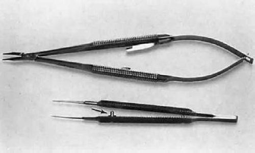 Fig. 3-15. A surgical tie is shown on the bottom. A guide is incorporated into the handle (arrow). The guide ensures proper alignment for the instrument to close. On the top, a locking needle holder is shown. The lock will hold only if the needle holder is positioned properly in the surgeon’s fingertips and the force applied is not oblique to the handle. |
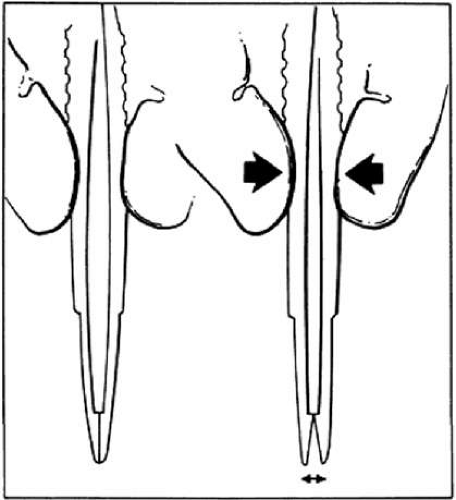 Fig. 3-16. When a proper degree of force is applied to the instrument, the tips will align properly. However, if greater forces are applied, the instrument bends and the jaws do not appose correctly. |
Grasping Tissue
Before using a forceps to grasp tissue, the surgeon must have a clear understanding of how the instrument holds tissue and the extent of damage caused by the instrument. In ophthalmology, three instruments are used to grasp tissue: smooth forceps, toothed forceps, and a spatula (or hook).
Smooth forceps (i.e., forceps without teeth) must be used when handling delicate tissues (Fig. 3-17). For example, smooth forceps are necessary when working with tissue that must not be punctured or damaged, such as the conjunctiva during a trabeculectomy. An absolutely smooth forceps with no defined grasping surface usually is ineffective when handling the conjunctiva. A tying forceps (a smooth forceps) is used to hold fine suture. A serrated platform has undulations or serrations that grasp the tissue surface and provide increased friction without damaging the tissue. It is effective in handling the conjunctiva because the conjunctival surface can conform to the ridges of the serration. Criss-cross serrations permit traction in all directions. An alternative is the Pierse-type forceps, which has no teeth but has a small hollow area immediately posterior to the smooth tip. This hollow area allows for tissue displacement instead of the tearing of tissue that occurs with sharp-toothed forceps. If one attempts to use a serrated forceps on rigid material, such as the sclera, only the tips of the serrated platform will hold the tissue, reducing the contact area and effectiveness of the forceps (Fig. 3-18). Therefore, toothed forceps must be used to grasp the sclera effectively.
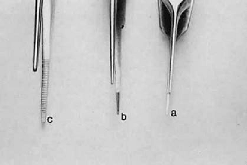 Fig. 3-17. Three different smooth forceps. On the right is an absolutely smooth forceps (A). In the middle is a grooved forceps (B). On the left is an instrument with a serrated platform (C). The instrument on the right is used to grasp fine suture, whereas the instrument on the left is more commonly used to handle conjunctiva or thin tissue that can conform to the ridges of the serration. |
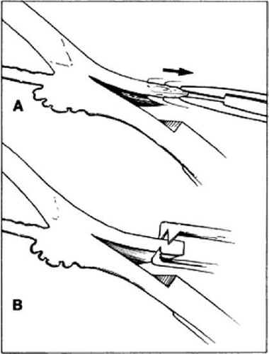 Fig. 3-18. When a smooth forceps is used to grasp rigid material, only the tips of the instrument hold the tissue, thus reducing the contact area and effectiveness of the forceps. A. When a smooth forceps is used to grasp rigid sclera, the forceps slips. B. Toothed forceps may be used more effectively to grasp rigid tissue such as the sclera or cornea. |
A toothed forceps is needed for firm or tough tissue, such as the cornea or sclera, whereas soft tissues, such as the iris or conjunctiva, are better handled with a smooth forceps (Fig. 18). Surgical toothed forceps can damage delicate tissue; however, these forceps exert a high degree of resistance, which is necessary for manipulating tougher tissues. Toothed forceps can have teeth at a 90° angle (surgical forceps) or angled teeth (mouse-tooth forceps; Fig. 3-19). An example of a surgical toothed forceps is a 0.12-mm forceps; an example of a forceps with angled teeth is the O’Brien forceps. Microscopic examination of the instrument from the side determines tooth design. Forceps with angled teeth can seize tissue lying in front of the forceps. For example, these forceps can be used to grasp the muscle insertion through the conjunctiva (Fig. 3-20). The toothed forceps grasp a minimal amount of tissue and produce minimal surface deformation, frequently without penetrating the tissue. The angle-tooth forceps can be useful for grasping the cornea during corneal transplant surgery or repair of corneal lacerations. If the teeth are dull or bent, the forceps are ineffective. The number and orientation of the teeth on a forceps affect the stability of fixation and tissue damage. Teeth angled at 90° provide good fixation but greater tissue damage than teeth angled at 45° (mouse-tooth forceps). Increasing the number of teeth also increases the degree of tissue fixation. One example is the Thorpe corneal fixation forceps, in which teeth are in a 2 × 3 configuration. The Thorpe corneal fixation forceps has 45° angled 0.12-mm teeth in a 2 × 3 configuration, thus allowing for increased stability of tissue fixation, with limited tissue damage. When driving or passing a needle through tissue that is fixed with a toothed forceps, the forceps should be held such that the needle enters the tissue on the side of the forceps with the greatest number of teeth. In other words, when a Thorpe corneal fixation forceps is used, the needle should pass through the tissue on the edge that is secured by three teeth, and when using a 0.12 forceps, the needle should pass through the tissue on the edge with two teeth. This maneuver limits the twisting of the tissue as the needle is advanced through the tissue.
Stay updated, free articles. Join our Telegram channel

Full access? Get Clinical Tree


