Plain Roentgenographic Evaluation of Orbital Disease
Keith D. Carter
Gina Rogers
Jeffrey A. Nerad
Assessment of a patient with suspected orbital disease or trauma should begin with clinical evaluation, but the interior of the orbit, unlike the eye, cannot be observed directly. This limitation often necessitates radiologic studies as an adjunct to aid in diagnosis.
Until the 1980s, conventional radiography and linear tomography were the primary diagnostic methods used for imaging the facial skeleton. The development of high-resolution computed tomography (CT) and magnetic resonance imaging (MRI) have largely replaced conventional radiography as the primary imaging modalities to assess orbital disease. These newer techniques provide better resolution and details of both bone and soft tissues. Despite the widespread availability of CT and MRI, conventional radiography many be an initial or only available modality in some scenarios. Plain x-ray films can delineate bony detail of the orbit and face, along with moderate soft tissue changes. The incidence of definitive positive findings with plain film evaluation of orbit diseases ranges from 10% to 42%.1,2,3,4 This chapter demonstrates the techniques and utility of plain films in evaluating orbital pathology.
Radiologic Principles
Because the orbit is in such close proximity to the larger bones of the skull, multiple shadows overlap one another and obscure some radiographic details. Numerous radiologic projections have been developed to evaluate the bony structures of the orbit and face.5,6 These various projections attempt to eliminate some of the overlapping shadows and allow for better detail of the bony orbit. For maximal image clarity, the distance from the object to the x-ray cassette should be minimized and the distance between the subject and the x-ray beam maximized. This principle is demonstrated in Figure 23-1.
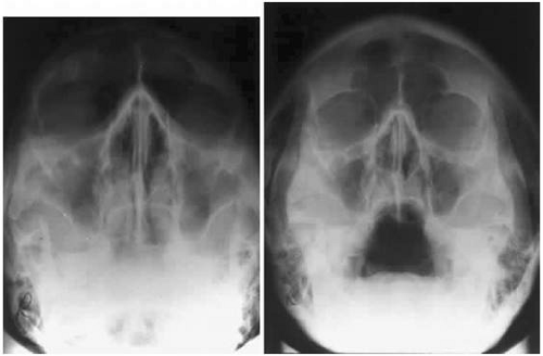 Fig. 23-1. In any projection image, detail is maximized using the minimal distance from the subject and the x-ray cassette. A. Anterior to posterior projection demonstrating decreased clarity and definition of anterior structures. B. Posterior to anterior projection showing the improved clarity of the anterior structures, such as the orbital rim and frontal sinus. |
Standard Orbital Views
A standard radiographic study of the orbit and paranasal sinuses consists of the following four views: Waters (occipitomental projection), Caldwell (occipitofrontal projection), lateral projection, and basal projection (submentovertex) views. Oblique apical projections of the optic canals are additional views that are available if there is concern of posterior orbital pathology, such as traumatic optic neuropathy or an optic nerve tumor.
Waters Projection
In an attempt to improve the visualization of the maxillary and ethmoid sinuses, in 1915 Waters and Waldron7 described a radiographic projection (Fig. 23-2) that eliminated the overlapping shadows of the dense petrous ridge of the temporal bone. Waters projection is created by placing the chin of the patient on the x-ray cassette with the canthomeatal line (the line that connects the lateral canthus and the external auditory meatus) at 37° to 45°.5,6 This orientation is accomplished if the nose of the patient is approximately 0.5 to 1.5 cm above the x-ray plate.7,8 A mnemonic to remember this orientation is—the patient raises the chin up to sip water.
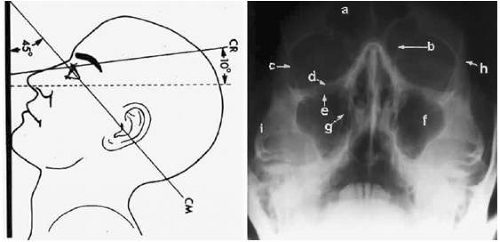 Fig. 23-2. A. Schematic showing positioning for a Waters projection. (CM, canthomeatal line; CR, central ray.) B. Radiograph of a Waters projection. The petrous ridge lies below the maxillary sinus. (a, frontal sinus; b, medial orbital wall; c, innominate line; d, inferior orbital rim; e, orbital floor; f, maxillary antrum; g, superior orbital fissure; h, zygomatic frontal suture; i, zygomatic arch.) (A:;eproduced with permission from Rao VM, Gonzalez CF: Plain film radiography and polytomography of the orbit. In Gonzalez CF, Becker MH, Flanagan JC (eds): Diagnostic Imaging in Ophthalmology. New York: Springer-Verlag, 1986:1–7.) |
The Waters view provides the best image of the maxillary antrum and good images of the orbital rim, orbital floor, zygomatic bones and arches, lesser wing of the sphenoid, and infraorbital foramen. This view is useful to the clinician in orbital floor fracture assessment because of the clear image of the orbital floor and the underlying maxillary sinus. The floor of the orbit should form a continuous radiographic line with the lateral wall of the orbit. Confusion can occur regarding the location of the orbital floor and its relationship to the orbital rim. The orbital floor is located inferior to the orbital rim, not in the same plane, because of the orientation of the patient’s head in a Waters projection. A soft tissue density in the roof of the maxillary sinus or opacification of the floor of the sinus suggests an orbital floor disruption.
Caldwell Projection
In 1918, Caldwell9 described a projection (Fig. 23-3) that minimized the superimposition of the sphenoid bone on the paranasal sinuses. The patient is positioned with both the nose and forehead against the x-ray cassette while the x-ray beam is directed downward 15° to 23° to the canthomeatal line.5,6,9 This orientation also projects the petrous bones inferior to the orbit, thus avoiding obscuration of the orbital structures. As in the Waters view, the Caldwell view is a posterior-anterior projection. This excellent view of the frontal and ethmoid sinuses also allows good visualization of the orbital rims, greater and lesser sphenoid wings, lacrimal gland fossa, medial orbital wall, and both the superior and inferior orbital fissures.10 The innominate line is prominent in this view and represents the depression on the temporal surface of the greater wing of the sphenoid bone where it forms the medial wall of the temporal fossa or lateral wall of the orbit. This innominate line can be straight, end with a medial right angle turn, or continue inferiorly to form the outline of the pterygoid plate.8 A lack of continuity of the innominate line suggests a fracture of the lateral orbital wall.
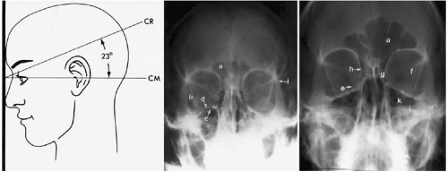 Fig. 23-3. A. Schematic showing positioning for a Caldwell projection. (CM, canthomeatal line; CR, central ray.) B. Radiograph of a Caldwell projection. The petrous ridge is positioned at the orbital floor. Detail of the orbital floor and maxillary sinus is blocked. C. The radiograph is taken at a steeper angle so the petrous ridge is now positioned lower within the maxillary antrum. (a, frontal sinus; b, innominate line; c, inferior orbital rim; d, posterior orbital floor; e, superior orbital fissure; f, greater wing of sphenoid; g, ethmoid sinus; h, medial orbital wall; i, petrous ridge; j, zygomatic frontal suture; k, foramen rotundum.) (A:;eproduced with permission from Rao VM, Gonzalez CF: Plain film radiography and polytomography of the orbit. In Gonzalez CF, Becker MH, Flanagan JC (eds): Diagnostic Imaging in Ophthalmology. New York: Springer-Verlag, 1986:1–7.) |
Lateral Projection
The lateral projection (Fig. 23-4) is created by placing the patient’s head against the x-ray cassette and centering the cassette on the lateral canthus. The x-ray beam is directed perpendicularly to the midpoint of the cassette and enters the patient’s head at the lateral canthus remote from the cassette.5,6 This projection provides a view of the sagittal plane of the skull. Because of the overlapping skeletal structures, interpretation of unilateral disease processes is difficult. The structures that can be identified and best evaluated with this view include the sphenoid, frontal, ethmoid, and maxillary sinuses. This lateral view also shows the sella turcica, the anterior and posterior clinoid processes, the nasopharynx, and the cribriform plate. The orbital structure best evaluated is the orbital roof. The floor of the orbit is visible, but evaluation is difficult because of the upward slope, from lateral to medial, toward the orbital apex. This slope causes the floor to appear at different levels on the lateral view.11 The lateral projection, although not as useful as the frontal projections, gives information concerning air–fluid levels in traumatized patients, when only a horizontal projection is possible and detecting fractures which extend through the pterygoid plate as occurs with the LeFort fractures.
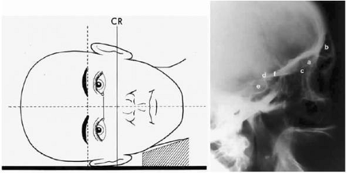 Fig. 23-4. A. Schematic showing positioning for a lateral projection. (CR, central ray.) B. Radiograph of a lateral projection. (a, orbital roof; b, frontal sinus; c, ethmoid sinus; d, anterior clinoid process; e, sella turcica; f, planum sphenoidale.) (A; Reproduced with permission from Rao VM, Gonzalez CF: Plain film radiography and polytomography of the orbit. In Gonzalez CF, Becker MH, Flanagan JC (eds): Diagnostic Imaging in Ophthalmology. New York: Springer-Verlag, 1986:1–7.) |
Basal Projection (Submentovertex)
The basal projection (Fig. 23-5) for the evaluation of the sphenoid sinus, zygomatic arch, and skull base was described initially by Arthur Schuller12 in 1905 and later popularized in this country by Bowen.13 This projection is obtained with the patient’s neck extended either in the supine or upright position. The top of the head is placed so that the infraorbitomeatal line is parallel with the x-ray cassette. The x-ray beam is directed at right angles to the infraorbitomeatal line.5,6 This view shows the lateral walls of the orbit and maxillary sinuses well. The nasopharynx, pterygoid plates, pterygopalatine fossa, and the sphenoid and ethmoid sinuses may also be inspected. Because of the extreme head position, any history of a neck injury is a contraindication to this radiologic study.
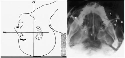 Fig. 23-5. A. Schematic showing positioning for a basal projection. (CR, central ray; IM, infraorbitomeatal line.) B. Radiograph of a basal projection. (a, zygomatic arch; b, orbit; c, lateral orbital wall; d, posterior wall of maxillary sinus; e, pterygoid plate; f, sphenoid sinus.) (A:;eproduced with permission from Rao VM, Gonzalez CF: Plain film radiography and polytomography of the orbit. In Gonzalez CF, Becker MH, Flanagan JC (eds): Diagnostic Imaging in Ophthalmology. New York: Springer-Verlag, 1986:1–7.) |
Optic Foramen (Rhese Position)
In 1911 Rhese14 described a projection (Fig. 23-6) for the evaluation of the ethmoid sinuses and the optic foramen. The patient is positioned with the orbit to be studied against the x-ray cassette. The zygoma, nose, and chin should touch the cassette. The x-ray beam is directed posterior-anteriorly at 40° to the midsagittal plane.5,6 In this position the optic canal is in the inferolateral quadrant of the orbit and oriented perpendicular to the x-ray cassette.15 Variations of this standard position can be used to view other structures of interest. The Rhese projection allows assessment of the orbital apex, in particular, the optic foramen, optic strut, and the upper ethmoid sinus. A pneumatized anterior clinoid process may simulate the optic foramen. The landmark for finding the foramen is to find the planum sphenoidale; the optic foramen lies at its lateral end. The optic canal may be evaluated for expansion or compression by disease processes, such as optic nerve tumors (glioma and meningioma) and trauma. CT and MRI images show much better detail and therefore have replaced the use of plain films for evaluation of the optic canal.
Stay updated, free articles. Join our Telegram channel

Full access? Get Clinical Tree


