graduated from Chiba University in 1975 and received his doctoral degree from Tokyo Institute of Technology (T.I.T.) in 1981. He joined Toppan Printing Company in 1982 and the faculty of engineering of Chiba University in 1990. Dr. Ohnuma is currently an associate professor of medical engineering at Chiba University in Chiba.

graduated from Hamamatsu University School of Medicine in 1986. Dr. Noda had been a part-time professor of Tokyo Women’s University School of Medicine from 1991 to 2012 and is currently a chief in the Department of Ophthalmology at National Hospital Organization Tokyo Medical Center and also a clinical professor of graduate school of nursing studies at Tokyo Healthcare University.

is Director and Professor of Ophthalmology at Tokyo Dental College Suidobashi Hospital, Tokyo, Japan, where she specializes in cataract and refractive surgery. She holds both Japanese and German doctoral degrees. She is on editorial board of several medical journals. She is the current president of JSCRS and past president of International Intraocular Implant Club.

15.1 Introduction
Premium intraocular lenses (IOLs) have the advantage to improve quality of vision compared to the conventional single-focus (monofocal) IOLs. The premium IOLs consist of multifocal IOL, toric IOL, accommodative IOL, and a combination of them. The multifocal IOLs create multiple focal points so patients are able to see well at varied distances and accommodative IOLs are engineered to mimic the eye’s natural process of accommodation, while the monofocal IOLs provide either distance or near vision.
Refractive and diffractive multifocal IOLs enable the patients to achieve favorable far and near vision without corrections [1, 2]. A decrease of sensitivity and/or haloes at nighttime has been reported. With the increase in the number of eyes implanted with multifocal IOLs, the possibility of having to perform vitreoretinal surgery in these eyes must be considered. Some surgeons concluded that the surgery was difficult because of the design of the optics of the multifocal lenses [3–5] while others reported no difficulties [6, 7].
Toric IOLs can compensate symmetrical corneal astigmatism to improve better naked vision [8–10]. This has led to an increase in the number of eyes implanted with toric IOLs which increases the probability that vitreoretinal surgery will have to be performed on some of these eyes. Cylindrical aberrations caused by toric IOLs could distort the image of the retina or could reduce stereopsis during the surgery. A computer-calculated simulation of the images viewed through toric IOLs has been reported, and the meridional aniseikonia that occurs after implantations of toric IOLs for correction of high corneal astigmatism has been investigated [11].
We believe that knowledge of the retinal images observed during vitreous surgery through the different types of multifocal and toric IOLs is important. A comparison of the images viewed through different multifocal IOLs has been reported in a model eye system [12]. To study an eye that was more comparable to the human eye, we constructed a model eye whose corneal lens had the average value of spherical aberration of human eyes. The aim of this study was to compare the quality of a grating target placed in the model eye and viewed through refractive and diffractive multifocal IOLs and toric IOLs.
15.2 Methods
15.2.1 Retinal Imaged Through the Multifocal IOL
Refractive (NXG1, ReZoom®, Abbott Medical Optics, or PY60MV, iSii®, HOYA Corp.) or diffractive (ZM900, Tecnis® Multifocal, Abbott Medical Optics, or SA60D3, ReSTOR®, Alcon Laboratories) multifocal IOLs were placed in a fluid-filled model eye with human corneal aberrations of +0.22 μm (Fig. 15.1). A US Air Force resolution target was placed on the posterior surface of the model eye as targets of retinal images. A flat contact lens or a wide-field contact lens was placed on the cornea. The images of gating targets were observed through the operating microscope and the central images were focused. Then, the images were photographed and the contrasts of the gratings were evaluated under endoillumination supplied by vitrectomy machine and compared to those obtained through a monofocal spherical IOL (SA60AT, Alcon Laboratories). All IOLs have the same spherical power of +20.0 diopters.
Fig. 15.1
Cross-sectional drawing of the model eye. (a) Schematic drawing of the model eye based on the Gullstrand model eye. (b) The US Air Force (USAF) grating target is glued to the posterior surface of the model eye. Modified and reprinted with permission from Elsevier Limited from Inoue et al. [19]
15.2.2 Retinal Imaged Through the Toric IOL
Toric IOLs with a cylinder power of 3.0 diopters (SN6AT5, Alcon Laboratories, or 311 T5, HOYA Corp.) and with that of 6.0 diopters (ST6AT9, Alcon Laboratories, or 311 T9, HOYA Corp.) were placed in the fluid-filled model eye with human corneal aberrations. A US Air Force test target was placed internally on the posterior surface of the model eye and a flat contact lens or a wide-angle contact lens was placed on the cornea in a similar way of the experiment of multifocal IOLs. The contrast and length of the grating targets perpendicular (vertical) or parallel (horizontal) to the flat meridian axis of the toric IOL were compared to those obtained through aspheric IOLs (SN60WF, Alcon Laboratories, or NY-60, HOYA Corp., Fig. 15.2).
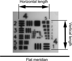
Fig. 15.2
The horizontal and vertical lengths of the central target. The toric marks of the flat meridian axis of the toric IOL are positioned at the horizontal marks of the model eye. The horizontal and vertical lengths of the central target against the flat meridian axis are measured. Reprinted with permission from Elsevier Limited from Inoue et al. [20]
15.2.3 Astigmatism Aberration of Toric IOL Measured with Wavefront Analyzer
The toric and aspheric IOLs were implanted in the model eye and the flat meridian axis was set at 0°. A wavefront analyzer (KR-1 W, Topcon Medical System Inc., Tokyo, Japan) was used to measure the cylindrical aberration of the IOLs for an image of 5 mm because the diameter of the optics of all the IOLs was 6.0 mm and the valid optics of the toric IOLs was at least 5 mm. The internal aberrations that represented the aberrations of the IOLs were measured with the wavefront analyzer. In the device, the internal aberration was calculated to subtract the corneal aberration of the model eye from the aberration of the whole eye.
15.3 Results
15.3.1 Retinal Imaged Through the Multifocal IOL
The grating images were clear when viewed through flat and prism contact lens and through the central far-vision zone of the NXG1 and PY60MV although those through the near-vision zone were blurred and doubled (Fig. 15.3). The images observed through the central area of the ZM900 with flat and prism contact lens were slightly defocused, but the images in the periphery were very blurred. The contrast decreased significantly in low frequencies (P < 0.001, Fig. 15.4). The images observed through the central diffractive zone of the SA60D3 were slightly blurred, although the images in the periphery were clearer than that of the ZM900. The images were less blurred in all of the refractive and diffractive IOLs with the wide-field contact lens.
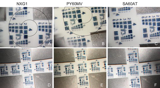
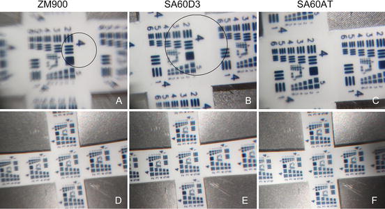
Fig. 15.3
Image of grating target in model eye implanted with refractive multifocal intraocular lens. (a) The central area (within the inner circle) is focused through NXG1 with flat contact lens although the refraction-added zone (within the outer circle) for near vision is blurred and doubled. (b) The refraction-added zone (between the inner and outer circle) is defocused and doubled through PY60MV with flat contact lens compared to (c) monofocal SA60AT. (d–f) No defocused image is observed through a wide-angle viewing lens in NXG1, PY60MV, and SA60AT. Reprinted with permission from Elsevier Limited from Inoue et al. [19]
Fig. 15.4


Image of grating of model eye implanted with diffractive multifocal intraocular lens. (a) The central area (within the circle) is focused with ZM900 through a flat contact lens although the peripheral images (out of the circle) are doubled. The ghost images are arranged in a centrifugal direction of the original image. (b) The central area (within the inner circle) is focused with SA60D3 but with lower contrast than that (c) with the SA60AT. (d) Images are not blurred when grating is observed through the wide-angle viewing lens in ZM900, (e) SA60D3, and (f) SA60AT although image of the SA60D3 is more focused. Reprinted with permission from Elsevier Limited from Inoue et al. [19]
Stay updated, free articles. Join our Telegram channel
Full access? Get Clinical Tree
