I
iatrogenic Relating to a disorder induced by the treatment itself. Example: the development of amblyopia in the good eye following occlusion treatment.
idiopathic Relating to any primary pathological condition of unknown origin.
idoxuridine See antiviral agents.
illiterate chart See chart, illiterate.
illuminance Quotient of the luminous flux, F, incident on an element of surface divided by the area, A, of that element of surface. Symbol: E. Thus

The units are in lux or footcandles. Syn. illumination.
See law of illumination, inverse square; photometer.
illuminance, retinal See retinal illuminance.
illuminants, CIE standard The colorimetric illuminants A, B, C and D defined by the CIE in terms of relative spectral energy (power distribution): standard illuminant A representing the full radiator at T = 2854 K; standard illuminant B representing direct sunlight with a correlated colour temperature of T = 4874 K; standard illuminant C representing daylight with a correlated colour temperature of T = 6774 K; standard illuminant D representing daylight with a correlated colour temperature of T = 6504 K (CIE).
See chromaticity diagram; lamp, Macbeth; light, white.
illumination 1. The action of brightening an object with light. 2. The science of the application of lighting. 3. Synonym for illuminance.
diffuse i. In slit-lamp examination, it is the illumination obtained with a wide slit and an out of focus beam or with a diffuser, thus providing an overall view of the structures of the eye.
direct i. In slit-lamp examination, the slit beam and the microscope are both focused sharply on the structure to be observed. Syn. focal illumination.
focal i. See illumination, direct.
indirect i. In slit-lamp examination, the slit beam is focused on a structure located adjacent to the structure to be observed.
inverse square law of i. See law of illumination, inverse square.
oscillation i. In slit-lamp examination, it is a technique in which the beam of light is oscillated to provide alternative direct and indirect illumination. It sometimes allows one to see slight changes more easily which otherwise would remain unnoticed under sustained illumination of either kind.
retinal i. See retinal illuminance.
retro-i. In slit-lamp examination, it is a method of illuminating a structure by using the light that is reflected by the iris or an opaque or senescent lens. This method is closely related to indirect illumination and often in corneal examination part of the cornea will simultaneously be under retro- and indirect illumination. Syn. transillumination.
See clouding, central corneal; oedema.
sclerotic scatter i. In slit-lamp examination, it is a method in which the beam of light is focused on the sclera near the limbus and the cornea remains uniformly dark in the absence of an opacity. However, an opacity in the cornea becomes easily visible as it scatters light.
See clouding, central corneal; oedema.
specular reflection i. In slit-lamp examination, it is a method in which the beam of light and the microscope are placed at equal angles from the normal to the corneal or lens surface to be viewed. This is a method for examining the quality of a surface. This method is particularly useful to observe the corneal endothelium.
See blebs, endothelial; cornea guttata; shagreen.
illuminometer See photometer.
illusion A false interpretation of an object or figure presented to the eye (visual illusion). Illusions can occur with each of the senses. See figure, ambiguous.
autokinetic visual i. The apparent motion of a luminous object fixated in the dark, or in a large blank field. It is not due to eye movements and the illusion disappears as soon as the ambient luminance increases so that other objects become visible. Syn. visual autokinesis.
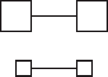
Baldwin’s i. 1. Illusion in which a line connecting two large squares appears shorter than a line connecting two smaller squares (Fig. I1). 2. Illusion in which a dot placed halfway between a large disc and a smaller disc appears to be nearer the large one.
café wall i. An illusion induced by a pattern of alternating columns of black and white rectangles (or squares) placed in such a way that the lines that they compose do not appear to be parallel. Syn. Munsterberg illusion. A variant of this illusion consists of hollow squares without alternating colour and is called a ‘hollow square illusion’.
Cornsweet i. See effect, Craik–O’Brien– Cornsweet.
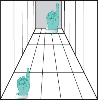
corridor i. Illusion in which images of equal size in a perspective figure of a corridor, appear to be of different sizes. The figure that seems further away appears larger than the one in the foreground (Fig. I2).
Craik–Cornsweet i. See effect, Craik–O’Brien–Cornsweet.
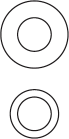
Delboeuf i. Illusion in which a circle surrounded by a slightly larger concentric circle appears larger than another circle of the same size surrounded by a much larger concentric circle (Fig. I3).
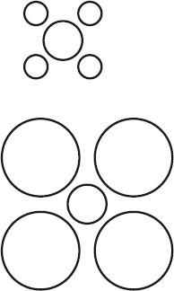
Ebbinghaus i. Illusion in which a circle usually appears larger when surrounded by smaller circles than by larger circles (Fig.I4).
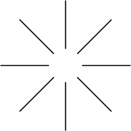
Ehrenstein’s brightness i. Illusion in which the erased area at the intersection of radial (or horizontal and vertical) lines appears to be brighter than the background and with an illusory contour (Fig. I5).
floating-finger i. Illusion noted when fixating a point in the distance while the forefingers of each hand are held horizontally about 30 centimetres in front of the eyes, with the fingertips nearly touching. A small, disembodied finger with two tips appears floating in between and can be shortened or lengthened by varying the distance between the fingertips. It is a peculiar illustration of physiological diplopia (Fig. I6).
frequency doubling i. Illusion in which a grating pattern appears to have twice as many black and white bars as it actually has.

This happens when a sinusoidal grating with a low spatial frequency (less than 4 c/deg) flickers in a counterphase fashion (i.e. light bars become dark and vice versa) at a high temporal frequency (more than 15 Hz). This type of stimulation is assumed to stimulate the non-linear mechanism within the magnocellular visual system.
See perimetry, frequency doubling.
Helmholtz i. See irradiation.
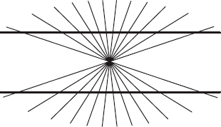
Hering’s i. Illusion in which a pair of parallel lines appear bent when placing diagonal lines across them. This illusion is most noticeable when radiating lines are crossing two parallel lines on opposite sides of the point of radiation. In this case, the two parallel lines appear to bend away from each other (Fig. I7).
Hermann’s i. See Hering–Hermann grid.
hole in the hand i. See test, hole in the hand.
hollow square i. See illusion, café wall.
horizontal-vertical visual i. Illusion in which the vertical line appears longer than the horizontal line when two lines of equal length are placed with the vertical line at the midpoint of the horizontal.
See illusion, top hat.
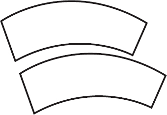
Jastrow i. Illusion in which two identical curved and tapering ring segments placed one above the other appear unequal in size, the band nearer the centres of curvature appearing to be the longest (Fig. I8).
Kundt’s i. Illusion occurring when one attempts to bisect a horizontal line with only one eye and the segment on the temporal side of the visual field is then larger than the other.
moon i. Illusion in which the moon appears much larger at the horizon than when viewed
high in the sky. In fact, the actual size of the moon remains constant as does its distance from the earth. One possible explanation is that at the horizon there are many other cues in the field of view (e.g. houses, mountains) that make the moon appear to be much closer than when it is high in the sky and thus should be larger.
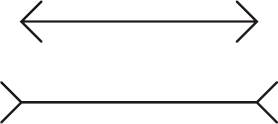
Müller–Lyer i. Illusion in which a line with outgoing fins on both ends appears longer than another of equal length but with arrowheads on both ends (Fig. I9).
Munsterberg’s i. See illusion, café wall.
oculogyral i. Illusion of apparent movement of viewed objects when the body is subjected to rotary acceleration. The initial apparent movement is opposite to that of the direction of rotation of the body and is followed by an apparent movement in the same direction.
Oppel–Kundt i. Illusion in which a divided, interrupted or filled area appears to be larger than an empty area of equal size.
optical i. See illusion, visual.
Orbison i. Illusion of a distorted geometric figure such as a square or a circle drawn on a background of radiating lines or concentric lines.
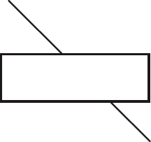
Poggendorff’s i. Illusion in which two visible portions of a diagonal line overlaid by a rectangle do not appear to be continuous (Fig. I10).
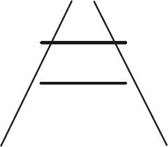
Ponzo i. Illusion in which two parallel lines of equal length do not appear equal when they are surrounded by two radiating straight lines, one on each side. The parallel line nearer the point of radiation appears to be longer (Fig. I11).
Schroeder’s staircase visual i. See Schroeder’s staircase.
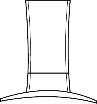
top hat i. Illusion in which a top hat drawn with equal vertical and horizontal dimensions appears to be much greater vertically than horizontally. It is closely related to the horizontal-vertical illusion (Fig. I12).
See illusion, horizontal-vertical visual.
visual i. Perception of an object or a figure that does not correspond to the actual physical characteristics of the stimulus. Syn. optical illusion; geometrical optical illusion.
waterfall i. See after-effect, waterfall.
Wundt’s i. Illusion in which a pair of parallel lines appear bent towards each other when crossed by lines radiating from two points, one on each side of the parallel lines.
See illusion, Hering’s.
Zollner’s i. Illusion in which a series of parallel lines appear to converge or diverge from
each other when crossed by short diagonal lines.
illusory contours See contour.
image A picture of an object formed by a lens, a mirror or other optical system.
aerial i. An image found in space and not on a screen, such as the image viewed in indirect ophthalmoscopy.
after-i. See after-image.
axial point i. The point of intersection of an image with the optical axis.
catadioptric i. Image formed by both reflecting and refracting surfaces.
See system, catadioptric.
catoptric i. Image formed by specular reflection, either from a mirror or by reflection at refracting surfaces such as the optical surfaces of the eye, which form the Purkinje–Sanson images.
corneal i. Catoptric image formed by either the anterior or posterior surface of the cornea. They are also called the first and second Purkinje–Sanson images.
dioptric i. An image formed by a refracting surface as distinguished from a catoptric image.
direct i. A virtual image such as the erect image seen in direct ophthalmoscopy.
double i. A pair of images obtained either optically through a doubling system or due to diplopia.
eidetic i. Visual perception arising from the imagination of the subject or what has previously been seen, and not from immediate retinal stimulation. That image may last from a few seconds to several minutes and appears to be located in front of the eyes.
entoptic i. Visual sensation arising from stimuli within the eye and perceived as in the external world. Examples: muscae volitantes; phosphene. Syn. entoptic phenomenon.
See angioscotoma; arcs, blue; entoptoscope, blue field; floaters; Haidinger’s brushes; spot, Maxwell’s.
erect i. Image that is not inverted with respect to the object such as a virtual image produced by a concave lens.
See images, Purkinje–Sanson.
extraordinary i. See birefringence.
false i. 1. The retinal image in the deviating eye in strabismus. It is less well defined than the true image. 2. See image, ghost. See image, true.
ghost i. 1. Unwanted image as may be formed by internal reflection in a lens or an optical system. These images are sometimes annoying to spectacle wearers, and even to observers as they detract from the appearance of the spectacle lens or hide the wearer’s eyes behind a veil. The intensity of ghost images is diminished by antireflection coatings. 2. The faint image seen in monocular diplopia. Syn. false image.
See Fresnel’s formula; lens flare; light, stray; mirror, front surface.
indirect i. A real image, such as the inverted image seen in indirect ophthalmoscopy.
inverted i. Image that is upside down and right for left with respect to its object. Syn. reversed image.
See images, Purkinje–Sanson.
i. jump See jump.
ocular i. 1. The retinal image. 2. The image formed by the refracting system of the eye, disregarding the presence or the position of the retina.
perceptual i.; psychic i. See image, visual.
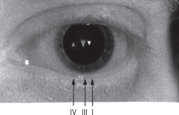
Purkinje–Sanson i’s. Catoptric images produced by reflection from the optical surfaces of the eye. The first image is reflected by the anterior surface of the cornea, the second image by the posterior surface of the cornea, the third image by the anterior surface of the crystalline lens and the fourth image by the posterior surface of the crystalline lens. Only the fourth image is inverted. The third is the largest but the first is by far the brightest (Fig. I13). During accommodation, the third image becomes smaller while the size of the fourth diminishes only a little. Purkinje–Sanson images are used to measure or calculate various optical dimensions of the eye, to establish angle alpha or lambda and to contribute to some diagnostic tests of strabismus (e.g. Hirschberg’s method; Krimsky’s method). Syn. Purkinje images.
See axis, optical; ophthalmophakometer; phacoscope.
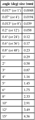
Table I1
Approximate relationship between the retinal image size of an emmetropic eye with a power of 60 D and the angular subtense of a distant object
| angle (deg) size (mm) | |
| 0.017° (or 1’) | 0.0048 |
| 0.07° (or 4’) | 0.0194 |
| 0.013° (or 8’) | 0.039 |
| 0.2° (or 12’) | 0.058 |
| 0.4° (or 24’) | 0.12 |
| 0.6° (or 36’) | 0.17 |
| 0.8° (or 48’) | 0.23 |
| 1° | 0.29 |
| 2° | 0.58 |
| 3° | 0.87 |
| 4° | 1.16 |
| 5° | 1.45 |
| 6° | 1.75 |
| 8° | 2.33 |
| 10° | 2.91 |
| 12° | 3.49 |
| 15° | 4.36 |
real i. An image that can be formed on a screen.
See focus, principal; object, real.
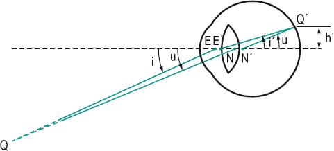
retinal i. Image formed on the retina by the optical system of the eye. The size of the retinal image h’ of a distant object subtending angle u in an emmetropic eye is equal to

where h’ is in metres, u in radians and the power of the eye F in dioptres. The formula is only valid for small angles (Fig. I14). Example: a distant object subtends an angle of 5° viewed by an emmetropic eye of power 60 D (π is equal to 3.1416)
reversed i. See image, inverted.
i. shell The curved surface containing either all the sagittal or all the tangential foci corresponding to a given object plane.
See astigmatism, oblique.
stabilized retinal i. See stabilized retinal image.
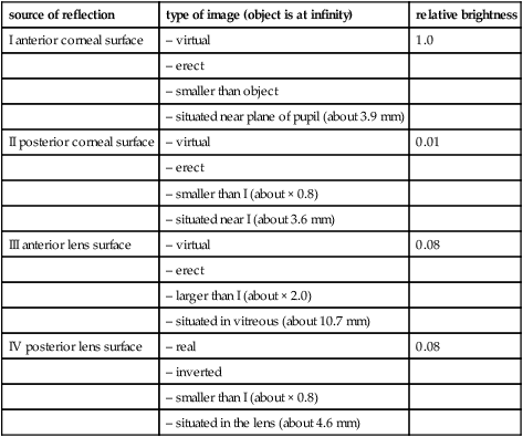
Table I2
Purkinje-Sanson images (all figures are calculated and rounded off and all distances are referred to the anterior corneal pole)
| source of reflection | type of image (object is at infinity) | relative brightness |
| I anterior corneal surface | – virtual | 1.0 |
| – erect | ||
| – smaller than object | ||
| – situated near plane of pupil (about 3.9 mm) | ||
| II posterior corneal surface | – virtual | 0.01 |
| – erect | ||
| – smaller than I (about × 0.8) | ||
| – situated near I (about 3.6 mm) | ||
| III anterior lens surface | – virtual | 0.08 |
| – erect | ||
| – larger than I (about × 2.0) | ||
| – situated in vitreous (about 10.7 mm) | ||
| IV posterior lens surface | – real | 0.08 |
| – inverted | ||
| – smaller than I (about × 0.8) | ||
| – situated in the lens (about 4.6 mm) |
true i. The retinal image in the normally fixating eye in strabismus.
virtual i. One from which refracted or reflected rays appear to have come. This image can be seen but it is not an actual image and cannot be formed on a screen. Examples: the image seen in a plane mirror; the image seen in the cornea.
See focus, principal; object, virtual.
Stay updated, free articles. Join our Telegram channel

Full access? Get Clinical Tree


