Fresnel Optics
Merton C. Flom
Anthony J. Adams
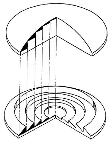 Fig. 1. Principle of a Fresnel lens. Refracting or bending power of the lens depends primarily on the relative angle between its surfaces and not on physical thickness. The small shaded lenslets are the effective refracting elements of the planoconvex lens shown in the upper half of the figure. They are represented in their equivalent Fresnel lens form as small shaded prismlets in the lower half of the figure. |
Molded glass Fresnel lenses are now widely used as signal and head lamps where large diameter and relatively light weight are required. Narrow grooves, which are necessary for good optical quality, cannot be ground and polished by conventional means; unfortunately, the high surface tension of glass does not permit fine details of a mold to be reproduced. Consequently, molded glass Fresnel lenses are of poor optical quality. Plastics have made possible the molding of narrow-grooved Fresnel lenses which have highly polished and accurate surfaces. These narrow-grooved plastic lenses have been used primarily in the viewing screens of microscopes and micro film readers. The emergence of high quality dies and new plastics which has permitted the production of Fresnel lenses and prisms.
THE FRESNEL PRINCIPLE
The basis of the Fresnel principle is to remove most of the nonrefracting portions of a conventional lens; this process results in a relatively lightweight, large diameter optical element. Since light is refracted (bent) only at the surface of an optical element and travels in a straight line elsewhere, the refracting power of a lens or prism depends primarily on the relative angle between the two refracting surfaces. The angle between the surfaces is unchanged across a prism, but changes across a lens. A lens, then, can be considered as a series of prisms of increasing apex angle as one moves away from the optical center of the surface. Indeed, Fresnel lenses are most commonly created by narrow, flat-surface, prism grooves of increasing apex angle.
The Fresnel principle for a prism with flat surfaces is illustrated in Figure 2. It is a common clinical observation that the smaller the spectacle frame, the thinner is the base of a conventional prism. Figure 2 shows that reducing the base-apex dimension of a prism from 40 mm to 20 mm reduces the base thickness from 10 mm to 5 mm. Reducing the prism to the very small size of only 4 mm would result in a base thickness of only 1 mm. In each case, the deviating power of the prism is the same since the apex angle is constant. If the base-apex size were reduced to only 2 mm, it is seen in the shaded area of Figure 2 that the base of the prism would be only 0.5 mm thick. A Fresnel prism can be imagined to be a series of small prisms lying adjacent to each other on a platform creating a thin membrane.
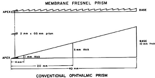 Fig. 2. A Fresnel prism, much thinner than a conventional ophthalmic prism of the same power, can be imagined to be a series of small plastic prisms (see shaded prisms) lying adjacent to each other on a thin platform of plastic. (Modified from Jampolsky A, Flom MC, Thorson JC: Membrane Fresnel prisms: A new therapeutic device. In Fells P (ed): Proceedings of the First Congress of the International Strabismological Association. London: Kimpton, 1971.) |
The Fresnel prism in the example has the same deviating power as a conventional prism of the same material; however, the Fresnel prism is only 1 mm thick (0.5 mm prism base and 0.5 mm platform), one tenth the thickness of the conventional prism of the same power.
A Fresnel lens consists of similar flat ridges in the form of concentric rings. The shaded area of Figure 3 represents the Fresnel equivalent of a conventional planoconvex lens. It is important to notice that the narrower the grooves are, the more closely each facet approaches a prism with a flat surface.
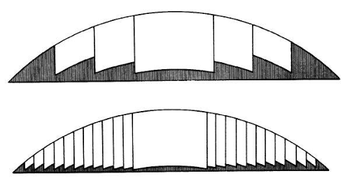 Fig. 3. Fresnel equivalents of a conventional planoconvex lens. |
TYPES OF PRISMS AND LENSES
The first ophthalmic applications of the Fresnel principle were prisms. Hard acrylic prisms of relatively high prismatic power (more than 10Δ) were developed primarily for the optical treatment of strabismus and were designed to clip onto existing glasses (manufactured by Essilor International, Paris and Universal Optical Co., Dallas, TX)2 (Fig 4). The principle advantage of the Fresnel wafer prism is the reduction in weight when compared to conventional prisms of the same power. The principle disadvantage is the conspicuous Fresnel grooves.
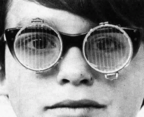 Fig. 4. Clip-on wafer prisms of 15Δ base out each eye. |
In 1970, thin flexible membrane Fresnel prisms were developed for ophthalmic use (Optical Sciences Group, Inc., San Rafael, CA)3. The membranes are made of clear polyvinyl chloride and are designed to be applied without adhesive to the back surface of a conventional ophthalmic lens. Because the membrane is extremely thin (0.8 mm) and the grooves very narrow (16 per inch), they are cosmetically superior to the hard acrylic wafer prisms. Their relatively large (64 mm) diameter allows them to be cut to conform to the shape of most spectacle carrier lenses (Fig 5). The refractive index (1.525) is very close to that of optical crown glass. A range of powers, from 0.5Δto 30Δ enables them to be used for the optical treatment of both heterophoria and strabismus. These prisms have been used clinically as a permanent correction and as a direct substitute for the conventional prism; however, they have found most common application in temporary use (eg, for diagnostic use or where the prism requires frequent changing).
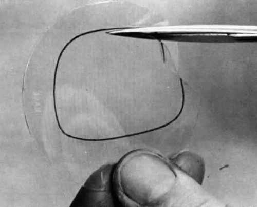 Fig. 5. Fresnel membrane prism of 12Δ being cut out to correspond to the shape of a patient’s glasses. |
Flexible Fresnel membrane aspheric lenses have also been developed in powers up to 20 diopters (Optical Sciences Group, Inc., San Rafael, CA). They are similar in physical characteristics to the membrane prisms. For low spherical powers there are approximately 16 grooves per inch; they increase to approximately 80 per inch for the 14-D lens.
The Fresnel membrane lenses and prisms are designed for in-office application; they are cut with scissors to the appropriate shape for adhesiveless application to the back surface of a conventional glass or plastic spectacle lens. Both the membrane and the spectacle lens are immersed in a bowl of water, and the smooth side of the membrane is slid against the back surface of the spectacle lens. When air bubbles or dust particles have been removed from between the Fresnel and the lens and the membrane is properly positioned on the lens, the combination is removed from the water and excess moisture is gently squeezed out. Several hours later the residual layer of water completely evaporates through the polyvinyl chloride (PVC) leaving the membrane tightly adhering to the spectacle lens carrier. Membranes applied in this fashion remain attached to the carrier lens indefinitely, and in the event that they need to be removed, they can be peeled off, starting at the edge. The membrane adheres to the lens for the same reason that two fiat pieces of glass bond together when the air layer between them has been removed. This glueless application is not injurious to the spectacle lens, and successive Fresnel membrane applications to the same carrier lens are possible.
Fresnel membranes applied to the back surface of an ophthalmic lens have been shown to provide added eye safety from shattered glass following lens fracture4. The membrane seems to act as a barrier between the fragments and the eye (Fig 6).
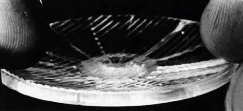 Fig. 6. Fresnel membrane prism pressed onto the back surface of a spectacle lens provides added eye safety from shattered glass following lens fracture by acting as a barrier between the lens fragments and the eye. (From Kors KK, Flom MC, Adams AJ: Fracturing and safety properties of glass spectacle lenses having back surface vinyl membranes. Am J Optom 49:471, 1972.) |
OPTICAL CONSTRUCTION
Fresnel optics are made either by injection molding or by the more precise compression molding of plastics. In a lens mold the grooves are usually cut with a precision diamond tool that forms a concentric pattern in the surface. The tool has a straight cutting edge; over the very small width of one groove the flat surface is a close approximation to a curved surface, ie, the arc and chord are almost indistinguishable. Successive grooves away from the center of a concentric engraving have slightly increased apex angles for lenses. The angle of each successive groove is independently set so that virtually any spherical or aspheric Fresnel surface can be generated. Present technology employs computer control of the lathe cutting tool and, hence, also the groove angles. The production of aspheric
Fresnel surfaces is, unlike that for conventional aspheric lens surfaces, no more difficult or expensive than production of spherical surfaces. This fact is important to the Fresnel lens designer because he can utilize the flexibility of Fresnel lens surface design to eliminate or reduce many optical aberrations.
“Groove by groove” design has been used successfully in industrial applications where specific aberrations needed to be eliminated. Industrial Fresnel lenses are commonly produced by grooving one surface of a slab of flat material. Here the degree of freedom of lens “bending” is lost in the design of aberration-free optics. If the Fresnel principle is applied to the design of both surfaces of a lens in order to recapture the bending factor, objectionable moiré patterns result from the optical interference of the two groove patterns (ie, similar to the effect one gets when viewing one picket fence behind another).
When a Fresnel lens is made of thin flexible material with the grooves in one surface, then the resulting membrane “lens” can be applied to a curved optical surface of a conventional lens thus taking advantage of the additional degree of freedom found in “bending” a lens. This method has been used in the application of Fresnel optics to ophthalmic prescriptions.
Ophthalmic Fresnel membrane lenses and prisms are made from lens or prism molds which are cut in metal (commonly brass). Individual molds are then mounted together into a base or matrix of 14 different molds. Sheets of specially formulated plasticized PVC (plasticized in order to soften the PVC and cause it to adhere to a spectacle carrier lens) are pressed into the mold at high temperature and pressure. After cooling, the lenses are sealed by local heat to a rigid frame which provides support for the membrane. At the time that individual membrane lenses are punched out with their rigid frame, the border of the lens is perforated to allow subsequent removal when the membranes are to be applied to the surface of a conventional spectacle lens.
PERFORMANCE
OPHTHALMIC PRISMS
Wafer prisms of hard acrylic plastic have been used for approximately 9 years. These prisms have been used almost exclusively to clip onto existing glasses. Flexible membrane Fresnel prisms (and lenses) have also been manufactured to press onto an existing ophthalmic lens.
The distortions of conventional prisms and Fresnel membrane prisms have been compared by Adams et al5. Their study covered a range of base curves (0 to 9 D) and angular fields of view (±20°). Five distortions described by Ogle6,7 were considered: horizontal magnification, vertical magnification, curvature of vertical lines, asymmetric horizontal magnification, and change in vertical magnification with horizontal angle (Fig 7) (Table 1).
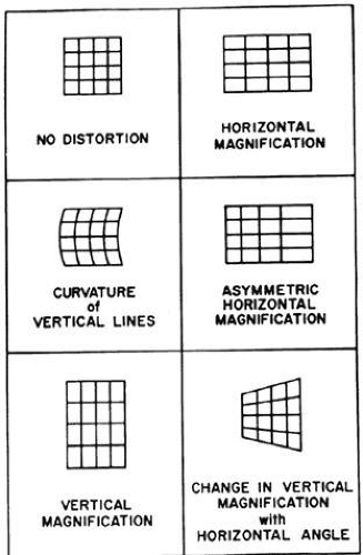 Fig. 7. The five distortions of a prism base left. (From Adams AJ, Kapash RI, Barkan E: Visual performance and optical properties of Fresnel membrane prisms. Am J Optom 48:289, 1971.) |
TABLE 1. Comparison of Conventional and Fresnel Prisms | ||||||||||||||||||
|---|---|---|---|---|---|---|---|---|---|---|---|---|---|---|---|---|---|---|
| ||||||||||||||||||
Except for horizontal and vertical magnification (ie, overall magnification), each distortion is reduced with increasing base curve up to 9 D for both conventional and Fresnel membrane prisms. There is little difference in these distortions for the two prism types; the Fresnel type is slightly better in two and slightly worse in one distortion.
For conventional prisms most of the distortions were reduced with high base curves (which are prescribed clinically for this reason), but horizontal and vertical magnification (ie, overall magnification) becomes quite large with increasing base curve. Figure 8 illustrates this point and also shows that the overall magnification created by Fresnel prisms is small and relatively unaffected by change in base curve.
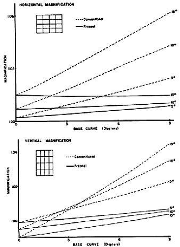 Fig. 8. Comparison of Fresnel and conventional prisms in inducing horizontal and vertical magnification. (From Adams AJ, Kapash RJ, Barkan E: Visual performance and optical properties of Fresnel membrane prisms. Am J Optom 48:289, 1971.) |
If a practitioner desires to prescribe a conventional prismatic correction that is greater in power for one eye than the other, then the consequences of an induced difference in retinal image size must be considered. For example, if a patient were to wear a 15Δconventional prism on a 9 D base curve on only one eye, there would be an induced image size difference of at least 5%. The same prism power and base curve in a Fresnel prism produces only approximately 1.5% image size difference.
Prismatic distortion and its correction have received much attention6,7,8,9. However, the oblique astigmatism and power error found in ophthalmic prisms are also important clinically. These aberrations have received little attention until Barkan and Kapash10 compared them in conventional and Fresnel prisms. Oblique astigmatism and spherical power vary across the surface of both Fresnel membrane prisms and conventional prisms. The rate of increase with viewing angle is less for Fresnel membrane prisms. However, astigmatism is usually higher at any given viewing angle for the Fresnel prism. Interestingly, the astigmatism across a Fresnel prism is almost constant with the viewing angle; therefore, a cylindric correction incorporated into a carrier lens could offset most of the oblique astigmatism created by a Fresnel membrane prism. However, the spherical error for any viewing angle is always less in a Fresnel prism than in a conventional prism. For example, a conventional 15Δprism ground on a 9 D base curve varies in induced spherical power from + 1.25 D for a viewing angle of 20° toward the base to -0.75 D for a viewing angle of 20° toward the apex, a total of 2 D of power variation across a 40° span of the lens. The equivalent Fresnel membrane lens varies from +0.75 D to -0.50 D across the same angle giving 1.25 D of power variation.
Stay updated, free articles. Join our Telegram channel

Full access? Get Clinical Tree


