9 Clinical Masking It seems reasonable to assume that sounds presented to the right ear are heard by the right ear, and that sounds presented to the left ear are heard by the left ear. However, this is not necessarily true. In fact, it is common to find that the sound being presented to one ear is actually being heard by the opposite ear. This phenomenon is called cross-hearing or shadow hearing. To avoid confusion it is customary to call the ear currently being tested the test ear (TE) and to call the opposite ear, which is the one not being tested, the nontest ear (NTE). Cross-hearing results in a false picture of the patient’s hearing. Even the possibility that the sounds being presented to the TE are really being heard by the NTE causes the outcome of a test to be suspect, at best. This chapter explains why this situation occurs, how it is recognized, and the manner in which the NTE is removed from the test. Suppose we know for a fact that a patient’s right ear is essentially normal and that his left ear is completely deaf. We would expect the audiogram to show airand bone-conduction thresholds of perhaps 0 dB HL to 10 dB HL for the right ear and “no response” symbols for both air-conduction and bone-conduction at the maximum testable levels for the left ear, as in Fig. 9.1a. However, this does not occur. Instead, the actual audiogram will be more like the one shown in Fig. 9.1b. Here the thresholds for the right ear are just as expected. On the other hand, the left air-conduction thresholds are in the 55 to 60 dB HL range, and the left bone-conduction thresholds are the same as for the right ear. How can this be if the left ear is deaf? Let us first address this question for the air-conduction signals. Since the patient cannot hear anything in the left ear, the level of an air-conduction test tone presented to that ear will be raised higher and higher. Eventually, the tone presented to the deaf ear will be raised so high that it can actually be heard in the opposite ear, at which point the patient will finally respond. The patient’s response to the signal directed to his deaf ear (the TE) is the result of hearing that signal in the other ear (the NTE). Thus, the left ear’s threshold curve in Fig. 9.1b is due to cross-hearing, and is often called a shadow curve. In order for the tone to be heard in the NTE it must be possible for a signal presented to one ear to be transmitted across the head to the other ear. This phenomenon is called signal crossover. The intensity of the sound reaching the NTE is less than what was originally presented to the TE because it takes a certain amount of energy to transmit the signal across the head. The number of dB that are “lost” in the process of signal crossover is called interaural attenuation (IA) (Chaiklin 1967). In Fig. 9.1b, the patient’s right air-conduction threshold at 1000 Hz is 10 dB HL. Even though his left ear is completely deaf, he also responded to a 1000 Hz tone presented from the left earphone at 60 dB HL. This means that the 60 dB HL tone presented to the left ear must have reached a level of 10 dB HL in the right ear. Consequently, IA at 1000 Hz in this case must be 50 dB (60 dB – 10 dB = 50 dB). Similarly, the amount of IA at 4000 Hz in this case is 55 dB (60 dB – 5 dB = 55 dB) Crossover occurs when the signal is physically present in the opposite ear, whereas cross-hearing occurs only when it is audible. The distinction is clarified using the following example based on our hypothetical patient: The level of the 1000 Hz tone reaching this person’s right (nontest) ear will always be 50 dB less than the amount presented from the left earphone due to IA. Consider these three cases:
 Cross-Hearing and Interaural Attenuation
Cross-Hearing for Air-Conduction
dB HL at left earphone | – IA | = dB HL present at right cochlea |
(a) 60 dB | – 50 dB | = 10 dB (at threshold) |
(b) 80 dB | – 50 dB | = 30 dB (20 dB SL) |
(c) 55 dB | – 50 dB | = 5 dB (5 dB below threshold) |
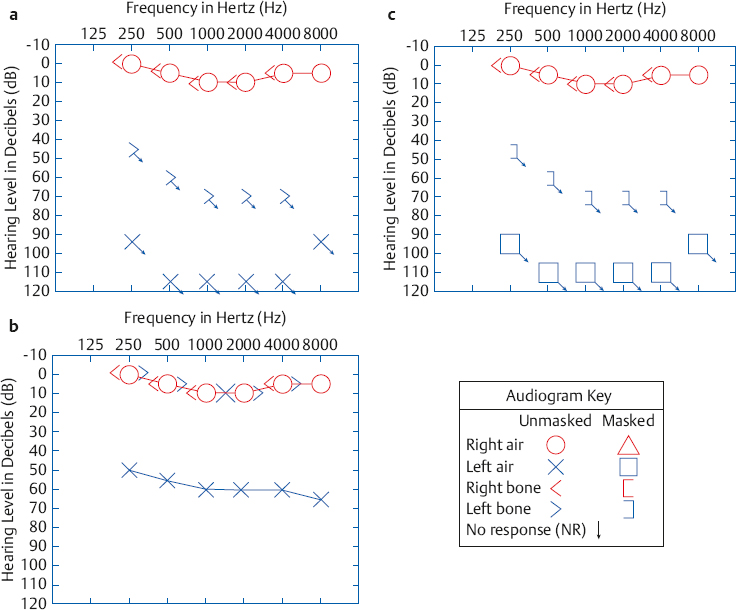
Fig. 9.1 (a) Imagined (incorrect) audiogram without cross-hearing for a patient who is deaf in the left ear, showing “no response” for air-conduction or bone-conduction signals. (b) Actual audiogram for such a patient, reflecting the fact that the signals presented to the left side were heard in the right ear by cross-hearing. (c) Audiogram obtained when the left thresholds are retested with masking noise in the right ear.
These three examples are shown graphically in Fig. 9.2. In (a) the tone reaches the right ear at 10 dB HL, and is heard because this is the right ear’s threshold. In (b) the tone reaches the right ear at 30 dB HL and is heard because this level is 20 dB above the right ear’s threshold (20 dB SL). In both of these cases signal crossover resulted in cross-hearing. However, the tone in (c) reaches the right ear at only 5 dB HL, which is 5 dB below threshold and is thus inaudible. Here, there is crossover because the signal is present in the NTE but there is no cross-hearing because it is below threshold.
Assuming the bone-conduction threshold remained at 10 dB HL, how would cross-hearing be affected if the IA was changed from 50 dB to another value, such as 40 dB or 60 dB? Some time with paper and pencil will reveal that the cross-hearing situation would change considerably.
Cross-Hearing for Bone-Conduction
The right and left bone-conduction thresholds are the same in Fig. 9.1b even though the right ear is normal and the left one is deaf. The implication is that the bone-conduction signal presented to the left side of the head is being received by the right ear. This should come as no surprise, since we found in Chapter 5 that a bone-conduction vibrator stimulates both cochleae about equally. From the cross-hearing standpoint, we may say that there is no interaural attenuation (IA = 0 dB) for bone-conduction. Thus, the right and left bone-conduction signals result in the same thresholds because they are both stimulating the same (right) ear.
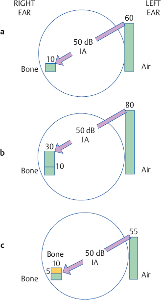
Fig. 9.2 (a–c) Three crossover conditions (see text).
Overcoming Cross-Hearing with Masking Noise
The above example demonstrates that there are times when the NTE is (or at least may be) responding to the signals intended for the TE. How can we stop the NTE from hearing the tones being presented to the TE? First, consider an analogy from vision testing. Looking at an eye chart with two eyes is akin to the cross-hearing issue. We all know from common experience that to test one eye at a time the optometrist simply blindfolds the nontest eye. In other words, one eye is tested while the other eye is masked. In effect, we do the same thing in audiology, except that the auditory “blindfold” is a noise that is directed into the NTE. The noise in the NTE stops it from hearing the sounds being presented to the TE. Just as the nontest eye is masked by the blindfold, so is the nontest ear masked by the noise.
Returning to our example, Fig. 9.1c shows the results obtained when the air- and bone-conduction thresholds of the left (test) ear are retested with appropriate masking noise in the right (nontest) ear. The thresholds here are shown by different symbols than the ones in frames (a) and (b), to distinguish them as masked results. Because the left ear in this example is completely deaf, the masked thresholds have downward-pointing arrows indicating no response at the maximum limits of the audiometer. Notice that the masked results in frame (c) are at the same hearing levels as the ones in frame (a). The important difference is that the unmasked thresholds in frame (a) could never have actually occurred because of cross-hearing. Note the dramatic difference between the unmasked results in frame (b) and the patient’s real hearing status, revealed by the masked thresholds in frame (c).
We see that when cross-hearing occurs it is necessary to retest the TE while directing a masking noise into the NTE. The purpose of the masking noise is to prevent the NTE from hearing the tone (or other signal) intended for the TE. Thus, the issue of whether cross-hearing might be occurring is tantamount to the question, is masking (of the NTE) necessary?
Principal Mechanism of Crossover
Signal crossover (and therefore cross-hearing) for bone-conduction signals obviously occurs via a bone-conduction route, as depicted in Fig. 9.3a. It occurs because a bone-conduction signal is transmitted to both cochleae.
Because crossover for air-conduction requires a reasonably substantial signal to be produced by the earphone (recall that interaural attenuation was ~ 50 dB in the prior example), common sense seems to suggest that air-conduction signals might reach the opposite ear by an air-conduction route. This might occur by sound escaping through the earphone cushion on the test side, traveling around the head, and then penetrating the earphone cushion on the non-test side. Alternatively, earphone vibration on the test side might be transmitted via the headset to the earphone on the nontest side. In either of these two scenarios, the signal from the test side would enter the ear canal of the NTE, that is, as an air-conduction signal. As compelling as these explanations may seem, they are not correct. It has been shown repeatedly that the actual crossover route for air-conduction signals occurs principally by bone-conduction to the cochlea of the opposite ear (Sparrevohn 1946; Zwislocki 1953; Studebaker 1962), as depicted in Fig. 9.3b.
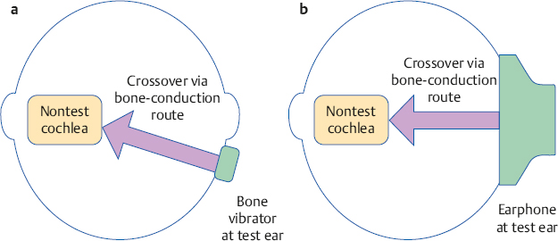
Fig. 9.3 Signal crossover and cross-hearing occur via the bone-conduction route to the opposite cochlea, as indicated by the arrows for both (a) bone-conduction and (b) air-conduction.
Interaural Attenuation for Air-Conduction
Cross-hearing of a test signal renders a test invalid. We must therefore identify cross-hearing whenever it occurs so that we can mask the NTE. The cost of failing to do so is so great that we want to employ masking every time that cross-hearing is even possible. Once we have obtained the unmasked audiogram, we are left with the following question: Is the air-conduction signal being presented to the TE great enough to cross the head and reach the bone-conduction threshold of the NTE? In other words, is this difference greater than the value of interaural attenuation? The corollary problem is to determine the IA value.
Interaural attenuation for air-conduction using supra-aural earphones typical of the type used in audiological practice has been studied using a variety of approaches (Littler, Knight, & Strange 1952; Zwislocki 1953; Liden 1954; Liden, Nilsson, & Anderson 1959a; Chaiklin 1967; Coles & Priede 1970; Snyder 1973; Smith & Markides 1981; Sklare & Denenberg 1987). Fig. 9.4 shows the mean IA values found in four of these studies, as well as the maximum and minimum amounts of IA obtained across all four studies. Average IA values are ~ 50 to 65 dB, and there is a general tendency for IA to become larger with frequency. The range of IA values is very wide, and the means are much larger than the minimum IA values. Consequently, we cannot rely on average IA values as a red flag for cross-hearing in clinical practice because many cases of cross-hearing would be missed in many patients on the lower side of the IA range. For this reason it is common practice to use minimum IA values to identify possible cross-hearing, that is, to decide when masking may be needed. As anticipated from the figure, the minimum IA value typically suggested to rule out crossover for clinical purposes is 40 dB (Studebaker 1967; Martin 1974, 1980).
Interaural Attenuation for Insert Earphones
The IA values just described are obtained using typical supra-aural audiometric earphones, such as Telephonics TDH-49 and related receivers. In contrast, insert earphones such as Etymotic ER-3A and EARtone 3A receivers provide much greater amounts of IA (Killion, Wilber, & Gudmundsen 1985; Sklare & Denenberg 1987). This occurs because the amount of IA is inversely related to the contact area between the earphone and the head (Zwislocki 1953), and the contact area between the head and earphone is much less for insert receivers than it is for supra-aural earphones. Fig. 9.5 shows some of the results obtained by Sklare and Denenberg (1987), who compared the IA produced by TDH-49 (supra-aural) and ER-3A (insert) earphones on the same subjects. They found that mean IA values were from 81 to 94+ dB up to 1000 Hz and 71 to 77 dB at higher frequencies, for insert receivers.
As already explained, we are most interested in the minimum IA values, which are shown by the bottoms of the error lines in the graph. Sklare and Denenberg found that insert receivers produced minimum IA values of 75 to 85 dB at frequencies up to 1000 Hz, and 50 to 65 dB above 1000 Hz. This is substantially greater than the minimum IA values found for the TDH-49 earphone, which ranged from 45 to 60 dB.
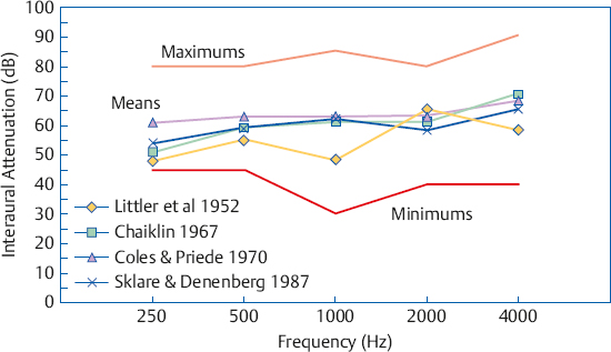
Fig. 9.4 Interaural attenuation values for supra-aural earphones from four representative studies. Lines with symbols are means for each study. The “minimum” and “maximum’’ lines show the smallest and largest IA values across all four studies.
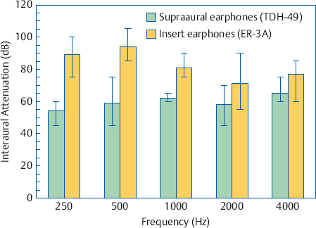
Fig. 9.5 Interaural attenuation for TDH-49 (supra-aural) versus ER-3A (insert) earphones. Bars show means and error lines show ranges. Some actual values were higher than shown. (This occurred because some individual IA values were higher than the limits of the equipment.) (Based on the data of Sklare and Denenberg [1987]).
It should be noted that the IA values just described were obtained using insert receivers that were inserted to the proper depth into the ear canal. Insert receivers produce much less IA when their insertion into the ear canal is shallow compared with deep (Killion et al 1985).
Interaural Attenuation for Bone-Conduction
It is commonly held that interaural attenuation is 0 dB for all bone-conduction signals, but this concept requires qualification. There is essentially no IA for bone-conduction signals presented by a bone-conduction vibrator using frontal placement (Studebaker 1967). However, IA for the more commonly used mastoid placement of the bone-conduction oscillator depends on the frequency being tested, and is also variable among patients (Studebaker 1964, 1967). Interaural attenuation values for bone-conduction signals presented at the mastoid are ~ 0 dB at 250 Hz and rise to ~ 15 dB at 4000 Hz (Studebaker 1967). The author’s experience agrees with others’ clinical observations that IA for bone-conduction varies among patients from roughly 0 to 15 dB at 2000 and 4000 Hz (Silman & Silverman 1991).
 Clinical Masking
Recall that masking per se means to render a tone (or other signal) inaudible due to the presence of a noise in the same ear as the tone. Thus, masking the right ear means that a noise is put into the right ear, so that a tone cannot be heard in the right ear. Clinical masking is an application of the masking phenomenon used to alleviate cross-hearing. In clinical masking we put noise into the nontest ear because we want to assess the hearing of the test ear. In other words, the masking noise goes into the NTE, and the test signal goes into the TE. Also, the noise is delivered to the NTE by air-conduction, regardless of whether the TE is being tested by air- or bone-conduction. These rules apply in all but the most unusual circumstances. The kinds of masking noises used with various test signals are covered in a later section. In the meantime, it is assumed that the appropriate masking noise is always being used.
The meaning is clear when an audiologist says that she will “retest the left bone-conduction threshold with masking noise in the right ear.” However, masking terminology is usually more telegraphic. As such, it suffers from ambiguity and can be confusing to the uninitiated. It is therefore worthwhile to familiarize oneself with typical masking phrases and what these really mean. Unmasked air-conduction (or just unmasked air) refers to an air-conduction threshold that was obtained without any masking noise. Similarly, unmasked bone-conduction (or unmasked bone) means a bone-conduction threshold obtained without any masking noise. For example, unmasked right bone means the bone-conduction threshold of the right ear that was obtained without any masking noise.
Masked air-conduction (or masked air) refers to an air-conduction threshold (in the TE) that was obtained with masking noise in the opposite ear. Masked bone-conduction (masked bone) denotes a bone-conduction threshold obtained with masking noise in the NTE. Thus, masked right air is referring to the air-conduction threshold of the right ear that was obtained while masking noise was being presented to the left (nontest) ear. By the same token, masked left bone means the bone-conduction threshold of the left ear that was obtained with masking noise in the right ear.
The process of masking for air-conduction (masking for air) means to put masking noise into the NTE while testing the TE by air-conduction. Likewise, the operation of masking for bone-conduction (masking for bone) means to put masking noise into the NTE while testing the TE by bone-conduction.
Instructions for Testing with Masking
The first step in clinical masking is to explain to the patient what is about to happen and what she is supposed to do. The very idea of being tested with “noise in your ears” can be confusing to some patients, especially when they are being evaluated for the first time. The author has found that most patients readily accept the situation when they are told that putting masking noise in the opposite ear is the same as an optometrist covering one eye while testing the other.
Noises Used for Clinical Masking
What kind of noise should be used to mask the non-test ear? The answer to this question depends on the signal being masked. If the signal being masked has a wide spectrum, such as speech or clicks, then the masker must also have a wide spectrum. (The student might wish to refer back to Chapter 1 to review the relevant physical concepts.) For example, masking for speech tests commonly uses white noise (actually broadband noise), pink noise, speech-shaped noise, or multitalker babble. Speech-shaped noise has a spectrum that approximates that of the long-term spectrum of speech. Multitalker babble is made by recording the voices of many people who are talking simultaneously, resulting in an unintelligible babble.
Complex noises (e.g., sawtooth noise) composed of a low fundamental frequency along with many harmonics were also used in the past. These noises were poor and unreliable maskers, but one should be aware of them if only for historical perspective.
Pure tones can also be masked by wide-band noises, but this is not desirable. Recall from Chapter 3 that if we are trying to mask a given pure tone, only a rather limited band of frequencies in a wide-band noise actually contributes to masking that tone. This is the critical band (ratio). The parts of a wide-band noise that are higher and lower than the critical band do not help mask the tone, but they do make the noise sound louder. Thus, wide-band noise is a poor choice for masking pure tones because it is both inefficient and unnecessarily loud.
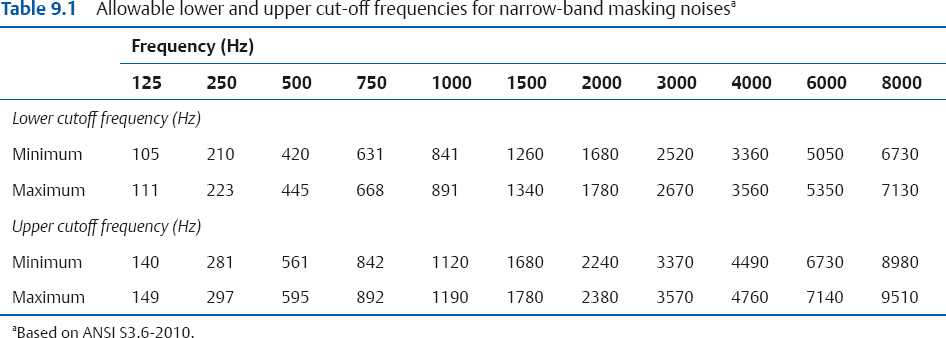
It would therefore seem that the optimal masking noises for pure tones would be critical bands. In practice, however, audiometers actually provide masking noise bandwidths that are wider than critical bands. This type of masking noise is called narrow-band noise (NBN). Audiometric NBNs may approximate bandwidths that are one-third octaves, one-half octaves, or other widths, and also vary widely in how sharply intensity falls outside the pass band (i.e., the rejection rate or steepness of the filter skirts). If an NBN is centered around 1000 Hz, then we can call this a 1000 Hz NBN; if it is centered around 2000 Hz, then it is a 2000 Hz NBN, and so forth. Table 9.1 summarizes the bandwidths for narrow-band masking noises specified by the ANSI S3.6-2010 standard.
When to Mask for Bone-Conduction
It might seem odd to discuss the bone-conduction masking rule before the one for air-conduction (AC) because this is the reverse of the order used to obtain unmasked thresholds. However, masked thresholds are tested in the opposite order, bone-conduction (BC) before AC. This is done because the rule for determining when masking is needed for air-conduction depends upon knowing the true bone-conduction thresholds. This means that if masking is needed for BC, it must be done first.
Bone-conduction testing presents us with a peculiar dilemma if we take it for granted that we always need to know which ear is actually responding to a signal. This is so because there is little if any IA for BC, so we rarely know for sure which cochlea is actually responding to a signal, no matter where the vibrator is placed. (Although mastoid placement is assumed throughout this book unless specifically indicated, it should be noted that the bone oscillator and both earphones are usually in place from the outset when forehead placement is used.)
This situation might seem to imply that masking should always be used whenever bone-conduction is tested. This approach was recommended by ANSI (2004) on the grounds that bone-conduction calibration is based on data that were obtained with masking the opposite ear.
However, this approach is not encouraged because it has several serious problems in addition to being unnecessarily conservative at the cost of wasted effort (Studebaker 1964, 1967). When bone-conduction thresholds are always tested with masking, the opposite ear will always be occluded with an earphone (both ears would probably be occluded with forehead placement). Thus, one cannot know when or where an occlusion effect occurs, or how large it is. But you need to know the size of the occlusion effect in the first place to calculate how much noise is needed for bone-conduction masking. In addition, always having the headset in place denies the clinician the ability to cross-check for bone-conduction oscillator placement errors, which cause falsely elevated bone-conduction thresholds. Also, placement problems can be clouded by an occlusion effect and/or by unwittingly attributing a higher threshold to the masking. The headset itself only exacerbates vibrator placement problems.
Another questionable technique relies on the Weber test to determine which ear is hearing a bone-conduction signal. These results are not sufficiently accurate or reliable for this purpose. Even its proponents admit that it is best to disregard unlikely Weber results (Studebaker 1967).
Because a given unmasked bone-conduction threshold could as likely be coming from either ear, a practical approach to deciding when to mask for bone-conduction is based on whether knowing which cochlea is actually responding affects how the audiogram is interpreted. In other words, when does it make a difference whether a given bone-conduction threshold is coming from one cochlea or the other?
A bone-conduction threshold should be retested with masking in the NTE whenever there is an air-bone-gap (ABG) within the test ear that is greater than 10 dB, that is, 15 dB or more, which may be written as:
ABG > 10 dB.
Because testing is done in 5 dB steps, this rule also can be stated this way: A bone-conduction threshold should be retested with masking in the NTE whenever the air-bone-gap (ABG) within the test ear is 15 dB or more, or
ABG ≥ 15 dB
This principle is shown schematically in Fig. 9.6a. This rule is consistent with the one recommended by Yacullo (1996, 2009), but differs from a stricter approach that calls for masking whenever the ABG is ≥ 10 dB (Studebaker 1964; ASHA 2005).1 The underlying concept for suggesting the less stringent masking criterion is as follows: The variability of a clinical threshold is usually taken to be ± 5 dB. Applying this principle to both the air- and bone- conduction thresholds for the same frequency allows them to be as much as 10 dB apart. Thus, for practical purposes, an ABG ≤ 10 dB is too small to be clinically relevant.
1 The > 10 dB (≥ 15) rule encouraged here was included in the first two editions of this text. It was changed to the Studebaker (1964) recommendation in the third edition because the ≥ 10 dB rule continued to be endorsed in the ASHA (2005) guidelines. However, the current edition is returning to the > 10 dB (≥ 15) rule because it is considered to be the more compelling approach.
With this in mind, consider the unmasked thresholds in the following example:
Right air conduction | 50 dB HL |
Left air conduction | 70 dB HL |
Bone conduction | 45 dB HL |
We do not know which ear is really responsible for the bone-conduction threshold of 45 dB. First consider the situation from the standpoint of the right ear. If we assume that the unmasked bone-conduction threshold was heard in the right cochlea, then it would have a 5 dB ABG (50 – 45 = 5). It is therefore not necessary to retest the bone-conduction of the right ear with masking noise in the left ear, because our rule says we should mask when the ABG > 10 dB. But one may say that we still do not know if the bone-conduction threshold is really from the right ear; how can this be acceptable? There are only two options:
1. If the tone was heard by the right cochlea, then the ABG is only 5 dB. This is too small to be clinically relevant and the 50 dB loss in the right ear would be interpreted as essentially sensorineural.
2. What if the bone-conduction threshold of 45 dB is really coming from the left ear? This option would mean the left cochlea must be more sensitive than the right one. This means the right ear’s real bone-conduction threshold would be 50 dB. If so, then the right ear is still sensorineural (because the air-conduction threshold is 50 dB HL). Thus, there is no reason to mask the opposite (left) ear in this case because the clinical outcome for the right ear is the same regardless of which cochlea really heard the tone.
The situation is different for the left ear, which has an air-conduction threshold of 70 dB. If we assume that the 45 dB bone-conduction threshold is from the left ear, then its ABG would be 70 – 45 = 25 dB. It would then be necessary to retest the left ear’s bone-conduction threshold with masking in the opposite (right) because an ABG of 25 dB meets our > 10 dB masking criterion. Consider some of the alternatives: Suppose we put the appropriate masking into the opposite (right) ear and find that the left ear’s bone-conduction threshold really is 45 dB. This would mean that there really is a 25 dB ABG in the left ear, indicating the presence of a conductive component. In fact, with masking in the right ear, we might find that the real bone-conduction threshold of the left ear is anywhere between 45 and 70 dB. This would mean that the left ABG could be anywhere from 25 dB (a mixed loss) down to 0 dB (a sensorineural loss). Here, we do need to know which cochlea is really hearing the bone-conduction signal.
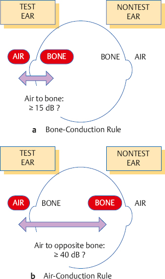
Fig. 9.6 When to retest with masking for bone- and air-conduction when using standard audiometric (supra-aural) earphones. (a) The bone-conduction masking rule asks whether the air-bone-gap is ≥ 15 dB (i.e., > 10 dB) within the test ear. (b) The air-conduction masking rule asks whether there is a difference of ≥ 40 dB between the air-conduction threshold on the test side and the bone-conduction thresholds on the nontest side.
When to Mask for Air-Conduction
Recall that we must use masking whenever cross-hearing might occur. Cross-hearing for an air-conduction signal occurs via the bone-conduction route, and depends on three parameters: (1) the sound level in dB HL presented to the TE; (2) the amount of IA in dB, which determines how much of the signal crosses over; and (3) the true bone-conduction threshold in dB HL of the NTE, which determines whether this signal is audible in the NTE.
Consequently, one must mask for air-conduction whenever the sound (in dB HL) being presented to the TE is able to reach the bone-conduction threshold (in dB HL) of the NTE. Because we need to know the NTE’s real bone-conduction thresholds, we must mask for bone-conduction before masking for air-conduction. This also means that the unmasked airand bone-conduction thresholds should be obtained before any masking is accomplished.
The rule for when to mask for air-conduction is shown in Fig. 9.6b and may be stated in several ways. Using the minimum IA value of 40 dB as our criterion, masking for AC is needed whenever the test ear’s air-conduction threshold (ACT) and the nontest ear’s bone-conduction threshold (BCN) differ by 40 dB or more. Some audiologists call the spread between ACT and BCN an air-opposite-bone-gap (AOBG) or an air-contralateral-bone-gap (ACBG). Using this terminology, masking is necessary whenever the following relationship applies:
AOBG ≥ 40 dB.
For the mathematically minded, it is necessary to retest an air-conduction threshold with masking whenever:
(ACT − BCN ≥ 40 dB
Of course, this comparison is done individually for each test frequency (usually between 250 and 4000 Hz), and one compares the two ears at the same frequency. (One should remember that the 40 dB figure being used here and elsewhere assumes that standard, supra-aural audiometric earphones are being used. It should be replaced with the appropriate minimum IA value (Fig. 9.5) when testing with insert earphones.)
The rule just described is really simpler than it might seem. Suppose the right air-conduction threshold is 50 dB HL and the left bone-conduction threshold is 5 dB HL (at the same frequency, of course). Are they at least 40 dB apart? The answer is yes (50 – 5 = 45, and 45 dB is certainly ≥ 40 dB). Therefore, the right air-conduction threshold must be retested with masking noise in the left ear. In a second example, the right air-conduction threshold is 50 dB HL and the left bone-conduction threshold is 15 dB HL. Are they at least 40 dB apart? The answer is no (50 – 15 = 35, and 35 dB is less than the 40 dB criterion). Therefore, the right ear’s air-conduction threshold does not need to be retested with masking noise in the left ear. In other words, the right ear’s original air-conduction threshold of 50 dB HL is considered to be its true threshold. Consider one more example, in which the right ear’s air-conduction threshold is 75 dB HL and the left ear’s bone-conduction threshold is 35 dB HL. The right ear needs to be retested with masking because the AOBG is 40 dB, which meets the ≥ 40 dB criterion. It must be emphasized that the comparison made in the air-conduction masking decision is always between air-conduction on the test side and bone-conduction on the nontest side, because this is the crossover route. It cannot validly be based on a comparison between the air-conduction thresholds of the two ears. A logical exception occurs when the air-conduction threshold of the NTE is better than its bone-conduction threshold at the same frequency—for example, when the air-conduction threshold is 10 dB HL and the bone-conduction threshold is 20 dB HL. Here, one uses the better air-conduction threshold (10 dB HL in this example).
Central Masking
As a scientific phenomenon, masking means a threshold shift for a signal that occurs when the noise and signal are presented to the same ear. Very technically, this is called “direct, ipsilateral masking,” and it occurs because the noise and signal are present within the same cochlea. In clinical masking we are trying to cause direct, ipsilateral masking of the non test ear so that we can be sure that only the test ear is actually hearing the test signal.
Central masking can occur when the signal and noise are presented to different ears. Suppose that the right ear gets the tone and the left ear gets the noise. Let us also assume that we know for a fact that there is no crossover for either the signal or the noise. (We know this because both the tone and the noise levels being used are well below interaural attenuation.) Clearly, direct ipsilateral masking cannot occur because the signal is in one cochlea and the noise is in the other cochlea. We find that the right ear’s threshold is consistently shifted (from, say, 5 dB HL to 10 dB HL) whenever there is noise in the left ear. The reason a noise in one ear can cause a threshold shift (masking) in the other ear is as follows. Even though the peripheral ears are physically separate, the neural signals that come from the two cochleae are combined in the central auditory nervous system (CANS). The noise in one ear can interfere with the ability to hear a tone in the other ear because they interact in the CANS.
Although central masking is a real phenomenon, it is not the effect of interest during clinical masking. In fact, central masking actually complicates matters in clinical masking. For this reason, the amount of central masking that occurs is of some importance when clinical masking is being done. Clinicians generally consider the central masking effect to be ~ 5 dB; however, threshold shifts as large as 15 dB have been reported (Liden, Nilsson, & Anderson 1959b), and the effect increases with the magnitude of the masking noise (Studebaker 1962; Dirks 1964; Dirks & Malmquist 1964). More information about the nature and parameters of central masking may be found in Gelfand (2010). We will follow the conservative practice of allowing for 5 dB of central masking during clinical masking procedures.
Effective Masking Calibration
If the audiometer is set up to produce a 1000 Hz pure tone, then an attenuator dial reading of 50 means that a 1000 Hz tone will be presented to the patient at 50 dB HL. If the patient can hear this, then we know her 1000 Hz tonal threshold is 50 dB HL or less. If we change the input selector from “tone” to “NBN,” then many audiometers will produce a 1000 Hz NBN at 50 dB HL. This means a narrow band of noise is centered around 1000 Hz, which has an overall level equal to that of a 1000 Hz tone at 50 dB HL. If the patient can hear this, then we know her 1000 Hz NBN threshold is 50 dB HL or less.
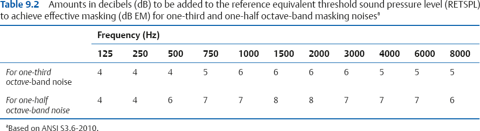
However, what if we want to use the noise to mask a 50 dB HL 1000 Hz tone? To meet this goal, the level of a NBN noise would have to be increased. The ANSI audiometer standard (ANSI S3.6-2010) provides corrections to be built in to the audiometer’s masking channel, so that the masking level dial is calibrated in decibels of effective masking (dB EM). These corrections are shown in Table 9.2. However, it is up to the clinician to verify that these dial readings actually provide effective masking on her own equipment, and if necessary to determine the proper masking noise settings. Specifically, she must determine the difference in decibels between the level of a given tone and the level of the noise that just masks that tone. This difference is often called the effective masking level (EML), but is more readily understood if it is called the minimum effective masking correction (MEMC) because it is the correction that must be added to the tone’s level to arrive at a minimum noise level that will effectively mask that tone. For example, suppose it takes 55 dB HL of NBN to just mask a 50 dB HL tone. This means that to mask a tone, the noise has to be 5 dB higher than the tone; that is, the MEMC in this case is 55 dB – 50 dB = 5 dB.
The clinician arrives at a set of MEMCs for each audiometer by performing a simple biological (psychoacoustic) calibration study using normal-hearing subjects. There are various approaches, but the one about to be outlined is probably the simplest. The audiometer must have two channels. One channel will produce the tone, and the second channel will produce the masking noise. The output selector is set up so that both channels are directed into the same earphone, that is, both the tone and the noise are directed into the same ear because we want to find out how much noise is needed to mask the tone. Most audiometers automatically set the tone and the NBN to the same frequency. If the audiometer has separate frequency controls for the two channels, then they should both be set to the same frequency (after all, we do not want to use a 4000 Hz NBN to mask a 1000 Hz tone).
We will go through the basic sequence at 1000 Hz. The noise attenuator is turned to a comfortable level, such as 40 dB HL, and the noise is set to the constantly on position. We now have a continuous 1000 Hz narrow-band noise at 40 dB HL. Next, we find the tone’s threshold against the background of the continuously on noise. Many clinicians use a pulsing tone for this purpose because it makes the listening task somewhat easier. Having found the threshold for the tone (where it is just audible over the noise), the tone is then decreased in 5 dB steps until it is just inaudible. This is where the tone is just masked by the noise. Suppose we find that the tone’s level is 35 dB HL at this point. We can now say that a 1000 Hz NBN at 40 dB will just mask a 35 dB 1000 Hz tone, or that a 35 dB tone is just masked by a 40 dB noise at 1000 Hz. Either way, the noise has to be 5 dB higher than the tone to just mask it in this example. This strategy is repeated several times to arrive at an average value, which represents that subject’s MEMC at 1000 Hz. The procedure is then repeated at the remaining frequencies.
This type of procedure can also be used to arrive at minimal effective masking levels on an individual patient basis (Veniar 1965). Veniar’s method involves presenting the tone at a constant level and increasing the noise (in the same earphone) until the patient no longer hears the tone. The student should also be aware that physical masking noise calibration methods based on electroacoustic measurements and/or calculations are also available (e.g., Sanders 1972; Townsend & Schwartz 1976), although most clinicians are probably best served by the psychoacoustic approach.
Some audiometers, such as portable instruments and those mainly intended for screening purposes, do not allow one to direct the tone and noise into the same channel. In this case, a simple mixing circuit must be built to properly combine the noise and tone in the same earphone (see Studebaker 1967, p. 362). Fortunately, this is rarely necessary in modern practice.
The Initial Masking Level
Once we have decided to retest the TE with masking noise in the NTE, we must decide how much masking noise to use. The recommended approach is the initial masking level method described by Martin (1967, 1974, 1980). Other formulas have also been proposed (Liden, Nilsson, & Anderson 1959b; Studebaker 1964). However, they are more complex and have been shown to yield similar masking levels to the recommended approach (Martin 1974). Obviously, we must start with enough noise to render the test tone inaudible in the NTE. It is important to remember at this juncture that we already have an unmasked threshold; we are just not sure about which ear is hearing it. If the threshold is really coming from the NTE, then we must start with enough noise to mask the NTE at threshold.
Initial Masking Level for Air-Conduction
We will assume that we have previously determined the average minimum effective masking correction for our audiometer to be 5 dB higher than the hearing level of the test tone at every frequency. In other words, the masking noise level must be 5 dB higher than the tone level. For example, the noise level would have to be set to 15 dB HL to mask a 10 dB HL tone, or 60 dB HL to mask a 55 dB HL tone. We must also add a 10 dB safety factor because the MEMC is an average. Adding a 10 dB safety factor means that our starting masking level will have an attenuator (dB HL) dial reading that is 15 dB higher than the unmasked threshold in the NTE. For example, if the NTE’s air-conduction threshold is 20 dB HL, then the initial masking level will be:
20 dB HL | (AC threshold of the tone we want to mask) |
+ 5 dB | (MEM correction) |
= 25 dB HL | (Average MEM level for a 20 dB HL tone) |
+ 10 dB | (Safety factor) |
= 35 dB HL | (Initial Masking Level) |
In other words, if the air-conduction threshold of the NTE is 20 dB HL, we will use 35 dB HL of masking noise as the starting masking level. This value is the initial masking level (IML). For the mathematically oriented, the initial masking level (in dB HL) directed into the NTE may be reduced to the formula
IML = HLN + MEMC + SF
where HLN is the air-conduction threshold hearing level of the NTE, MEMC is the minimum effective masking correction, and SF is the safety factor.
Initial Masking Level for Bone-Conduction and the Occlusion Effect
The IML for bone-conduction testing is similar to the one used for air-conduction with the important addition of a factor to account for the occlusion effect (OE). This is done because the earphone covering the NTE can introduce an occlusion effect, which is an increase in the level of a bone-conduction signal due to occluding the ear canal.
A simple example will show how the OE affects a masked bone-conduction threshold. Suppose an unmasked bone-conduction threshold is 35 dB HL, and the test ear needs to be retested with masking. (To keep things simple, the NTE has a 35 dB HL sensorineural loss.) The 35 dB HL bone-conduction threshold was obtained without any earphones covering the ear canals, and is thus an unoccluded bone-conduction threshold. Here the NTE receives the tone at 35 dB HL (at the cochlea). When we retest this bone-conduction with masking, the NTE is covered with the earphone used to deliver the masking noise. In so doing, we change the bone-conduction test from unoccluded to occluded, which may cause an occlusion effect to occur. Let us assume that the OE is 15 dB. This means that a 35 dB HL bone-conduction signal from the audiometer will be boosted by 15 dB to 50 dB HL at the cochlea of the NTE. Consider what this means from the standpoint of the IML. If we use the above IML formula intended for air-conduction testing, we would be unsuccessfully trying to mask what is really a 50 dB HL signal with a noise that can only mask a tone as high as 35 dB HL. In other words, since occluding the NTE effectively boosted the tone level by 15 dB, we would also need to increase the amount of masking noise by 15 dB in order to account for the occlusion effect, as follows:
35 dB HL | (AC threshold of the tone we want to mask) |
+ 5 dB | (MEM correction) |
= 40 dB HL | (Average MEM level for a 35 dB HL tone) |
+ 10 dB | (Safety factor) |
= 50 dB HL | (IML, unoccluded) |
+ 15 dB | (Correction for the OE) |
= 65 dB HL | (Initial masking level accounting for the OE) |
The initial masking level formula for bone-conduction testing accounts for the OE, and may be written as
IML + HLN + MEMC + SF + OE
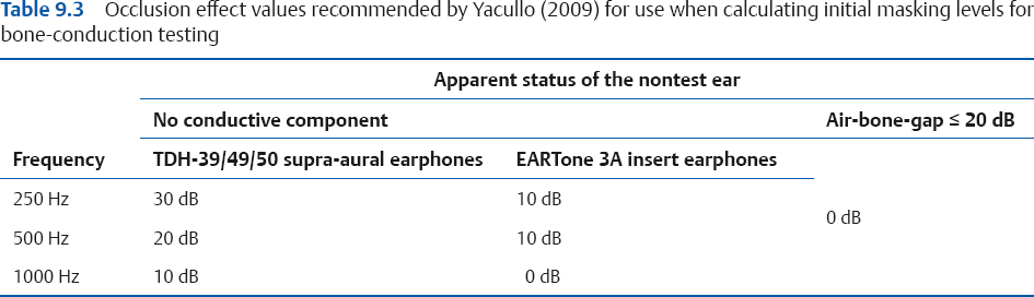
Determining the Occlusion Effect
We need to know the size of the OE to determine the IML. One approach is to use fixed OE values (e.g., Studebaker 1979; Goldstein & Newman 1985; Yacullo 2009), such as the ones shown in Table 9.3. The alternative approach, which is recommended here, is that clinicians should determine the presence and magnitude of the OE on an individual patient basis. The reason is that we cannot assume any predetermined value because the occlusion effect (1) differs with frequency, (2) is highly variable among people, and (3) is absent when there is a conductive pathology. Consequently, we must first perform an easy but important test to determine the presence and size of the OE before determining IMLs for bone-conduction.
The recommended procedure employs the audiometric Bing test (Martin, Butler, & Burns 1974), and is as follows: Having already obtained the unmasked bone-conduction thresholds, the audiologist places the earphone over the NTE and retests the bone-conduction without any noise. An OE is considered to be present if the occluded threshold is better (lower) than the unoccluded one; the size of the OE is simply the difference between them. In the case of the above example, the unoccluded bone-conduction threshold would be 35 dB and the occluded bone-conduction threshold would be 20 dB HL, revealing that the OE is 35 – 20 = 15 dB. The resulting OE value is then used in the calculation of the IML. The bone-conduction IML formula is the same as the air-conduction formula when the OE is zero. This is done for each frequency up to and including 1000 Hz, which is the region where OEs are expected to occur.
This procedure works because the OE increases the level of signal reaching the cochlea, so the dial reading of the threshold is lowered by the amount of the OE (which was 15 dB in our example).
There are at least two supplemental benefits of the audiometric Bing test. First, it provides supportive diagnostic information because the OE tends to be present in ears that are normal or have sensorineural impairments, and tends to be absent in ears with conductive or mixed losses. Second, the clinician can be alerted to the inadvertent displacement of the bone-conduction vibration by occluded thresholds that are poorer (higher) than the unoccluded thresholds.
Using the Initial Masking Level
Once we have determined that masking is necessary, the first step is to retest the threshold in question while masking noise is being presented to the NTE at the IML.
After instructing the patient and setting up the equipment for masked testing (see below), the masking noise is turned on. With the IML in the NTE, we now retest the threshold for the TE. As previously mentioned, we will allow for 5 dB of central masking during clinical masking procedures. If the patient responds within 5 dB of the same level obtained previously without masking, then we consider the original threshold to be confirmed as being derived from the test ear. This is so because the patient can still hear the tone even though the NTE is being masked; if the NTE is not hearing the tone, then it must have been heard in the TE. For example, suppose that the right ear’s unmasked threshold was 40 dB HL. This threshold is considered to be true if it stays at 40 dB HL (or shifts only 5 dB to 45 dB HL) with the initial masking level in the left (nontest) ear. The 40 dB HL is now called a masked threshold, and the masking procedure is finished for this tone.
The alternative outcome is that the IML causes the threshold to shift by more than 5 dB from its original, unmasked value. For example, the right ear’s unmasked threshold of 40 dB HL might shift to 50 dB HL with the IML in the left ear. In this case, even though the tone was directed into the right ear, the original (unmasked) threshold must have come from the left (nontest) ear. Why? Because if the tone was really heard in the right ear, then putting noise into the left would not have changed anything—it would still be heard in the right ear. If appropriate masking noise in the left ear stops the patient from hearing a tone from the right earphone, then the original threshold must have been originally picked up in the left ear via cross-hearing. Under these circumstances we must now move to the next phase of the masking procedure, which involves finding the actual threshold of the test ear using the threshold shift or plateau method.
We may summarize the use of the initial masking level as follows: (1) The original threshold is confirmed if it stays the same (within 5 dB) at the initial masking level. (2) An unmasked threshold was probably heard in the non-test ear if the initial masking level causes it to shift more than 5 dB.
The Plateau Method
The plateau method is a widely accepted strategy for finding the true masked threshold of the TE and was described by Hood (1960). (A more efficient approach that can be used if the unmasked air-conduction thresholds differ by ≥ 25 dB between the ears is described later in the chapter.) Sometimes called the threshold shift method, the logic of the plateau strategy can be understood in terms of Fig. 9.7, which shows the results of a hypothetical test. The ordinate represents the threshold of the tone in the test ear when it is presented alone (unmasked) and when various levels of masking noise are being presented to the NTE. The abscissa shows the level of the masking noise in the NTE, as well as the unmasked (unm) situation. In this example, the apparent threshold of the test tone is 50 dB HL, indicated by the symbol for the unmasked (unm) situation. This is not the actual threshold of the TE because the lowest masking level used (20 dB) caused it to shift to 60 dB HL. Notice that the rest of the graph breaks down into three distinct ranges, labeled undermasking, plateau, and overmasking.
Undermasking
When a tone is really being heard by the nontest ear via cross-hearing, then raising the level of the masking noise will cause the masked threshold to increase. This occurs because the noise and tone are both in the same (nontest) ear. For example, Fig. 9.7 shows that raising the masking noise from 20 to 35 dB HL caused the apparent tonal threshold to rise from 60 to 75 dB HL. The one-for-one elevation occurs because masking increases linearly with masker level, as we learned in Chapter 3. This linear increase of apparent threshold with masking noise level indicates that the tone is still being picked up by the NTE. We call this undermasking because the amount of noise is not sufficient to exclude the NTE from the test. Thus, undermasking occurs when there is not enough masking noise, so that the tone is being heard by the nontest ear, as in Fig. 9.8a.
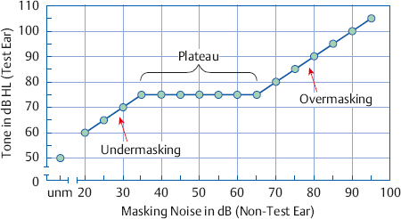
Fig. 9.7 The masking plateau (see text). Abbreviation: unm, unmasked. In this example, the unmasked threshold of the test tone is 50 dB HL, and its masked threshold is 75 dB HL.
Stay updated, free articles. Join our Telegram channel

Full access? Get Clinical Tree


