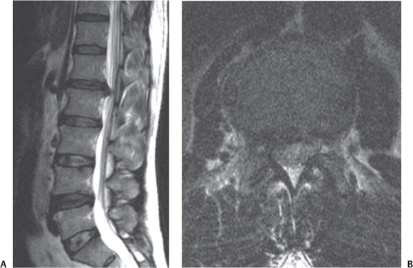
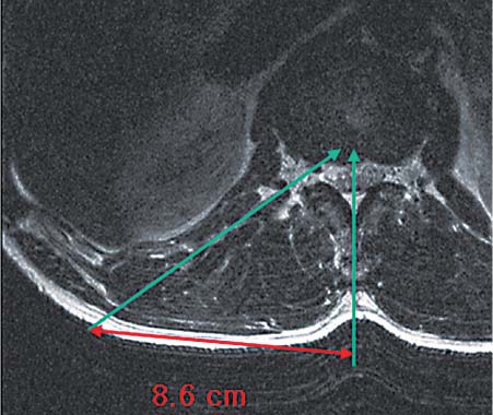
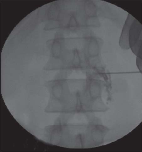
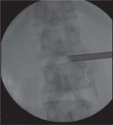
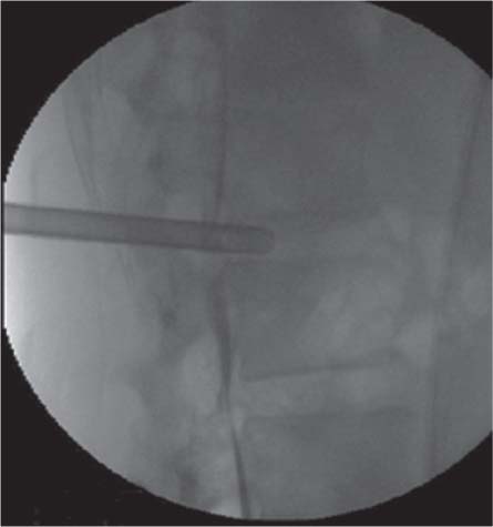
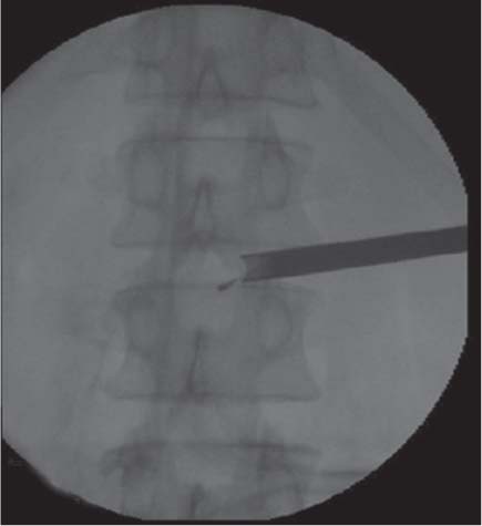
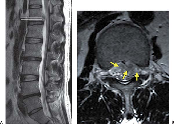
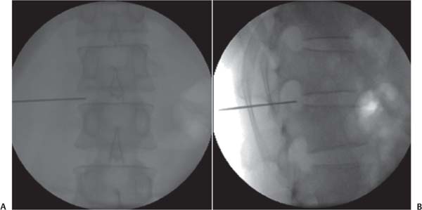
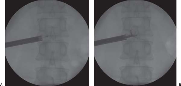
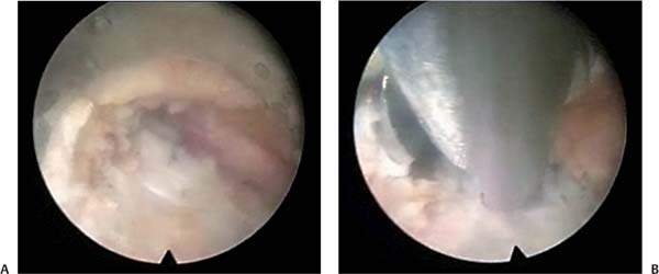
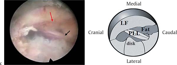
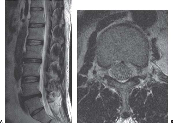
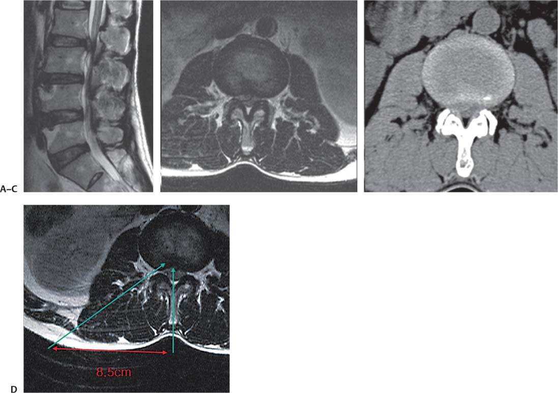
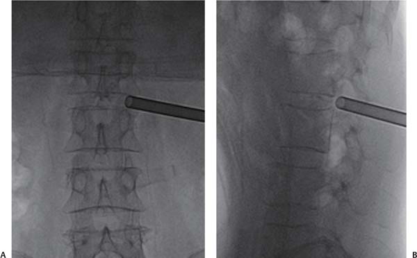
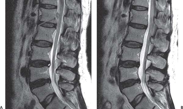
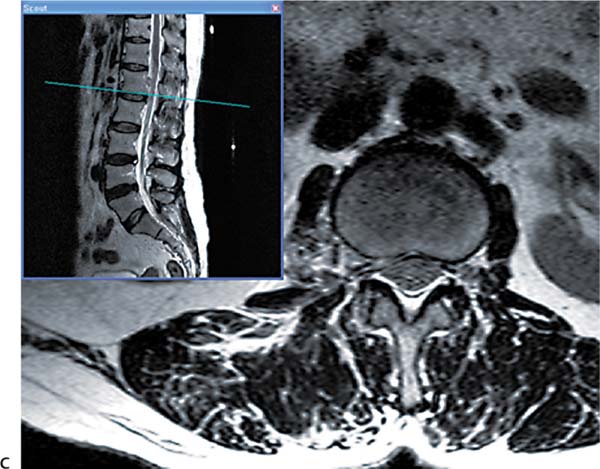
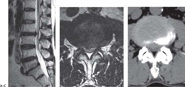
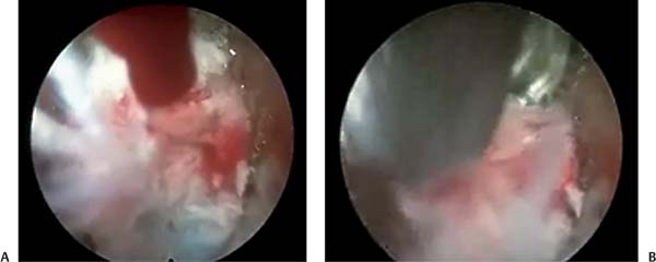
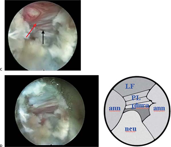
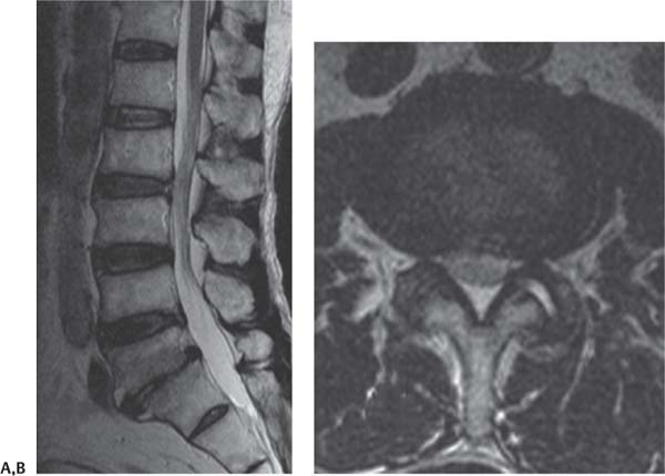
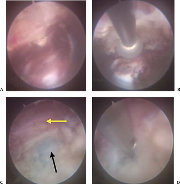
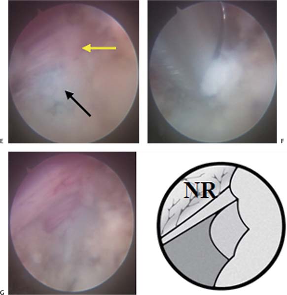
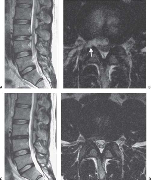
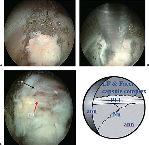
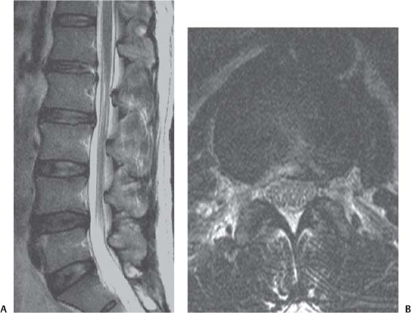
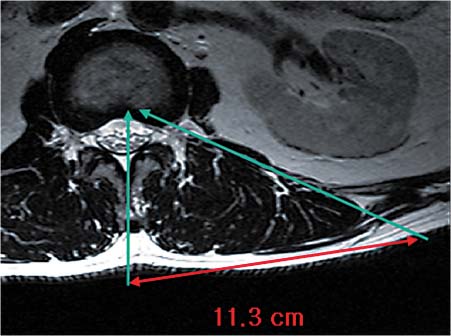
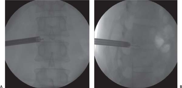
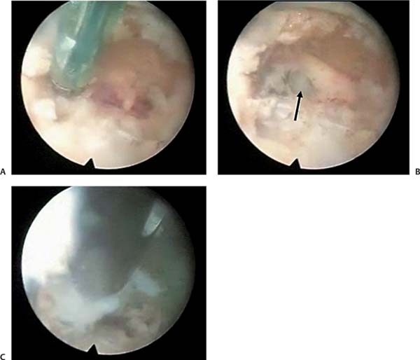
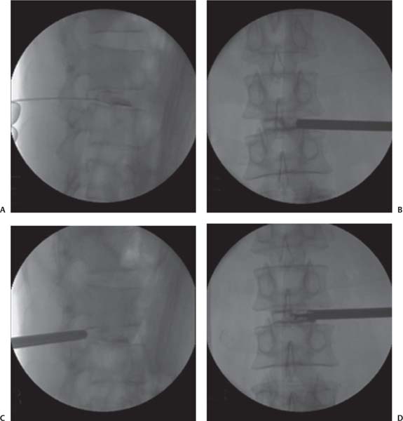
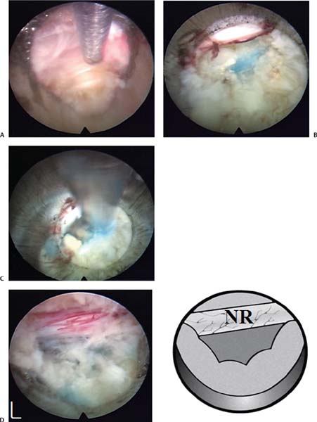
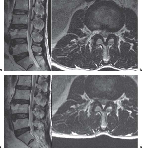
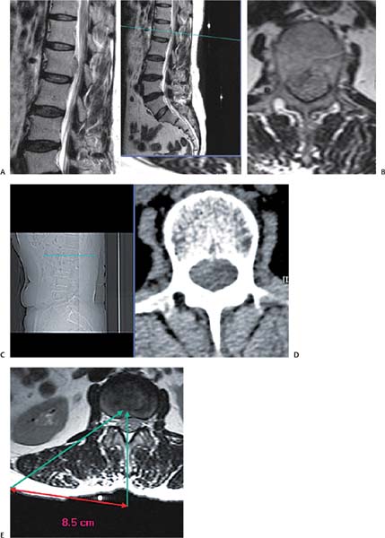
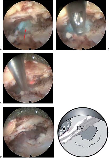
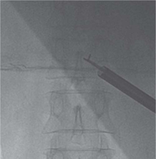
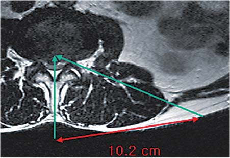
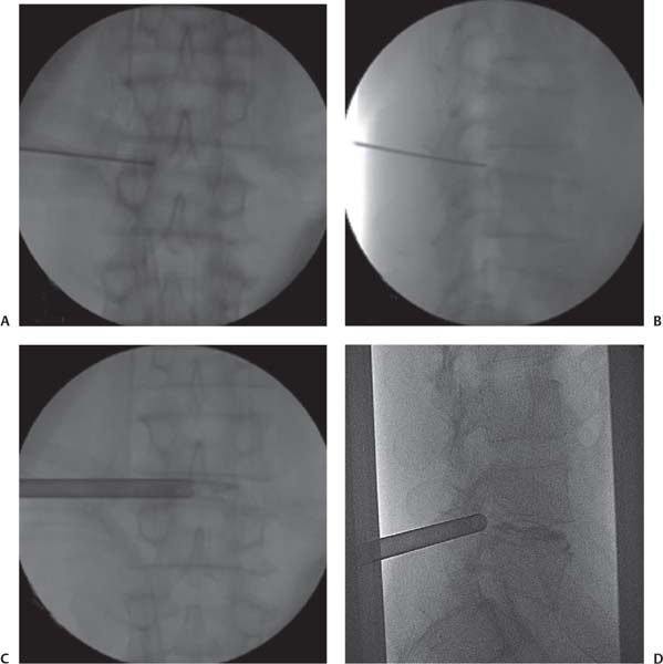
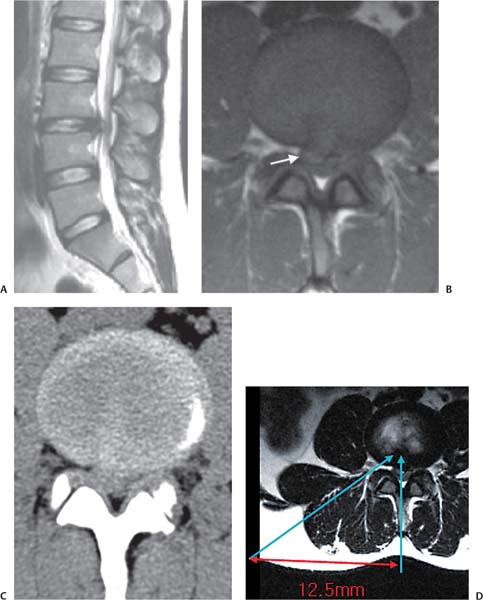
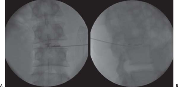
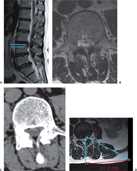
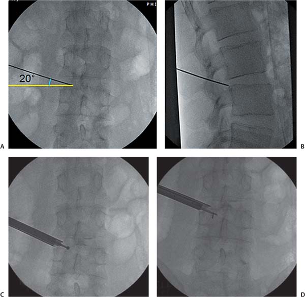
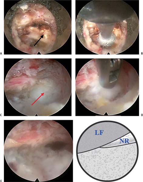
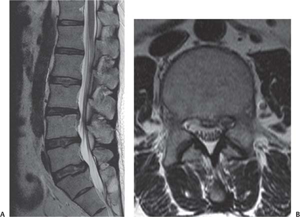
18 Case Presentations and Surgical Technique: Percutaneous Endoscopic Lumbar Diskectomy • A 54-year-old man presented with right buttock and leg pain and weakness of the right quadriceps. • A femoral stretch test was positive. • The diagnostic imaging included magnetic resonance imaging (MRI) and computed tomographic (CT) scans. • MRI showed a slightly downward-migrated disk herniation at the L1-L2 level compressing the thecal sac and traversing nerve root (TNR) (Fig. 18.1). • The CT scan showed a soft disk herniation at the L1-L2 level (Fig. 18.2). • The lines for measurement guidance are drawn as described in chapter 15. At upper levels, the angle of the intended needle trajectory line is relatively steep and the annular puncture site is also kept at the midpedicular level to increase the margin of safety. • The skin entry point should lie closer to the midline (8.6 cm in this case) for an upper lumbar disk herniation than for a lower lumbar herniation (12 to 14 cm) (Fig. 18.3). 1. A radiculogram is performed before penetrating the annulus to highlight the path of the nerve root. The tip of the needle is placed at the midpedicular line (Fig. 18.4). 2. The tip of the working cannula is placed midway between the pedicle and the spinous process in the anteroposterior (AP) view (Fig. 18.5). At the same location, the cannula lies in the posterior annulus and nucleus pulposus (Fig. 18.6). Note the difference in the cannula tip’s position from that for the lower lumbar levels, where the cannula tip is kept only in the posterior annulus. After removal of the fragments, one can check for the free course of the nerve root with the flexible bipolar probe (Fig. 18.7). Fig. 18.1 Preoperative sagittal (A) and axial (B) MRIs showing a slightly downward-migrated disk herniation at L1-L2. Fig. 18.2 Preoperative CT scan showing a soft disk herniation at L1-L2. Fig. 18.3 The skin entry point is 8.6 cm from the midline (arrows). Fig. 18.4 Needle placement for the radiculogram. The tip of the needle can be seen at the midpedicular line. • On introduction of the endoscope, the base of the blue-stained herniated disk tissue is visualized (Fig. 18.8A) • Some of the disk tissue is removed with the forceps to create a working space (Fig. 18.8B). This procedure is particularly needed when treating the upper lumbar levels. Because the working cannula is usually kept a little further ahead than the lower lumbar levels, the removal of some disk tissue from the posterior half is needed to visualize the herniated fragment. In the lower lumbar levels, the base of the herniated disk and torn annulus can be accessed without sacrificing much of the disk tissue. Fig. 18.5 AP fluoroscopic view of the placement of the working cannula. The cannula is seen appropriately placed midway between the pedicle and the spinous process. Fig. 18.6 Lateral fluoroscopic view of the working cannula placement. The cannula can be seen in the posterior annulus and nucleus pulposus. • The fibers of the posterior longitudinal ligament (PLL) and some strands of epidural fat tissue are seen after removal of the herniated mass (Fig. 18.8C). At the upper lumbar levels, it is not mandatory to visualize the nerve root due to the high risk of neural injury while attempting that step. Instead, the adequacy of decompression can be checked indirectly by free movement of the PLL on coughing and probing with the flexible radiofrequency probe. Fig. 18.7 AP fluoroscopic view showing the flexible bipolar probe being used to check for the free course of the nerve root after removal of the fragments. • The postoperative sagittal MRI showed complete removal of the herniated nuclear contents from the spinal canal (Fig. 18.9A). The presence of the cerebrospinal fluid (CSF) column anterior to the thecal sac can be seen on MRI. • The postoperative axial MRI showed the expanded thecal sac (Fig. 18.9B). • Final needle positioning must be at the midpedicular line on the AP view and posterior body line on the lateral view. • Check the patient’s motor power frequently by having feedback from his response. • Don’t use heat-producing equipment (laser, excessive radiofrequency in the upper lumbar levels) because neural tissue is compactly packed in the thecal sac with little CSF cushion and less buffer effect. Fig. 18.8 Intraoperative endoscopic views. (A) As the endoscope is introduced, the base of the blue-stained herniated disk tissue can be seen. (B) Some of the disk tissue is then removed with forceps. (C) Endoscopic view and corresponding illustration of fibers of the posterior longitudinal ligament (PLL). Some epidural fat tissue can be seen after removal of the herniated mass. ann, annulus; LF, ligamentum flavum; Nu, nucleus pulposus. • A 43-year-old man presented with left leg pain that was scored at 5/10 and back pain that was scored at 7/10 on the visual analog scale (VAS). • The patient’s chief complaint is left flank and buttock pain. • Preoperative imaging shows a left paramedian extrusion of a ruptured disk with upward migration at the L1-L2 level (Fig. 18.10). • The skin entry point is ~11 cm from midline (Fig. 18.11). • Parallel or mild caudal to cranial angulation of trajectory is needed. 1. The angle of needle insertion is parallel to the upper end plate of the lower vertebral body, and the tip of the needle is positioned at the midpedicular line (Fig. 18.12). 2. After sequential dilators, the working channel is inserted (Fig. 18.13). Fig. 18.9 (A) Postoperative sagittal MRI showing complete removal of the herniated nuclear contents from the spinal canal. The cerebrospinal fluid column can be seen anterior to the thecal sac. (B) Postoperative axial MRI showing the expanded thecal sac. Fig. 18.10 Sagittal (A) and axial (B) MRIs show a left paramedian extrusion of a ruptured disk with upward migration at the L1-L2 level (arrows). Fig. 18.11 The skin entry point is ~11 cm from the midline (arrows). Fig. 18.12 The correct angle of the needle during insertion is shown in AP (A) and lateral (B) fluoroscopic views. Fig. 18.13 The placement of the working channel is shown in AP (A) and lateral (B) fluoroscopic views. 3. The upward-migrated disk fragment is removed after making a caudal to cranial angulation of the working channel (Fig. 18.14). • After inserting the working channel, the soft tissue is ablated with the radiofrequency probe (Fig. 18.15A). • After radiofrequency ablation, the annulus tear site and blue-stained disk material are seen (Fig. 18.15B). • The ruptured disk fragment is then removed (Fig. 18.15C). • The working channel is angled cranially to remove the migrated disk fragment (Fig. 18.16A). • The jaw of the pituitary rongeur is opened cranially to remove the upward-migrated disk (Fig. 18.16B). • After decompression, redundant remnant PLL and epidural fat can be identified. Finally, well restored dural pulsation must be confirmed (Fig. 18.16C). • The sagittal MRI showed removal of the disk fragment (Fig. 18.17A). Fig. 18.14 The correct angle of the working channel is shown (A) as well as the removal of the migrated disk fragment (B). Fig. 18.15 Intraoperative endoscopic views. (A) The working channel is inserted and the soft tissue ablated with the radiofrequency probe. (B) Afterward, the annulus tear site and blue-stained disk material can be seen (arrow). (C) Finally, the ruptured disk fragment is removed. Fig. 18.16 Intraoperative endoscopic views. (A) The view of the endoscope after angling the working channel cranially to expose the migrated disk fragment. (B) The pituitary rongeur is shown with the jaw open cranially to remove the upward-migrated disk. (C) The posterior longitudinal ligament (PLL) (black arrow) and epidural fat (red arrow) are seen. LF, ligamentum flavum. • The axial MRI showed removal of the extruded disk fragment and decompressed nerve root (Fig. 18.17B). • The needle must be inserted parallel to the upper end plate of the lower vertebral body. • Adequate diskography is important, but without too much injection of dye to avoid staining of the whole tissue. • It is not necessary to enter the disk space. Identify the axillary portion of the exiting root and follow this one cranially and medially until the blue-stained fragment is seen. Fig. 18.17 (A) Postoperative sagittal MRI showing removal of the disk fragment. (B) Postoperative axial MRI showing removal of the extruded disk fragment and decompression of the nerve root. • Remove the migrated loose fragment only. • Be certain there is complete removal of the disk fragment because there may sometimes be more than one. • Follow the same tips given for percutaneous endoscopic thoracic diskectomy (PETD). • A patient presented with right thigh pain and walking difficulty for 3 months. • Paresthesia on the right L3 dermatome was checked. • Sagittal and axial MRI and CT scan showed a central to right paramedian soft disk herniation at the L2-L3 level (Fig. 18.18). • For a herniated disk at the upper lumbar level, the target point is preferably kept at the midpedicular line or the lateral pedicular line to avoid neural injury because the dural sac lies more medially due to the narrow width of the pedicles at this level. • The skin entry point is selected by drawing various lines as shown in the axial MRI scan, and the distance from midline is ~8.5 cm (Fig. 18.18D) 1. Diskography is performed, and the epidural leakage of dye through annular fissure is observed, which implies the noncontained nature of the disk herniation (Fig. 18.19A). 2. Even though the annular puncture site is kept at the midpedicular line, the tip of the working cannula can be advanced further once it pierces the posterior annulus (Fig. 18.19B). 3. The working cannula is positioned within the posterior annulus (Fig. 18.19C). Fig. 18.18 Preoperative sagittal (A) and axial (B) MRIs and CT scan (C) showing a central to right paramedian soft disk herniation at the L2-L3 level. (D) Axial image for preoperative planning demonstrates the skin entry point at ~8.5 cm from the midline (arrows). Fig. 18.19 (A) Lateral fluoroscopic view during diskography showing epidural leakage of dye through the annular fissure. (B) AP view showing the working cannula piercing the posterior annulus. (C) Lateral view showing the working cannula’s position within the posterior annulus. (D) AP view showing the proper position of the grasping forceps. 4. The proper position of the grasping forceps is checked frequently with the fluoroscope to avoid damage to the contralateral nerve root (Fig. 18.19D). • Annular release is achieved using the side-firing holmium: yttrium-aluminum-garnet (Ho:YAG) laser (Fig. 18.20A). • After the annular release, the annular fissure is widened and the base of the blue-stained herniated nucleus pulposus (HNP) fragment is observed. Part of the ligamentum flavum (LF) covering the medial aspect of the facet joint is also seen (Fig. 18.20B). • The herniated disk fragment is then grabbed and removed with endoscopic forceps (Fig. 18.20C). • After complete removal of the herniated fragment, the TNR is free and well decompressed (Fig. 18.20D). • Immediate postoperative sagittal and axial MRI showed complete removal of the HNP and well decompressed neural tissues (Fig. 18.21A,B). Fig. 18.20 Endoscopic findings (12 o’clock is dorsal, 3 o’clock is cranial, 6 o’clock is ventral, and 9 o’clock is caudal). (A) Intraoperative endoscopic view showing annular release using the side-firing Ho:YAG laser. Note the pale yellow fibers of the annulus (from center toward 6 o’clock position), which is cut by the laser. (B) The annular fissure is widened and the base of the blue-stained herniated nucleus pulposus fragment is observed. Part of the ligamentum flavum is also seen. (C) The endoscopic forceps are seen removing the herniated disk fragment. (D) Final view and illustration showing the decompressed traversing nerve root (NR). Fig. 18.21 Postoperative sagittal (A) and axial (B) MRIs showing complete removal of the herniated nucleus pulposus and decompressed neural tissues. The remaining annular flap is also noted. Follow-up sagittal (C) and axial (D) MRIs showing the healed annular flap. • At 2-month follow-up, sagittal and axial MRI showed that the annular flap was healed. (Fig. 18.21C,D). • A patient was presented with right inguinal and gluteal pain for 2 weeks. • Weakness of the right hip flexors and hypoesthesia at the right L2 dermatome were observed. • The sagittal MRI scan showed an L2-L3 disk herniation that was migrated upward (Fig. 18.22A,B) and the axial MRI and CT scan with topogram also showed the soft migrated fragment lying beside the pedicle of the L2 vertebra (Fig. 18.22C,D). • For migrated disk herniations, the skin entry point is usually chosen from an opposite direction (i.e., for an upward-migrated disk herniation), making the skin entry point a little inferior than usual is preferred. This helps in easy manipulation of the working cannula while removing the migrated fragments. • AP and lateral view x-rays showed the intended trajectory of the working cannula (caudal to cranial angle of ~10 degrees). • Skin entry point is ~8.5 cm from the midline and make caudal to cranial direction (Fig. 18.22E). Fig. 18.22 (A,B) Preoperative sagittal MRIs showing an L2-L3 disk herniation migrated upward. Preoperative axial MRI (C) and CT scan (D) with topogram show the soft migrated fragment lying beside the pedicle of the L2 vertebra. (E) Axial MRI demonstrating the determination of the proper skin entry point (arrows) in this case. • A slightly upward angle is needed for the working cannula. The tip of the working cannula is anchored over the annulus but does not pierce the disk space. From this location, the cannula can be further shifted up using a levering technique to remove the upward-migrated disk fragments (Fig. 18.23). • A part of the blue-stained herniated fragment is observed (Fig. 18.24A). • The herniated fragment is removed from the epidural space with the endoscopic forceps (Fig. 18.24B, Fig. 18.25). • Side-firing laser is used to remove the LF and annular covering of the HNP within the epidural space to mobilize the herniated fragment (Fig. 18.24C). • The herniated disk mass is removed (Fig. 18.24D). • Postoperative MRI showed the decompression of the HNP, but there was still a small sequestrated disk fragment (red arrow) (Fig. 18.26A). • MRI at 1-month follow-up showed regression of the remaining disk fragment (Fig. 18.26B,C). • Because of the upward migration of the disk fragment, the skin entry point must be placed more caudally than usual, so that caudal-cranial angulations can be done. • To stain the herniated disk blue, injection of indigo carmine mixed with dye is needed under continuous fluoroscopy until epidural leakage is noted. After this, infiltration should be stopped because unnecessary neural tissue may be stained. • A patient presented with left lateral thigh and leg pain for 3 weeks. • VAS was 9/10 for left leg pain and 3 to 4/10 for back pain. • Sagittal and axial MRI and CT scan showed a soft central disk herniation at the L2-L3 level (Fig. 18.27). • The skin entry point is selected by drawing various lines as shown in the axial MRI scan, and the distance from midline is ~10 cm (Fig. 18.28). This point is more lateral from the midline than in the case of a paramedian disk herniation of L2-L3. Fig. 18.23 AP (A) and lateral (B) fluoroscopic views of the correct positioning of the working cannula. Fig. 18.24 Intraoperative endoscopic views (12 o’clock is dorsal, 3 o’clock is cranial, 6 o’clock is ventral, 9 o’clock is caudal). (A) The blue-stained herniated fragment (arrow) can be seen on introduction of the endoscope. (B) The endoscopic forceps can be seen as the herniated fragment is removed. (C) The ligamentum flavum and annular covering of the herniated nucleus pulposus are removed with the laser. (D) Endoscopic view and illustration after the herniated disk mass is removed. EV, epidural vein. Fig. 18.25 Fluoroscopic view of the endoscopic forceps as the herniated fragment is removed. Fig. 18.26 (A) Postoperative sagittal MRI showing decompression of the herniated nucleus pulposus. A small remaining sequestrated disk fragment (red arrow) is visible. Imaging after 1 month of follow-up shows regression of the remaining disk fragment on sagittal (B) and axial (C) MRIs. Fig. 18.27 Preoperative sagittal (A) and axial (B) MRIs and axial CT (C) showing a soft central disk herniation at L2-L3. Fig. 18.28 The determination of the skin entry point is shown as described in the text. In this case the entry point (arrows) is ~10 cm from the midline. 1. To reach the centrally located disk herniation, the needle trajectory is more parallel to the end plate, and the needle tip must reach the medial margin of the pedicle (Fig. 18.29A,B). 2. The working channel is located within the posterior annulus in the lateral view, but its end must reach the center in the AP view (Fig. 18.29C,D). • The blue-stained disk fragment is seen just after introducing the endoscope (Fig. 18.30A). • At first, the base of the herniated disk is removed. The jaw opening of the pituitary rongeur must be directed to the ventral side to prevent injury of neural structures (Fig. 18.30B). • The ventral dura and root are identified (Fig. 18.30C). • After complete removal of the herniated fragment, the free and well-decompressed TNR and dural pulsation are observed (Fig. 18.30D). • Immediate postoperative sagittal and axial MRI scans show complete removal of the HNP and decompression of the neural tissues (Fig. 18.31). • An approach from a far lateral entry point and a trajectory parallel to the disk space enables placement of the needle in the posterior disk margin. This maneuver also permits the contralateral side to be easily reached and decompressed. • A 31-year-old male presented with predominant right lower anterior thigh pain and low back pain having lasted for 2 months. • The patient exhibited weakness of the right quadriceps and diminished right knee jerk. • MRI sagittal view shows a herniated L3-L4 disk and a central to right paramedian ruptured disk fragment is seen on axial views. CT scan reveals a soft disk (Fig. 18.32A–C). 1. The hypertrophied anterior surface of the superior facet may interfere with adequate visualization and proper positioning of the working instruments; thus it is necessary to use an endoscopic drill to shave off the overhanging bone in this case. 2. The skin entry point is selected by drawing various lines as shown in the axial MRI, and the distance from midline is ~12.5 cm and 5 degrees cranial to caudal direction (Fig. 18.32D). • On the AP view, the needle tip is located at midline, whereas in the lateral view it is located on the posterior one fifth of the vertebral body (Fig. 18.33). • The facet joint capsule along with the superior facet blocks the endoscopic view (Fig. 18.34A). • The endoscopic drill is used to remove the overhanging facet bone for a better view (Fig. 18.34B). • After the bone has been drilled, a part of the herniated disk fragment along with LF and the drilled undersur-face of the facet can be observed (Fig. 18.34C). • The mobilized herniated fragment is seen (Fig. 18.34D). • On further advancement of the cannula, the blue-stained hernia fragment is now clearly visualized going into the epidural space through the fibers of the PLL (Fig. 18.34E). • After mobilization, the herniated disk fragment is removed with an endoscopic grasping forceps (Fig. 18.34F). • After complete removal of the blue-stained herniated nucleus, the decompressed TNR is seen from the 12 o’clock to 9 o’clock position (Fig. 18.34G). • The sagittal MRI taken immediately after the surgery showed complete removal of the herniated nucleus, but superior and inferior annular flaps remain (Fig. 18.35A). • The postoperative axial MRI showed the working path and the drilled anterior surface of the superior facet making adequate space for instrument insertion in the tight foramen (Fig. 18.35B). • Imaging was repeated 2 months after the operation and showed healing of the annular flaps and the working path (Fig. 18.35C,D). Fig. 18.29 AP (A) and lateral (B) fluoroscopic views demonstrating the proper position of the needle. AP (C) and lateral (D) fluoroscopic views demonstrating the proper position of the working channel. Fig. 18.30 Intraoperative endoscopic findings (12 o’clock is dorsal, 3 o’clock is caudal, 6 o’clock is ventral, and 9 o’clock is cranial). (A) The blue-stained disk fragment can be seen on introduction of the endoscope. (B) The base of the herniated disk is removed with the pituitary rongeur. (C) The ventral dura (black arrow) and root (red arrow) can be identified. (D) The free and decompressed traversing nerve root is observed. ann, annulus; LF, ligamentum flavum; neu, nucleus pulposus; PL, posterior longitudinal ligament. Fig. 18.31 Postoperative sagittal (A) and axial (B) MRIs showing complete removal of the herniated nucleus pulposus and decompression of the neural tissues. Fig. 18.32 Preoperative imaging showing a herniated L3-L4 disk and a central to right paramedian ruptured disk fragment. (A) Sagittal MRI. (B) Axial MRI showing disk fragment (white arrow). (C) Axial CT scan. (D) Determination of the proper skin entry point (arrows). Fig. 18.33 AP (A) and lateral (B) fluoroscopic views of the proper needle placement. Fig. 18.34 Intraoperative endoscopic views (11 o’clock is dorsal, 2 o’clock is cranial, 5 o’clock is ventral, 8 o’clock is caudal). (A) The facet joint capsule and the superior facet block the initial endoscopic view. (B) The endoscopic drill is seen removing the overhanging facet bone for a better view. (C) Part of the herniated disk fragment (black arrow), the ligamentum flavum (yellow arrow), and the drilled undersurface of the facet are seen. (D) The mobilized herniated fragment is seen. (E) The blue-stained hernia fragment (black arrow) is now clearly visualized going into the epidural space through the fibers of the posterior longitudinal ligament (yellow arrow). (F) The endoscopic grasping forceps are seen removing the herniated disk fragment. (G) The decompressed traversing nerve root (NR) is seen from the 12 o’clock to the 9 o’clock position. • In this case with a hypertrophied facet, access to the posterior disk margin might require foraminoplasty (drilling the ventral surface of the superior facet). • During foraminoplasty, be aware of the patient’s neck pain complaint caused by probable intracranial or intrathecal pressure elevation. • Follow the general recommendations given for previous cases. • A 36-year-old man presented with left L4 dermatomal pain for 1 month. • The VAS result was left leg pain 9/10 and back pain 3 to 4/10. • The preoperative sagittal MRI showed a herniated disk at the L3-L4 level with downward migration. The axial view showed a left paramedian ruptured disk fragment, and a CT scan revealed a soft disk (Fig. 18.36A–C). Fig. 18.35 (A) Postoperative sagittal MRI showing complete removal of the herniated nucleus with remaining superior and inferior annular flaps. (B) Postoperative axial MRI showing the working path, including the drilled anterior surface of the superior facet (arrow). Follow-up sagittal (C) and axial (D) MRIs show healing of the annular flaps and the working path 2 months after surgery. • The skin entry point is selected by drawing various lines as shown in the axial MRI and the distance from midline is ~11.2 cm. The needle trajectory is directed 20 degrees cranial to caudal (Fig. 18.36D). 1. A slight downward angle of the needle is needed for an easier approach to the downward-migrated disk (Fig. 18.37A,B). 2. The ventral surface of the superior facet and the superomedial corner of the pedicle are drilled to prepare a path to the disk (Fig. 18.37C,D). Fig. 18.36 (A) Sagittal MRI showing a herniated disk at the L3-L4 level with downward migration. (B) Axial MRI showing the left paramedian ruptured disk fragment. (C) Axial CT scan reveals a soft disk. (D) The proper skin entry point calculation (arrows). Fig. 18.37 AP (A) and lateral (B) fluoroscopic views indicating proper needle placement. (C,D) The ventral surface of superior facet and superomedial corner of the pedicle is drilled to prepare the passage to reach the downward-migrated disk. • The endoscope is introduced and the initial view shows that the left superior margin of the L4 pedicle blocks the endoscope’s passage to the downward-migrated disk fragment (Fig. 18.38A). • The endoscopic drill is used to remove the superome-dial edge of the L4 pedicle for a better view and to gain working space (Fig. 18.38B). • After the pedicle has been drilled, a part of the herniated fragment and the LF can be seen (Fig. 18.38C). • The herniated disk fragment is then removed with endoscopic forceps (Fig. 18.38D). • After the fragment is removed, the epidural space can be visualized (Fig. 18.38E). • A postoperative sagittal MRI taken immediately after the operation showed the removal of the herniated nucleus but identified remaining superior and inferior annular flaps (Fig. 18.39A). • A postoperative axial MRI confirmed that the herniated fragment has been removed (Fig. 18.39B). • The needle trajectory in cases such as this must be in the craniocaudal direction. • Any patient complaints, especially leg discomfort and posterior neck pain, should be carefully noted during drilling. Careful monitoring for increased intracranial pressure is also needed. Fig. 18.38 Intraoperative endoscopic views (12 o’clock is dorsal, 9 o’clock is cranial, 6 o’clock is ventral, 3 o’clock is caudal). (A) The initial view with the endoscope showing the left superior margin of the L4 pedicle (arrow) blocking further passage of the endoscope. (B) The endoscopic drill can be seen as it is used to remove the superomedial edge of the L4 pedicle. (C) The herniated fragment (arrow) and the ligamentum flavum are now visible. (D) The endoscopic forceps are seen removing the herniated disk fragment. (E) After the herniated fragment is removed, the epidural space can be visualized. NR, nerve root. Fig. 18.39 Postoperative sagittal (A) and axial (B) MRIs showing the removal of the herniated nucleus but identifying remaining superior and inferior annular flaps. • A 54-year-old man presented with left anterior thigh pain and numbness lasting 1 month. • A grade IV weakness of the left quadriceps was identified. • Sagittal and axial MRI views were taken and identified a slightly upward-migrated disk herniation at the L3-L4 level, which was compressing the thecal sac and the exiting nerve root (Fig. 18.40A,B). • A CT scan also showed a soft disk herniation at the L3-L4 level (Fig. 18.40C,D). • The skin entry point is selected by drawing various lines as shown in the axial MRI (Fig. 18.41). • The distance from midline is ~12 cm. • The skin entry point is the same as the one used in cases of nonmigrated disk herniations, but its trajectory has a caudal to cranial angle. 1. Diskography is done after adequate needle positioning (Fig. 18.42).
Downward-Migrated Herniation at L1-L2
Clinical Findings
Preoperative Plan
Surgical Procedures
Endoscopic Findings
Results
Tips
Upward-Migrated Extrusion of the L1-L2 Disk
Clinical Findings
Preoperative Plan
Surgical Procedures
Endoscopic Findings
Results
Tips
Paramedian Extrusion at the L2-L3 Level
Clinical Findings
Preoperative Plan
Surgical Procedures
Endoscopic Findings
Results
Transforaminal L2-L3 Extrusion
Clinical Findings
Preoperative Plan
Surgical Procedures
Endoscopic Findings
Results
Tips
Central Transforaminal L2-L3 Protrusion
Clinical Findings
Preoperative Plan
Surgical Procedures
Endoscopic Findings
Results
Tips
Paramedian Extraforaminal L3-L4 Protrusion
Clinical Findings
Preoperative Planning
Surgical Procedures
Endoscopic Findings
Results
Tips
Downward-Migrated Herniation at the L3-L4 Level
Clinical Findings
Preoperative Plan
Surgical Procedures
Endoscopic Findings
Results
Tips
L3-L4 Level Upward-Migrated Foraminal Disk Herniation
Clinical Findings
Preoperative Plan
Surgical Procedures
Stay updated, free articles. Join our Telegram channel

Full access? Get Clinical Tree


