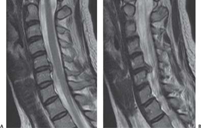
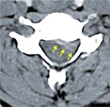
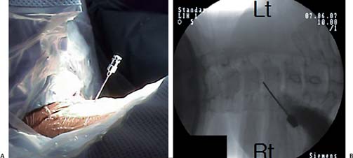
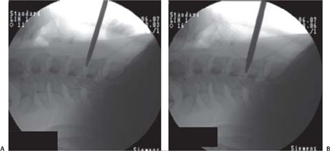
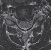
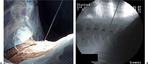
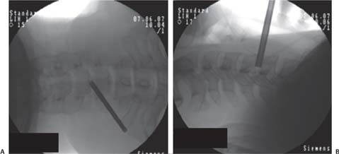
8 Case Presentations and Surgical Technique: Percutaneous Endoscopic Cervical Diskectomy • A 39-year-old female soprano singer presented with pain in the neck and left arm. • The level of pain was noted using a visual analog scale (VAS). The pain in the patient’s neck was scored as 5/10, whereas the pain in the patient’s left arm was scored as 9/10. • The patient’s chief complaint was left arm pain. • The magnetic resonance imaging (MRI) sagittal and axial views show a left foraminal disk extrusion at the C5-C6 level (Figs. 8.1 and 8.2). • The computed tomographic (CT) scan shows a soft disk (Fig. 8.3). • The decision was made to treat this patient with percutaneous endoscopic cervical diskectomy (PECD) for the extrusion at C5-C6. 1. A right-sided approach is selected. After retracting the trachea toward the opposite side with the index finger and the carotid artery to the ipsilateral side with the middle finger, an 18-gauge needle is inserted into the disk space through the space between the tracheoesophageal unit and the carotid artery under fluoroscopic guidance (Fig. 8.4). Fig. 8.1 (A,B) Preoperative sagittal MRIs showing left foraminal disk extrusion at C5-C6. Fig. 8.2 Preoperative axial MRI showing left foraminal disk extrusion at C5-C6. 2. The needle is withdrawn after passing a guide wire through its channel. A series of dilators are sequentially passed over the guide wire and introduced into the disk space. Finally a 3-mm working cannula is passed over the 2-mm dilator (Figs. 8.5, 8.6, and 8.7). Fig. 8.3 Preoperative CT scan showing a soft disk at C5-C6. The yellow arrows indicate the margin of the soft disk extrusion. 3. The disk is removed using cervical BEI forceps under C-arm guidance (Fig. 8.8). 4. Under endoscopic guidance, the herniated fragment is then removed using small forceps (Fig. 8.9). • The first view upon introduction of the endoscope is usually the blue-stained herniated disk (Fig. 8.10A). Fig. 8.4 (A,B) An 18-gauge needle is inserted into the disk space. Fig. 8.5 (A,B) A guide wire is placed through the channel of the needle. Fig. 8.6 (A,B) Several dilators in increasing sizes are introduced over the guide wire into the disk space. Fig. 8.7 (A,B) The final 3-mm working cannula is placed. • The holmium:yttrium-aluminum-garnet (Ho:YAG) side-firing laser is oriented toward the posterior longitudinal ligament (PLL) and the annular tear. The herniated fragment stained blue can be seen through the annular tear (Fig. 8.10B). • The extruded disc fragment is then visualized in the foraminal area (Fig. 8.10C).
Foraminal Disk Extrusion at the C5-C6 Level
Clinical Findings
Surgical Procedures
Endoscopic Findings
Stay updated, free articles. Join our Telegram channel

Full access? Get Clinical Tree


