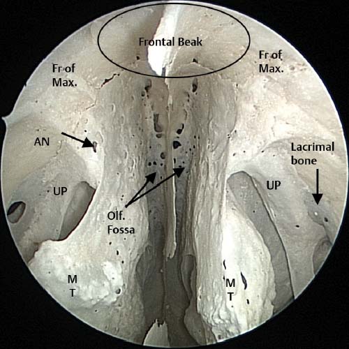
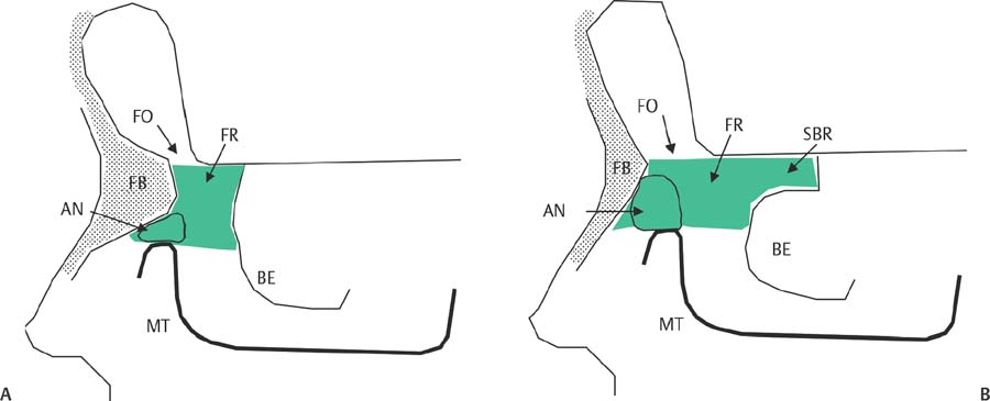
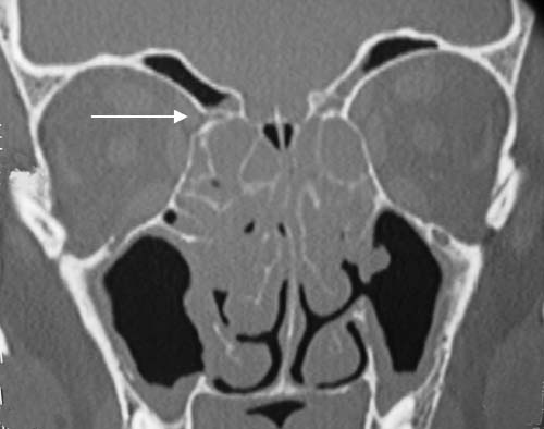
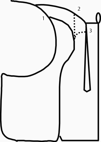
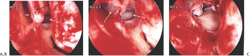
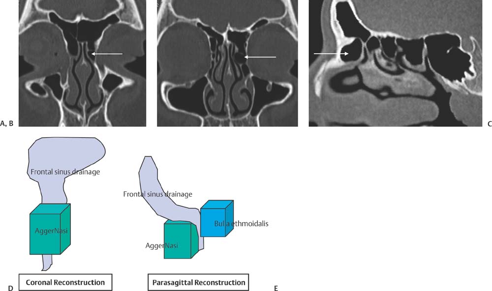
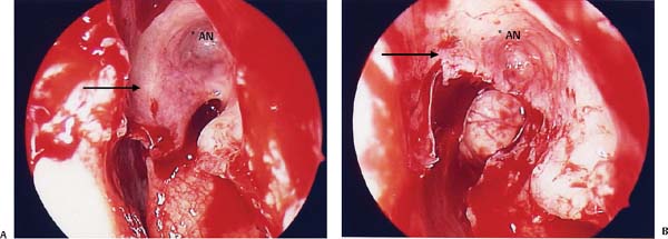
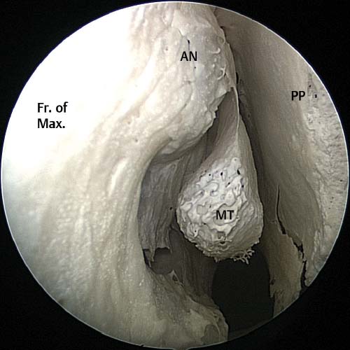
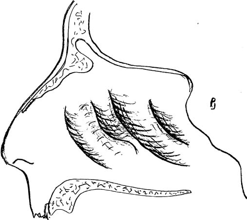
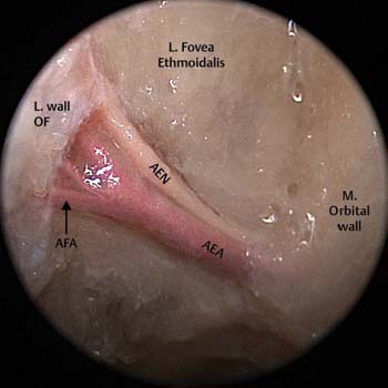
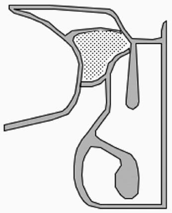
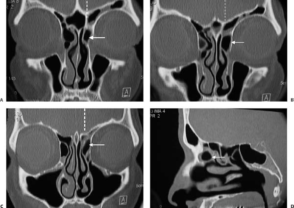
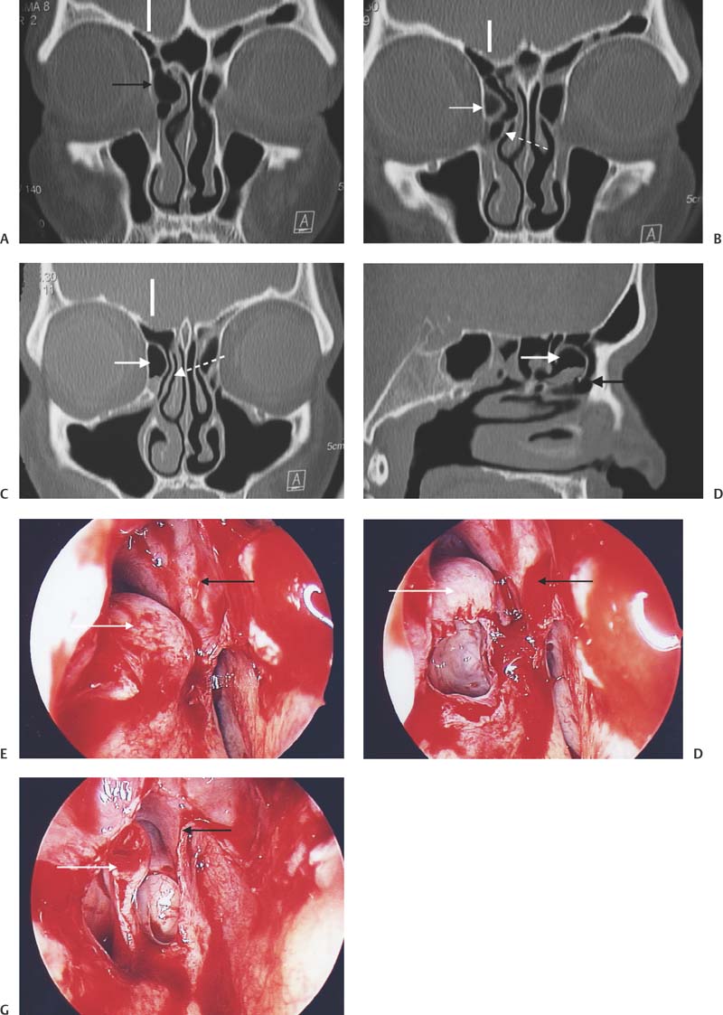
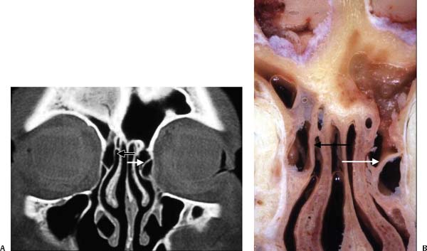
6 In recent years endoscopic sinus surgery (ESS) has become accepted as the treatment of choice for chronic sinusitis that is resistant to medical management.1 As ESS has become more widely adopted so the understanding of the complex and varied anatomy of the sinuses has improved.2,3 However, the frontal recess and frontal sinus remain a challenge for surgeons. The anatomy is complex, varied, and can be confusing.4,5 To better understand the anatomy of the paranasal sinuses, it is important to be aware of the embryology of the turbinates and sinuses. There are six embryological lamellae, or “ridges,” that form from the lateral nasal wall and give rise to important structures in the nose. Early in the fetal development these lamellae fuse to form four lamellae. Persistence of the fifth lamella will result in the presence of a supreme turbinate. This is rare and only present in 15% of the population. The first lamella forms the uncinate process, the second the bulla ethmoidalis, the third the middle turbinate, the fourth the superior turbinate, and the fifth (if present) the supreme turbinate (Fig. 6.1). The frontal, anterior ethmoid, and maxillary sinuses pneumatize from the furrow between the uncinate and bulla ethmoidalis. The posterior ethmoids pneumatize from the furrow between the middle and superior turbinates and the sphenoid sinus from the furrow above the superior turbinate. The key to safe surgery in the frontal recess is a clear understanding of the anatomy. This chapter explains how two- dimensional (2D) computed tomography (CT) scans in coronal, parasagittal, and axial planes can be used to create a three- dimensional (3D) picture of the anatomy of the frontal recess. Such a 3D picture allows the surgeon to plan a surgical approach to the frontal recess so that each cell in the frontal recess can be entered in a predetermined sequential manner and then removed. This allows the surgeon to be able to turn to the CT scan at any point during the dissection and identify the cell that is currently being dissected. This mental picture gives the surgeon greater confidence that the complex anatomy of the frontal recess and frontal sinus is fully understood and removal of obstructing cells can be safely achieved. Insecurity during dissection in the frontal recess may result in either inadequate surgery with ESS failure or may increase the risk of injury to the skull base, orbit, and the anterior ethmoid artery.4,6 A common reason for ESS failure is inadequate removal of cells obstructing the outflow of the frontal sinus.4,6 The location of the frontal recess creates anxiety for the surgeon as operating in this region places the lateral wall of the olfactory fossa (the thinnest part of the skull base), the anterior skull base (fovea ethmoidalis), the anterior ethmoidal artery, and the orbit at risk. The anterior wall of the frontal recess is formed by the thick bone of the frontal process of the maxilla, the so-called “beak” of the frontal process (Fig. 6.2). The size of this beak will vary according to the degree of pneumatization of the agger nasi cell. If there is a large agger nasi cell then the beak will be small. If, however, the agger nasi cell is absent or under-pneumatized, then the beak will extend significantly into the frontal recess and create a narrow frontal ostium as the beak approaches the forward projecting anterior skull base. Thus the antero-posterior distance from the skull base to the frontal beak is largely determined by the pneumatization of the agger nasi cell (Fig. 6.3). The medial wall of the frontal recess is formed by the lateral wall of the olfactory fossa. The height of this wall is determined by the level of the cribriform plate. Keros7 classified the depth of the olfactory fossa as a Keros type 1 (< 3 mm), type 2 (3–7 mm), and a type 3 (> 7 mm). Depending on the Keros type, a variable amount of the lateral wall of the olfactory fossa will be exposed during dissection in this region. The bone of the lateral wall of the olfactory fossa varies in thickness between 0.05 and 0.2 mm and provides little resistance to penetration.8 Fig. 6.1 This drawing demonstrates the four lateral lamellae and the corresponding structures into which they develop. The lateral wall of the frontal recess is formed by the lamina papyracea and the posterior wall by the upward continuation of the anterior face of the bulla ethmoidalis. On occasion this anterior wall of the bulla ethmoidalis may not reach the skull base and a suprabullar recess is formed (Fig. 6.3). The frontal recess is then continuous with this recess. The roof of the frontal recess is formed by the fovea ethmoidalis. This bone is relatively thick and normally provides significant resistance to penetration. In a study conducted in our department we found that the right fovea ethmoidalis was higher than the left in 59% of patients.9 It should also be noted that the roof (fovea ethmoidalis) may slope, thereby placing the medial aspect of the roof at a lower level than the lateral aspect. The anterior ethmoidal artery and nerve runs across the fovea ethmoidalis at a 45-degree angle from lateral to medial (Fig. 6.4). In most instances it can be found behind the upward continuation of the bulla ethmoidalis. However, when this is absent and a suprabullar recess is present, the anterior ethmoidal artery will be in the frontal recess. The anterior ethmoidal artery may lie in a mesentery suspended from the skull base in 14 to 43% of patients (in our study the incidence was 34%).9 It is important that the CT scan is reviewed carefully before surgery to establish if the anterior ethmoidal artery is against the skull base or in a mesentery and if a suprabullar recess is present or not (Fig. 6.5). Fig. 6.2 Endoscopic image of dry skull demonstrating the dry bone anatomy of the frontal recess and frontal beak. Both frontal processes of the maxilla (Fr of Max) join in the midline to form the frontal beak. The olfactory fossa (olf. fossa) are bounded by the middle turbinates (MT) and the nasal septum, and roofed by the cribriform plate. The location of the agger nasi cell (AN) is shown, and the extent of pneumatization of this cell will determine the size of the frontal beak. UP, uncinate process. Fig. 6.3 (A) The effect of a small under-pneumatized agger nasi cell (AN). The frontal beak (FB) is large and the anteroposterior diameter of the frontal ostium (FO) small. The frontal recess (FR) is shaded and extends from the beak to the bulla lamella (BE). (B) The effect of a well pneumatized agger nasi cell (AN) cell with a small frontal beak (FB) and large frontal ostium. If the bulla lamella does not reach the skull base, a suprabullar recess (SBR) is formed. MT, middle turbinate. Fig. 6.4 A cadaveric image taken of the left fovea ethmoidalis demonstrating the anterior ethmoidal artery (AEA) and nerve (AEN) leaving the orbit and travelling in a 45-degree angle from lateral to medial along the skull base. This artery can be seen giving off the anterior falcine artery (AFA) as it approaches the lateral wall of the olfactory fossa (L. wall OF). M, orbital wall, medial orb. Fig. 6.5 The right anterior ethmoidal artery is on a mesentery (white arrow). Note the pinching of the lamella papyracea as the artery exits the orbit. If the anterior ethmoidal artery is cut during surgery (this is only likely if it is on a mesentery) it may retract into the orbit and cause bleeding within the orbital tissues. This creates an increase in the intraorbital volume with resultant proptosis. Increasing pressure stretches the optic nerve and may result in decreased arterial blood flow to the retina and subsequent loss of vision. The uncinate process, in the past, was thought to be the key to the frontal recess.8 This text adopts an alternate approach and suggests that the agger nasi cell is the key that unlocks the frontal recess.10,11 The agger nasi cell is present in more than 90% of patients.12 As the agger nasi cell is the key, it is important to understand the interaction between the uncinate and the agger nasi cell. The interaction between the upward continuation of the uncinate and the agger nasi cell is often poorly understood. The attachment of the root of the uncinate into either the lamina papyracea, skull base, or middle turbinate have been well described (Fig. 6.6),5,8,13 but how this upward continuation of the uncinate interacts with the agger nasi cell and anterior ethmoidal cells in the frontal recess is sometimes poorly understood. Fig. 6.6 The classical description of the insertions of the uncinate process.8 1, insertion into the lamina papyracea; 2, insertion into the skull base; 3, insertion into middle turbinate. In most cases the uncinate/medial wall of agger nasi cell implants on the lamina papyracea. In a large proportion of these patients, this upward extension will give off a leaflet of bone to the bulla lamella forming a plate of bone that divides the frontal recess vertically from posterior to anterior14,15 as it extends from the bulla ethmoidalis to the medial wall of the agger nasi cell and onto the frontal beak. In this situation the frontal sinus will drain medial to this plate (Fig. 6.7). Fig. 6.7 Intraoperative pictures in the right frontal recess illustrating (A) the upward continuation of the uncinate (black arrow) forming the medial wall of the agger nasi cell (AN). (B) The further removal of the medial wall/uncinate superiorly reveals the roof of the agger nasi cell (AN) and frontal ostium (FS). (C) A small residual part of the roof of the agger nasi cell remains. The frontal sinus ostium (FS) can be seen. The relationship of a single large agger nasi cell to the frontal sinus ostium is better understood by viewing the coronal and parasagittal scans. This example shows the simplest anatomical configuration of the frontal recess. The next important step is to decide where the frontal sinus drains in relation to these cells.16–18 This concept is illustrated in Fig. 6.8. The second anatomical variation to consider is that of a larger agger nasi cell. A large cell may push the upward continuation of the uncinate medially so that it attaches to the middle turbinate (Fig. 6.9). Fig. 6.8 Coronal and parasagittal scans illustrating a single agger nasi cell (white arrow) on the left side. Note that the three-dimensional building block reconstructions have been done in the anteroposterior (coronal) and parasagittal planes. Fig. 6.9 A diagram illustrating how a single large agger nasi cell pushes the insertion of the uncinate onto the middle turbinate. This configuration alters the drainage of the frontal sinus as the agger nasi cell pushes the frontal drainage pathway posteriorly. Therefore, the surgeon can no longer access the frontal recess medial to the uncinate. Access is obtained by passing the curette along the frontal sinus drainage pathway behind the posterior wall of the agger nasi cell and fracturing the posterior wall and roof of the agger nasi cell forward to fully expose the frontal ostium. The following series of CT scans and operative dissection pictures illustrates the upward continuation of the uncinate which forms the medial wall of the agger nasi cell and has been pushed by this cell to insert on the middle turbinate before progressing superiorly, forming the roof of the agger nasi and then implanting on the lamina papyracea (Figs. 6.10 and 6.11). The third scenario involves the further upward continuation of the uncinate onto the skull base. In a small percentage of patients the uncinate may have no relationship with the agger nasi cell. Usually in this configuration the uncinate will progress superiorly to implant on the skull base. The following series of CT scans and anatomical dissections illustrates this variation (Fig. 6.12). The uncinate can be seen passing medial to the agger nasi cell and implanting at the junction of the middle turbinate and skull base. The broken line indicates the position of the parasagittal scan. Alternatively the uncinate process may form the medial wall of a frontoethmoidal cell that is sitting above the agger nasi cell. This frontoethmoidal cell may push the upward continuation of the uncinate superiorly to attach onto the skull base (Fig. 6.13). The variations associated with the frontoethmoidal cells are considered later, in the discussion on the classification of the frontal ethmoidal cells. The following cadaver dissection and CT scan illustrate a cell on the right side pushing the insertion of the uncinate onto the skull base (Fig. 6.13). There are a large number of possible variations in the anatomy of the frontal recess. To gain a functional understanding of the anatomy of the frontal recess the simplest configurations should be understood first before more complex variations are tackled. The simplest anatomical configuration is the single agger nasi cell without frontal ethmoidal cells. The agger nasi cell is the most anterior ethmoidal cell and is present in 93% of people.12 The agger nasi cell forms a bulge on the lateral nasal wall anterior to the middle turbinate (Fig. 6.14). If sequential coronal CT scans are evaluated in an anterior to posterior direction, the agger nasi cell can be seen before the middle turbinate comes into view (Fig. 6.15).5,12 Note that the uncinate only has a relationship with the posterior half of the agger nasi cell and not the anterior half which is why the uncinate cannot be seen on the coronal CT scans taken through the anterior half of the agger nasi cell, as seen in Fig. 6.15. This relationship can be viewed in Figs. 6.16 and 6.17. The surgeon reviewing a patient’s CT scans before surgery needs to understand how the anterior coronal CT scan through the agger nasi cell relates to the frontal beak and frontal sinus and how to be able to tell on sequential coronal CT scans when the transition from frontal sinus to frontal recess occurs. Figure 6.16 is a diagrammatic illustration of how a coronal CT scan through the anterior half of the agger nasi cell and through the frontal sinus can be identified on a coronal CT scan. Fig. 6.10 The agger nasi cell is indicated by the white arrow. The broken line indicates the position of the parasagittal scan. The scans follow the sequence A, B, C, and D. The uncinate can be seen to be pushed medially by the agger nasi cell, touching the middle turbinate before it turns more posteriorly to form the posterior wall and roof of the agger nasi and implanting on the lamina papyracea. Fig. 6.11 These left-sided operative pictures are taken of the patient in Fig. 6.10. The black arrow indicates the uncinate process which forms the medial wall of the agger nasi cell and attaches to the middle turbinate before progressing superiorly to form the roof of the agger nasi cell and implanting on the lamina papyracea. Fig. 6.12 (A–D) On the right side (in CT scans B, C, and D) the white arrow indicates the agger nasi cell. The black arrow indicates the space anterior to the agger nasi cell in scans (A) and (D). The solid white vertical line in (A), (B), and (C) indicates the position of the parasagittal scan (D). The broken white arrow indicates the uncinate process separate from the agger nasi cell in scans (B) and (C). (E–G) These are the right-sided operative pictures of the CT scans shown in (A–D) and (E) corresponds to CT scan in (A) and shows the agger nasi cell intact (white arrow) and the black arrow indicating the uncinate process as it progresses upward to implant on the junction of the middle turbinate and the skull base. (F) The anterior face of the agger nasi cell opened with the uncinate process (black arrow) seen to be separate from the agger nasi cell. (G) The uncinate (black arrow) implanting onto the skull base. The white arrow indicates the remaining roof of the agger nasi cell. Fig. 6.13 The CT scan is taken of the cadaver dissection specimen pictured along with it. On the right side, the uncinate process (black arrow) is pushed up toward the skull base and onto the middle turbinate by a small cell sitting above and medial to the agger nasi cell. On the left the upward continuation of the uncinate can be seen forming the roof of the agger nasi cell (white arrow). Note the frontal sinus draining directly above the agger nasi cell. Fig. 6.14 Endoscopic image of a dry skull taken within the right nasal cavity. The bulge on the lateral nasal wall created by the agger nasi cell (AN) can clearly be seen above and anterior to the middle turbinate (MT). Fr. of Max, frontal process of maxilla; PP, perpendicular plate. Fig. 6.15 CT scan illustrating agger nasi cells anterior to middle turbinate insertion (white arrows). If line 1 is drawn in the coronal plane, the frontal beak can be seen as continuous ridge of bone with the frontal sinus above it (diagonally shaded area in Figs. 6.16 and 6.17). This line (line 1) is anterior to the uncinate and one can still see the continuous ridge of bone of the beak (floor of the frontal sinus). This makes it simple to differentiate the frontal sinus (above the beak) from the frontal recess. Line 2 in Fig. 6.17 shows a coronal cut through the uncinate process behind the beak. This illustrates the transition from the frontal sinus to the frontal recess with loss of the continuity of bone (illustrated as the “frontal beak” in Fig. 6.16) and by the presence of the uncinate. This coronal cut illustrates the posterior part of the agger nasi cell’s relationship to the superior extension of the uncinate process. This part of the uncinate forms the medial and posterior medial wall of the agger nasi cell and represents the relationship between the anterior agger nasi cell (shaded with dots) and the frontal beak and the floor of the frontal sinus (diagonally shaded area). Fig. 6.16 An illustration of a parasagittal view of the agger nasi cell with line 1 representing a coronal cut through the anterior aspect of the agger nasi cell anterior to the middle turbinate. The diagonally striped shaded area represents the area of the frontal sinus above the frontal beak (black arrow). The diagonally shaded area in Figs. 6.16 and 6.17 is the frontal sinus above the frontal beak. The frontal beak forms the floor of the frontal sinus (Fig. 6.2). Frontal ethmoidal cells pushing into this shaded area are classified as Kuhn type 3 cells (Table 6.1).14 From these diagrams it can be seen that most of the agger nasi cell is anterior to the uncinate but the posterior half of the agger nasi cell has an intimate relationship with the upward extension of the uncinate process (Fig. 6.18).10 The surgeon should also be able to differentiate on the axial scans when transition occurs from the frontal sinus to the frontal recess. The frontal sinus scans should be viewed from the top down (cranial to caudal). The frontal sinus is relatively easy to identify because, as it narrows toward the frontal ostia, it forms a square (Fig. 6.19). At this level the posterior wall of the two frontal sinuses forms a straight line (Fig. 6.19B). As the skull base turns posteriorly these squares elongate posteriorly but still maintain a roughly rectangular shape. This is the transition stage from frontal sinus to frontal recess (Fig. 6.19D,E). As the posterior ends of these boxes become pointed the scans reach the frontal recess (Fig. 6.19E). Figure 6.19A,B shows the square formation of the frontal sinuses. The transition region is between Fig. 6.19D and Fig. 6.19E. Note how the bone of the anterior wall changes at each of these levels. At Fig. 6.19A,B, the bone of the anterior wall of the frontal sinus is even and relatively flat and not very thick. The anterior wall bone becomes much thicker as the upper region of the frontal beak is reached (Fig. 6.19C). At Fig. 6.19D,E the anterior wall is curved indicating that the nasion has been reached. In Fig. 6.19D the nasion is fully developed and the frontal beak bone is thick. Also note how the posterior wall has become pointed (Fig. 6.19D,E) as the axial cut goes into the frontal recess toward the anterior ethmoidal arteries. This artery is seen in its canal in Fig. 6.19D on the right side. Fig. 6.17 An illustration of the parasagittal view with line 2 representing a more posterior coronal cut through the posterior aspect of the agger nasi cell. Table 6.1 Kuhn Classification of Frontal Recess and Frontal Sinus Cells
Anatomy of the Frontal Recess and
Frontal Sinus with Three-Dimensional
Reconstruction
 Basic Anatomy of the Frontal Recess and Frontal Sinus
 The Uncinate Process
Attachment of the Uncinate to the Lamina Papyracea
Attachment of the Uncinate to the Middle Turbinate
Attachment of the Uncinate to the Skull Base
The Agger Nasi Cell10 (Video 10)
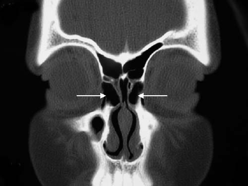
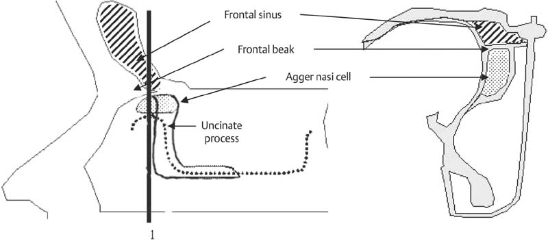
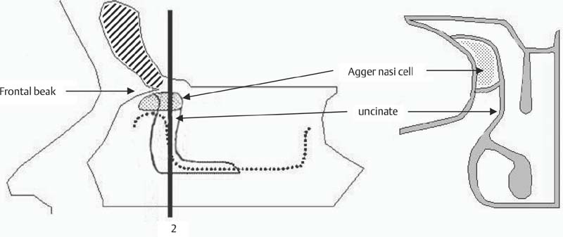
The Transition from Frontal Sinus to Frontal Recess on the Coronal CT Scans
Transition from Frontal Sinus to Frontal Recess on the Axial Scans
Agger nasi cell |
|
Supraorbital ethmoid cells |
|
Frontal cells |
|
• Type 1 | Single frontal recess cell above agger nasi cell |
• Type 2 | Tier of cells in frontal recess above agger nasi cell |
• Type 3 | Single massive cell pneumatizing cephalad into frontal sinus |
• Type 4 | Isolated cell in the frontal sinus |
Frontal bulla cells |
|
Suprabullar cells |
|
Interfrontal sinus septal cell |
|
Source: Data from Kuhn FA. Chronic frontal sinusitis: the endoscopic frontal recess approach. Operative techniques. Otolaryngol Head Neck Surg 1996;7:222–229.
Frontal Ethmoidal Cells
Classification
A single agger nasi cell in the frontal recess is only one of the many anatomical variations. In 1995 Fred Kuhn classified the cells seen in the frontal recess and frontal sinus as presented in Table 6.1.14
This classification still forms the basis of our current classification although we have made significant modifications (Table 6.2). One of the important modifications is defining the types of cells that occur in the frontal recess and frontal sinus more precisely. The first cells to be considered are the frontal ethmoidal cells. For a cell to be called a frontal ethmoidal cell it needs to satisfy two criteria: first it must be an anterior ethmoidal cell and second it should be in close proximity to the frontal process of the maxilla. The frontal process of the maxilla is the bone forming the anterior wall of the frontal recess (Figs. 6.2 and 6.20).
This bone goes on to form the frontal beak. The frontal ethmoidal cells are further divided depending on how many there are and how far these cells extend into the frontal sinus through the frontal ostium.16 Kuhn classified frontal ethmoidal cells into types 1 to 4.14 However, we have modified this classification by clearly defining a frontal ethmoidal cell and by redefining the type 3 and 4 cells (Table 6.2).
 The Building Block Concept for the Reconstruction of the Anatomy of the Frontal Recess
To reconstruct the cells in the frontal recess in three dimensions, building blocks are arranged, one block for each cell.10,18 This is done as an aid to the dissection of the frontal recess. When operating in this area the surgeon needs to know exactly which cell is being dissected and in what sequence each cell will be opened so that the frontal recess can be safely and competently cleared. To build a mental picture of the cells in the frontal recess, the coronal CT scans are viewed first. The first cell seen on the coronal CT that is anterior to and directly above the insertion of the middle turbinate is, in most cases, the agger nasi cell10,18 (Fig. 6.14). This cell should now be identified on the parasagittal CT scan (Fig. 6.21). Make sure that you use all the information available to you to confirm that the cell seen on the coronal is indeed the cell that you have identified on the parasagittal. Ask yourself if the cell has air or whether it is partially or completely opacified. Check on both the coronal and para-sagittal scans that the cell that you have identified has the expected amount of opacification. A building block is now placed for this cell (Fig. 6.21).
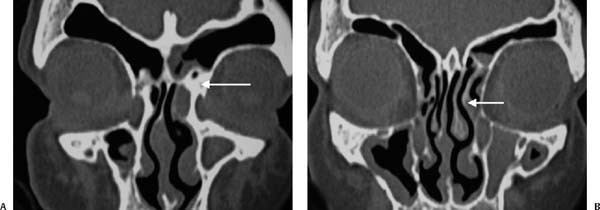
Fig. 6.18 (A) Coronal CT scan anterior to uncinate with the floor of the frontal sinus (“beak”) illustrated by white arrow on the left. (B) Coronal CT through the uncinate process (white arrow) with the uncinate forming medial wall and roof of agger nasi cell on the left.
Stay updated, free articles. Join our Telegram channel

Full access? Get Clinical Tree


