Evaluation of Refractive Error and Pre- and Postoperative Data
CHAPTER CONTENTS
Binocular Fog Manifest Refraction
Cycloplegic Retinoscopy and Refraction
Computerized Corneal Topography
High-Frequency Anterior Segment Ultrasound Biomicroscopy
Before undergoing refractive surgery, a candidate’s refractive error and other preoperative data, such as that from pachymetry and topography, must be evaluated to ensure consistent and accurate surgical results. Likewise, postoperative data need to be evaluated to decrease the likelihood of complications and to increase the possibility of favorable surgical results. Autorefraction may provide a useful starting point for baseline preoperative refraction but should not be used for postoperative testing because it often gives erroneous results (Fig. 6-1).
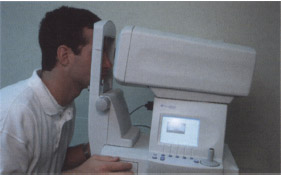
Figure 6–1 The autorefractor by Humphrey gives spectacle refractive error and K values.
RETINOSCOPY
Indications
- starting point for determination of a patient’s manifest refractive error (required of all refractive surgery candidates)
Methods
- Enter the correct distance pupil diameter into the phoropter.
- Place the phoropter in front of the patient, making sure it is level with the patient’s head.
- Relax accommodation by “fogging” the patient with plus-power lenses, placing a moderate amount of spherical plus power over the patient’s habitual prescription into the phoropter (+1.50 to +2.00 D).
- Present the 20/60 line of Snellen’s chart to each individual eye. (If the line is too blurry to read with either eye, the patient is adequately fogged.)
- Present a 20/400 distance target (e.g., the “E” from Snellen’s chart) to the patient for fixation using both eyes (OU).
- Perform retinoscopy one eye at a time while OU are unoccluded.
- Do not remove the retinoscopic working-distance lenses (usually +1.50 D) from the phoropter (can trigger patient accommodation).
- Adjust the working-distance lenses accordingly if you perform retinoscopy particularly close to or far from the phoropter.
- Record the retinoscopic findings for comparison with manifest refraction results.
- Note the retinoscopic reflex (should be bright and clear, not dull).
- Note any “scissoring” of the reflex motion (a hallmark sign of keratoconus).
- Proceed directly to binocular fog manifest refraction.
BINOCULAR FOG MANIFEST REFRACTION
Myopia
- determination of refractive error with a phoropter after retinoscopy (for all patients)
Methods
- Follow these steps carefully to reduce chances of over-minus refractive results.
- Fog with plus-power lenses to relax accommodation. [Initially, fog the right eye (OD) by +1.50 D and the left (OS) by +3.00 D.]
- Note that myopes can easily accept too much minus power for their manifest refraction endpoint if not properly fogged (results in postoperative overcorrection).
- If retinoscopy immediately preceded manifest refraction, OD should already be fogged and so simply add another +1.50 D over OS to complete the initial fogging (see section on Retinoscopy).
- With both of the patient’s eyes unoccluded, present the isolated 20/60 line from Snellen’s chart.
- Inform the patient that vision for OU should be fuzzy, with vision for the left eye being extremely fuzzy. (Patients should guess at letters during the exam if unsure).
- Emphasize the importance of keeping OU open for the duration of testing.
- Begin binocular fog manifest refraction for the right eye (OD) by slowly stepping down the patient from plus-sphere power while presenting successively smaller isolated acuity lines from Snellen’s visual acuity chart.
- Ask the patient to read the acuity line that is presented with each 0.25 D decrease in plus-sphere power.
- Stop decreasing plus-sphere power when the patient is able to just see the smallest achievable acuity line without noticing any minification of the letters.
- Ask the patient to read the acuity line that is presented with each 0.25 D decrease in plus-sphere power.
- Refine the cylinder amount and axis OD using the phoropter’s Jackson crossed cylinder (JCC) and one line larger than the patient’s smallest achievable acuity line as the target.
- Fog OD again with enough plus power to blur the 20/50 line.
- Slowly step the patient out of plus power, asking the patient if the final step-down lenses make the target line clearer and easier to read or just smaller and darker (minified).
- If the patient notices minification of the letters but acuity does not improve, then the patient is probably over-minused in power. This is the monocular endpoint for OD. [Mild over-minus power (−0.25 to −1.00 D) can make distance targets appear subjectively “darker” and, therefore, falsely “clearer” to the patient.]
- Slowly step the patient out of plus power, asking the patient if the final step-down lenses make the target line clearer and easier to read or just smaller and darker (minified).
- After this final step down from plus-sphere power, isolate the line of the patient’s best corrected visual acuity (BCVA).
- Double check that the monocular end-point is correct by adding two or three “clicks”of plus-sphere power (+0.50 to +0.75 D) over OD. (The patient should require no more than 0.50 to 0.75 D of plus power to blur out the BCVA line; if more plus power is required, then the patient is over minused.)
- After reaching the monocular endpoint for OD (see above), keep the right eye unoccluded and fog it by +3.00 D.
- Decrease plus-sphere power in OS until he or she is just able to see the 20/60 line of Snellen’s chart.
- Repeat the steps used for OD for OS.
- After reaching the manifest refraction monocular endpoint for both OD and OS, balance the patient for binocular accommodation (see page 48 for balance techniques).
Hyperopia
Indications
- See section on myopia for indications.
Methods
- The procedure for binocular fog manifest refraction of hyperopes is identical to that for myopes.
- Follow the steps for myopic binocular fog manifest refraction carefully to reduce the chance of underestimating the true amount of plus power of the refraction. (Hyperopes may not accept full plus power on the manifest refraction end-point if they are not properly fogged, and even with proper fogging, they still may not accept the full amount of plus power discovered on retinoscopic evaluation (i.e., latent hyperopia.)
- Proceed to a cycloplegic examination to reveal the actual amount of hyperopia for patients with suspected latent hyperopia.
Astigmatism
Indications
- to confirm the amount of astigmatism found with retinoscopy, keratometry, and corneal topography (usually agrees)
- Compensation for over-minus sphere power by approximately twice the amount of plus cylinder power is a relatively common error found in spectacle prescriptions.
- For example, if a patient’s true prescription is −6.00 + 2.00 x 090, he or she may actually have an inaccurate prescription of −7.00 + 4.00 x 090 (avoid by making sure that retinoscopy results correspond with manifest refraction results).
- Compensation for over-minus sphere power by approximately twice the amount of plus cylinder power is a relatively common error found in spectacle prescriptions.
- to quantify the amount of astigmatism in infrequent cases of almost total noncorneal (i.e., lenticular or ocular) astigmatism (usually much greater than that found on keratometry or corneal topography)
- to evaluate the consistency of the corneal topographical cylinder with reconstruction of the sphero-cylindrical manifest refraction (Fig. 6-2) in the infrequent cases of nonorthogonal astigmatism (i.e., the two steep meridians differ by more than 180 degrees)
Methods
- The procedure for astigmatic binocular fog manifest refraction is exactly the same as that described for myopic-binocular fog manifest refraction.
- If you cannot reconcile retinoscopic results with manifest refraction results, perform a cycloplegic retinoscopy and manifest refraction.
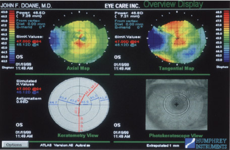
Figure 6-2 A topographical map shows a patient with nonorthogonal corneal astigmatism.
BINOCULAR BALANCING
Indications
- mandatory matching of accommodative stimulus for OU for all surgical candidates who may have some accommodative ability in reserve (i.e., patients younger than 60 years of age)
- corroboration of initial results [If you strictly followed the steps for binocular fog manifest refraction (see page 46), most patients are already balanced for accommodation.
Methods
- Determine the patient’s dominant eye before attempting binocular balance (see Chapter 5 for eye dominance testing).
- Generally perform balance techniques with a phoropter after arriving at the monocular endpoints for binocular fog manifest refraction.
- If a patient cannot be equally balanced by any method, leave the dominant eye with clearer vision. (See Chapter 5 for tests to determine eye dominance.)
Fogged Prism Disassociated Balance
Methods
- Make sure both of the patient’s eyes are open behind the phoropter.
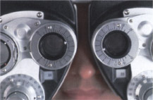
- Fog each eye to slightly over the monocular endpoint obtained with binocular fog manifest refraction by +0.75 D sphere power (Fig. 6-3).
- Isolate one or two acuity lines worse than the patient’s BCVA line on the projected distance chart.
- Place three prism diopters base down (BD) over OD and three base up (BU) over OS using the phoropter’s rotary (Risley’s) prisms.
- Inform the patient that he or she should see two “fuzzy” lines of letters, one above the other.
- If the patient sees only one line, try increasing the vertical prism to four to six prism diopters over each eye and make sure OU are open.
- If OU are open but the patient still sees only one line, abandon this balance procedure for one of the others described in this section.
- Instruct the patient to look at both lines with OU and report if one line looks clearer or if both lines appear equally fuzzy. (If equally fuzzy initially, then the patient is already balanced and the procedure is complete.)
- Add +0.25 D sphere power to the eye that sees the clearer line (i.e., make it blurrier). [If the lower line is clearer (the one seen by OS) then add +0.25 D to OS.]
- Ask the patient again if both lines are equally blurry.
- If not, ask the patient again which line is clearer and add +0.25 D to the eye seeing the clearer line.
- The endpoint is reached when the patient reports that both lines are equally clear or nearly equally clear. (If the patient cannot decide which line is clearest, then the patient cannot be balanced and you should leave the patient’s dominant eye clearer by 0.25 D.)
- After achieving the endpoint, remove the prisms and step down the patient from plus-sphere power until the patient can read the BCVA line sharply without noticing any binocular minification of the letters.
- Record the resulting numbers for each eye as the patient’s manifest refraction.
Red-Green Prism Disassociated Duochrome Balance
Indications
- an alternative to the fogged prism disassociated balance procedure. (With this method, accommodation is uncontrolled and over minus results are possible because the patient is not fogged during testing.)
- the only way to balance a patient with amblyopia (individually balances each eye under equal conditions simultaneously; each eye has a different BCVA with eye-glasses)
Methods
- Unocclude OU behind the phoropter.
- Isolate one line on Snellen’s chart that is larger than the patient’s BCVA line.
- Do not fog either eye.
- Cover the isolated line with the red-green filter.
- Using the phoropter’s Risley’s prisms, place three prism diopters BD over OD, and three BU over OS.
- Inform the patient that he or she should see two lines, one above the other.
- If the patient sees only one line, make sure OU are open.
- If patient’s eyes are both open, increase the vertical prism to 4 or 6 D over each eye.
- If the patient still does not see two lines, invert the prisms (i.e., place BU over OD and BD over OS).
- If the patient still cannot see two lines, abandon the procedure for one that does not involve prism disassociation, such as fogged alternate cover balancing.
- If the patient sees only one line, make sure OU are open.
- Instruct the patient to look at the upper line only (the one seen by OD) while keeping OU open.
- Tell the patient to look from the green side to the red side and then back to the green side.
- Ask which side looks sharper and clearer or if both sides look equally clear.
- If the green side is clearer, add -0.25 D to OD only; if the red side is clearer, add −l0.25 D to OD.
- If both the red and green sides look equally clear initially, proceed to balancing OS (i.e., direct the patient to look at the lower line).
- Tell the patient to look from the green side to the red side and then back to the green side.
- The endpoint for OD is achieved when both sides appear equally clear. (If both sides are not equally clear and the patient cannot decide which one is clearer, leave the green side clearer than the red side by 0.25 D.)
- Direct the patient’s attention to the lower line (the one seen by OS), and repeat the steps described for OD using the same endpoint criterion.
- If a patient always chooses the same side (red or green) as clearer regardless of which lens is presented, abandon the duochrome test for another balancing method.
- Record the endpoints for OD/OS as the manifest refraction results.
Fogged Alternate Cover Balance
Indications
- an alternative to fogged prism disassociated and red-green prism disassociated duochrome balance methods for patients unresponsive to those tests
Methods
- Fog each eye +0.75 D sphere power over the endpoint of binocular fog manifest refraction behind the phoropter.
- Isolate one or two acuity lines worse than the patient’s BCVA line on Snellen’s acuity chart.
- Instruct the patient to keep OU open during testing.
- Inform the patient that he or she should see one “fuzzy” line.
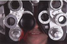
- Alternately cover the viewing holes in the phoropter with a cover paddle for each eye (Fig. 6-4).
- Cover and uncover each eye a few times and ask the patient to notice if one line appears clearer or if OU appear to have equally blurry vision.
- If one eye appears to have clearer vision, add +0.25 D sphere power over that eye only.
- Continue alternately covering the eyes and adding +0.25 D sphere power until the lines are equally blurry, the endpoint of the test.
- If unable to achieve equality, leave the patient’s dominant eye clearer but leave the nondominant eye as clear as possible.
- If OU appear equally blurry initially, then the patient is already balanced and further balance testing is unnecessary.
- If unable to achieve equality, leave the patient’s dominant eye clearer but leave the nondominant eye as clear as possible.
- If one eye appears to have clearer vision, add +0.25 D sphere power over that eye only.
- After achieving the endpoint, step down the patient from plus sphere power (binocularly) until the BCVA line is clear and sharp but the patient notices no minification of letters.
- Record the resulting numbers for each eye as the patient’s manifest refraction.
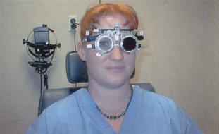
TRIAL FRAME REFRACTION
Indications
- “fine tuning” of the results of binocular fog manifest refraction and binocular balance (see pages 46 and 48, respectively) when a patient’s spherical equivalent refractive error is more than 4.00 D
- confirmation of results from binocular fog manifest refraction for patients with accommodative instability (Vertex distance can be held constant and peripheral fusion cues are left intact in a trial frame although for patients with very deep-set or proptotic eyes, a trial frame may not achieve the average vertex distance.)
- another option for retinoscopy and binocular fog manifest refraction on patients who are unable to sit behind a phoropter
- generally more accurate refinement of refraction than the phoropter because you can control vertex distance and leave peripheral fusion locks intact
Methods
- Clean trial lenses with a soft, clean lens cloth.
- Place a combination of spherical and cylindrical trial lenses into the trial frame that equal the balanced manifest refraction results for each eye.
- Place the sphere lens in the single well on the back side of the trial frame.
- Place any cylinder lens on the correct axis in the first (closest to the eye) well on the front of the trial frame.
- Lock the cylinder axis in place with the axis lock knob.
- Place any other necessary sphere lenses to equal the manifest refraction result in the middle well on the front side of the trial frame.
- Place the sphere lens in the single well on the back side of the trial frame.
- Place an occluder lens in the last well on the front side of the trial frame over the patient’s nondominant eye (Fig. 6-5). (See Chapter 5 for tests to determine eye dominance.)
- Place the trial frame on the patient and adjust it for the correct temple length to the correct vertex distance, frame height (via nose pad adjustment knob), pantoscopic tilt, and interpupillary distance.
- Inform the patient that he or she can see out of only one eye because an occluder is in place over the nondominant eye.
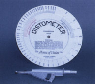
- Measure the vertex distance with a distometer (Fig. 6-6). (For prescriptions >4.00 D, vertex distance becomes significant with respect to power at the cornea.)
- Try to keep a consistent vertex distance between patients to minimize confusion of vertex distance conversions. (Excimer lasers allow for a set vertex distance of 12.5 mm.)
- If you cannot obtain a normal vertex distance, note the actual vertex distance and adjust for power accordingly when necessary. (Vertex distance affects a patient’s acceptance of power for distance vision in the trial frame: above average distance means a patient accepts too much minus power; below average distance indicates that a patient accepts too much plus power.)
- Show the patient his or her BCVA line from Snellen’s acuity chart, and ask the patient to read that line using the unoccluded eye. (If the patient cannot read the line, be sure the sphere and cylinder powers and axis are correct and that the lenses are clean.)
- Refine the sphere power in the trial frame.
- Present a -0.50 D sphere lens over the unoccluded eye and ask the patient if it makes the line clearer and easier to read, or more blurry.
- If the line is more blurry, put the lens aside.
- If the lens makes the letters clearer and easier to read, place a +0.25 D lens in the front well.
- Present a -0.50 D sphere lens over the unoccluded eye and ask the patient if it makes the line clearer and easier to read, or more blurry.
- Re-present the +0.50 D lens. (If the patient still sees more clearly with the lens, remove the +0.25 D lens and add the +0.50 D lens to the front well.)
- Present a +0.50 D lens a final time. (If the line is still clearer, then the manifest refraction results are probably wrong.)
- Next, present a −0.50 D sphere lens over the unoccluded eye, and ask the patient if it makes the line clearer and easier to read, or just smaller and darker (minified).
- Present the −0.50 D lens again. (If the patient still sees more clearly with the lens and does not notice minification of the letters, remove the −0.25 D lens and put the −0.50 D lens in the front well.)
- Present the −0.50 D lens a final time. (If the line is still clearer and not just smaller and darker, then the manifest refraction results are probably wrong.)
- Record the sphere power selected after performing these steps as the trial frame refraction sphere power.
- Refine the cylinder axis if the patient’s astigmatism is more than 0.50 D.
- Inform the patient that he or she will be refining the astigmatism axis.
- Isolate one line worse than the patient’s BCVA line on Snellen’s acuity chart.
- Guide the patient’s corresponding hand (i.e., right hand for the right eye) to the cylinder axis adjustment knob on the trial frame.
- Loosen the axis lock knob.
- Instruct the patient to hold the adjustment knob between the thumb and forefinger and to look at the isolated line.
- Tell the patient to slowly turn the knob forward and backward until the line becomes as clear as possible.
- Patients with only 0.75 to 1.00 D of cylinder power may have arrange of approximately 10 degrees where the letters appear to be equally clear. (In this case, tell the patient to stop turning the knob when in the approximate middle of the “clear range.”)
- If the patient has selected an axis that is significantly different (>5 degrees) than the manifest refraction axis, adjust the axis yourself between the manifest refraction and cylinder axes.
- Ask the patient whether one or two is clearer as you stop at each axis.
- Inform the patient that he or she will be refining the astigmatism axis.
- Record the selected axis as the trial frame refraction axis.
- Unocclude the other eye and place the occluder lens over the eye that has already been refined.
- Repeat the steps for refining sphere power and cylinder axis for the other eye.
- After refining OU, unocclude them and check the patient’s visual acuity with OU on the Snellen’s acuity chart.
- Record the power and axis in the trial frame for each eye as the trial frame refraction.
- These results should be consistent (within +0.50 or –0.50 D spherical equivalent power and within +0.10 or −10 degrees of cylinder axis) with retinoscopic and binocular fog manifest refraction results.
- If results are inconsistent, recheck the results or perform a cycloplegic examination.
- When refining the sphere power in the trial frame, always present plus lenses first to avoid an accommodative response from the patient.
- The spherical endpoint in the trial frame should be no more than ± –0.50 D from the manifest refraction endpoint; if further than this endpoint, the manifest refraction is probably wrong and should be reevaluated.
- You may refine cylinder power in the trial frame with a hand-held cylindrical lens, also known as a Jackson cross cylinder (JCC), that usually has ±0.25 D cylinder of power at ninety degrees (not usually necessary unless the cylinder power is questioned).
CYCLOPLEGIC RETINOSCOPY AND REFRACTION
Indications
- identification of suspected latent hyperopia or accommodative spasm
- evaluation of unexplainable acuity fluctuations during the refractive process (also can be explained by poor tear film)
- investigation of large inconsistencies among retinoscopic, binocular fog manifest refraction, and trial frame refraction results
Methods
- Diligent fogging techniques are unnecessary for cycloplegic retinoscopy and manifest refraction.
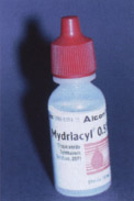
- Tropicamide (1%) (Mydriacil, Opticyl) is usually adequate when performing a cycloplegic examination on adult patients (Fig. 6-7)
- In extreme cases of latent hyperopia or accommodative spasm, you may need to use stronger cycloplegic agents (cyclopentolate 0.5%).
- Administer two drops of 1% tropicamide 10 minutes apart, and begin examination at least 20 minutes after administration of the last drop.
- In extreme cases of latent hyperopia or accommodative spasm, you may need to use stronger cycloplegic agents (cyclopentolate 0.5%).
- For cyclopentolate, the maximum duration of action is longer so it is best to wait 40 to 60 minutes before proceeding with the refractive examination.
- In all cases, perform retinoscopy for a cycloplegic examination before manifest refraction behind the phoropter.
- Record cycloplegic retinoscopic results for each eye.
- Remove half of the retinoscopic working distance lenses (+0.75 D).
- Record cycloplegic retinoscopic results for each eye.
- Occlude OS and perform monocular manifest refraction (MMR) on OD.
- After reaching the MMR endpoint for OD, occlude OD and perform MMR on OS.
- Record the cycloplegic MMR result and the corresponding distance visual acuity for each eye. (If cycloplegic results do not correspond with noncycloplegic results, rely more on the cycloplegic examination for refractive surgical data.)
KERATOMETRY
Indications
- necessary for calculations for intraocular lens implant for clear lens extraction.
- determination of the amount and location of corneal astigmatism
- especially useful if a computerized corneal topographer is unavailable
- comparison of the amount and location of corneal astigmatism with that of manifest refraction cylinder
- especially useful if a computerized corneal topographer is unavailable
- refractive astigmatism
- determination of central corneal power (steepness), which is especially useful for determining the type of microkeratome to use for laser in situ keratomileusis (LASIK)
- determining the integrity of the corneal/tear film surface
Methods (Fig. 6-8)
- Place the patient’s head in the headrest of the keratometer.
- Instruct patient to look at their eye reflected at the end of the tube.
- With one of the patient’s eyes occluded, focus the mires of the keratometer on the cornea of the unoccluded eye.
- Adjust the keratometer dials to achieve the correct alignment of the mires.
- Read the keratometry (K) values from the dials.
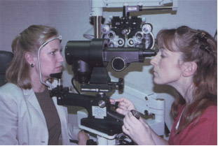
COMPUTERIZED CORNEAL TOPOGRAPHY
Indications
- far superior for most refractive surgical procedures because manual keratometry provides information about only the central 3 mm of the cornea
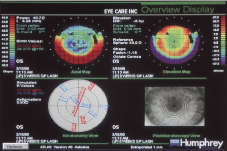
- determines the amount, location, regularity, and type of corneal astigmatism (Figs. 6-9 and 6-10)
- determination of central corneal power
- helps select the best microkeratome for LASIK
- helps determine pre- versus postoperative corneal changes
- helps screen out excessively flat corneas that may not be best treated with refractive procedures that primarily involve further corneal flattening
- helps select the best microkeratome for LASIK
- screening out of preoperative corneal pathology
- identifies forme fruste keratoconus, which often appears as a steep (> 47.00 D) inferior nasal apex with irregular astigmatism or! corneal topography [a contraindication for refractive surgery especially photorefractive keratectomy (PRK) and LASIK] (Fig. 6-11)
- identification of individuals with suspected keratoconus (more than 2.5 D of variation between the superior and inferior K values)
- evaluation of postoperative corneal condition
- especially helps determine the presence or absence of central islands after excimer laser procedures, which are associated with residual myopia (Fig. 6-12)
- helps determine the presence of a decentered ablation after laser refractive surgery (PRK or LASIK) (Fig. 6-13)
- helps determine the presence of irregular corneal astigmatism following incisional keratotomy procedures, which may account for poor postoperative acuity
- especially helps determine the presence or absence of central islands after excimer laser procedures, which are associated with residual myopia (Fig. 6-12)
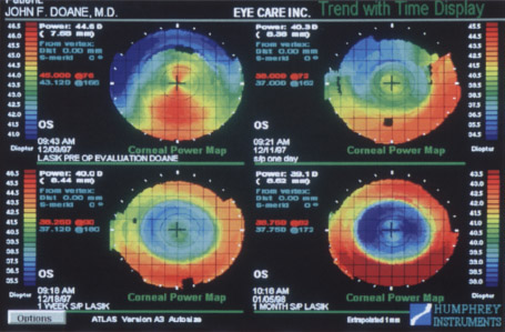
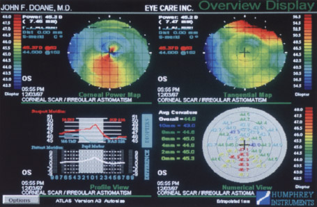
Figure 6-10 A computer topographical printout of a cornea showing irregular astigmatism secondary to a corneal scar.
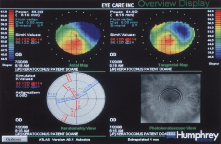
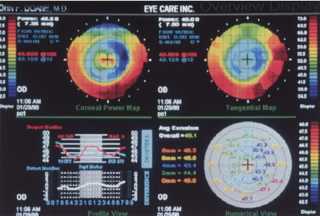
Figure 6-12 A topographical map of a cornea 3 weeks after LASIK that shows a steep central island. The patient showed residual myopia upon manifest refraction.
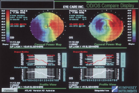
Figure 6-13 A topographical map of a decentered laser ablation zone following LASIK.
- evaluation of the integrity of the tear film/corneal surface interface
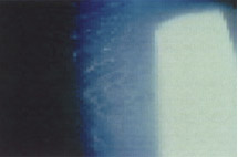
- possible to view reflected corneal mires using the photokeratoscopic view available on most computerized corneal topographers (Fig. 6-14) [indication of a regular corneal surface (normal tear film clear and regular mires) and an irregular corneal surface (abnormal tear film blurred and irregular mires), which may adversely affect surgical results]
- individual assessment of the type and severity of corneal surface abnormalities
Methods
- Place the patient’s head in the headrest.
- With one of the patient’s eyes occluded, focus and center the reflected images on the cornea of the unoccluded eye.
- Capture and process the focused and centered image in the computer.
KERATOSCOPY
Indications
- identification of corneal mires using a battery-powered, light-emitting diode device (Maloney or Van Loenen keratoscopes; JEDMED Instrument Company, St. Louis, MO) that attaches to a standard slit lamp for a magnified, coaxial view or is hand held
- determination of corneal surface regularity and tear film quality for pre- and postoperative evaluations (corneal surface or tear film abnormalities indicated by irregular blurred mires a possible contraindication for some procedures because they suggest irregular astigmatism or keratoconus)
Methods
- Adjust the distance of the keratoscope from the eye until the mires are focused.
- Note the configuration of the mires.
PACHYMETRY
Indications
- evaluation of corneal thickness (540 μm is normal), which guides or impacts some refractive surgery procedures (best to use solid-state ultrasonic pachymeters that are contact activated without a foot pedal, have a digital display, and have the ability to store and print out serial readings, e.g., pachymeters from Zeiss Humphrey Systems, Dublin, CA, or Sonogage, Cleveland, OH) (Fig. 6-15)
- minimum values important for excimer laser refractive procedures (PRK and LASIK), especially in cases where intended ablation correction exceeds a spherical equivalent of 6.00 D
- minimum to maximum (thinnest to thickest) values important for guiding incision depth and order of incisional keratotomy procedures [radial keratotomy (RK) and astigmatic keratotomy (AK); watch for variations of >75 μm see Chapter 8]
- maximum values important for guiding incision depth for limbal relaxing incisions and for guiding initial incision depth for insertion of corneal ring segments (Intacs; KeraVision, Freemont, CA)
- identification of exceptionally low pachymetry values in a patient with high “against the rule” astigmatism (suspected keratoconus)
- minimum values important for excimer laser refractive procedures (PRK and LASIK), especially in cases where intended ablation correction exceeds a spherical equivalent of 6.00 D
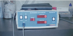
Figure 6-15 A solid-state, ultrasonic pachymeter with digital display and memory.
Methods
- Administer topical anesthesia (optional).
- Take multiple pachymetric readings to ensure consistency.
- Follow the manufacturer’s suggested protocol for use and maintenance (Zeiss Humphrey Systems or Sonogage.)
SPECULAR MICROSCOPY
Indications
- documentation of endothelial cell count (normal range: at birth, 4,000-5,000 cells/mm2; at 70-80 years, ~1000 cells/mm2).
- identifies patients with decreased cell counts (i.e., severe gutatta or chronic contact lens wear) and, therefore, risk for developing corneal decompensation and bullous keratopathy (Fig. 6-16) (recommended although corneal refractive surgery is not known to significantly decrease endothelial cell counts more quickly than normal aging)
- identification of inadvertent trauma to the corneal endothelium during clear lens extraction (i.e., cataract surgery), which occasionally causes corneal decompensation and bullous keratopathy (severely depressed endothelial cell count is a contraindication for clear lens extraction as elective surgery)
ULTRASONIC SCANNING
A-Scans
Indications
- quantification of the axial length of the eye [normal axial length: 21 to 26 mm; <20 mm indicates a nanophthalmic (short) eye; >26.5 mm indicates a macrophthalmic (long) eye]
- <0.3 mm difference between eyes (1.0 mm of difference equals ~3.0 D of difference in eyeglass prescription for each eye)
- diagnosis of axial anisometropia by comparing the axial length of the OU
- <0.3 mm difference between eyes (1.0 mm of difference equals ~3.0 D of difference in eyeglass prescription for each eye)
- critical accurate measurement of nanophthalmic eyes because power of the IOL increases inversely with axial length
- difficult measurement of longest part of a macrophthalmic eye (usually not at the fovea because the eye tends to bulge posteriorly and temporally forming a staphyloma; important length is the distance between the corneal apex and fovea)
- quantification of the depth of the anterior chamber, and thickness of the lens by most units (e.g., DGH 500 A-Scan; DGH Technology, Inc., Exton, PA) (Fig. 6-17)
- necessary for IOL implant calculations in clear lens extraction
- quantification of the depth of the anterior chamber, and thickness of the lens by most units (e.g., DGH 500 A-Scan; DGH Technology, Inc., Exton, PA) (Fig. 6-17)
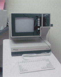
Figure 6-17 A typical ultrasound A/B-scan unit.
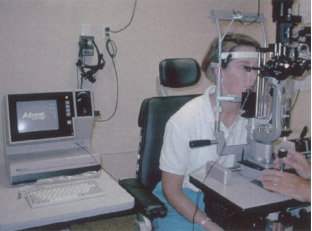
Figure 6-18 An applanation A-scan technique being performed on a patient with mounted probe.
APPLANATION A-SCANS
Indications
- required for measurement of the front surface of the cornea (Fig. 6-18)
- minimization of risk for obtaining artificially short axial length measurements because of corneal indentation during applanation of the corneal surface by using an available spring-loaded mount on the probe
IMMERSION A-SCANS
Indications
- generally better accuracy because of lack of corneal indentation but slightly more complicated to operate than an applanation A-scan because of the need of creating an immersion waterbath over the eye
- possibility of poor echo readings with extra fluid around the eye because the ultrasound waves must travel through more dense media to get to the eye
Methods
- Place a water bath around the eye to avoid direct corneal indentation (Fig. 6-19).
- Take multiple measurements to ensure consistancy.
Figure 6-19 Immersion A-scan technique being performed on a patient by a technician.
B-Scans
Indications
- best for acquisition of axial length data for highly myopic surgical candidates who have macrophthalmic eyes because of posterior staphyloma and the possibility of inaccurate A-scan data
- availability of A-scan capabilities with many late model B-scan units (see Fig. 6-17)
Methods
- Put an electronic mark on the apex of the cornea (possible with most B-scan units).
- For eyes with an axial length of more than 26.5 mm, measure 4.5 mm temporally from the center of the optic nerve and place another electronic mark at that point on the retina for each eye (the center of the optic nerve and the fovea are about 4.5 mm apart).
- The difference between the two electronic marks is the “true” axial length of the eye, the distance between the fovea and the corneal apex instead of the distance between the posterior portion of the staphyloma and the corneal apex.
- Repeat for the other eye.
HIGH-FREQUENCY ANTERIOR SEGMENT ULTRASOUND BIOMICROSCOPY
Indications
- determination of the exact anatomical relationship among the posterior iris and anterior lens capsule, anterior chamber depth, and anterior chamber angle anatomy
- preoperative evaluation for implantation of an intraocular contact lens (ICL) behind the iris and in front of the natural lens to correct myopic or hyperopic refractive error while still allowing for accommodation (STAAR Surgical Co., Monrovia, CA; currently undergoing investigative trials)
Methods
- Cover the closed anesthetized eye with ultrasound gel supplied by the manufacturer of the probe.
- Place the ultrasonic probe over the closed, anesthetized eye.
- Maintain the appropriate angulation of the probe (90 degrees to the surface being examined), which will yield the sharpest image.
CONTRAST SENSITIVITY TESTING
Indications
- evaluation of a patient’s visual function for different levels of contrast
- incorporation of sinusoidal gratings that proceed from low spatial frequency to high spatial frequency going down the chart vertically (most charts)
- variation of contrast of the sinusoidal gratings from high to low, going left to right horizontally across the chart for each spatial frequency (most charts)
- allows examiner to decide if prescription eyeglasses will help the patient’s visual function under certain conditions (e.g., improved driving at night if contrast sensitivity is better with eyeglasses)
- incorporation of sinusoidal gratings that proceed from low spatial frequency to high spatial frequency going down the chart vertically (most charts)
- commercial availability of many different types of contrast sensitivity charts and testing devices [some designed for near, some for distance, and some for both distance and near; some charts with illuminated backgrounds and remote-control devices, and others mounted on cardboard (Fig. 6-20)].
- especially valuable to evaluate impact of eyeglasses on vision if early cataracts or glaucoma are present
- evaluation of postoperative patients who complain of decreased vision in dimly lit conditions
Methods
- Follow the manufacturer’s suggested instructions for use and grading (provided with test).
- Perform distance contrast sensitivity testing 10 feet from the chart.
- Perform near testing usually 18 inches from the chart.
- Perform contrast sensitivity testing near and at distance with and without correction; in dim and bright lighting.
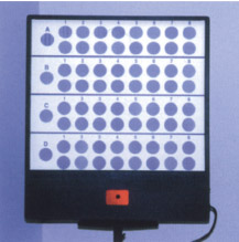
Figure 6-20 A remote-controlled contrast sensitivity chart with background illumination.
Suggested Readings
Assil KK, Schanzlin DJ. Radial and Astigmatic Keratotomy: A Complete Handbook. St. Louis, MO: Poole Press; 1994.
Carlson NS, Kurtz D, Heath DA, Hines C. Clinical Procedures for Ocular Examination. Norwalk, CT: Appleton & Lange; 1990.
Holladay JT. Why the A-scan is your key to better cataract care. Rev Optometry. 1999; 30:85-88.
Machat JJ, Slade SG, Probst LE. The Art of LASIX. 2nd ed. Thorofare, NJ: Slack Inc.; 1999.
< div class='tao-gold-member'>


