Custom Laser In Situ Keratomileusis with Wavefront Technology*
CHAPTER CONTENTS
Current Ocular Evaluation Systems and Laser Correction Methods
CURRENT OCULAR EVALUATION SYSTEMS AND LASER CORRECTION METHODS
Laser refractive procedures currently use only refractive data as the template for refractive programming of the laser. Although corneal topography systems contain descriptive data that could be incorporated into laser programs, early attempts to do so met with limited success. Results with topography-guided laser programs (e.g., Contoured Ablation Program; VISX, Inc. Santa Clara, CA) and topography-guided systems (TopoLink; Bausch 8c Lomb, Rochester, NY) have been limited. Wave-front technology attempts to overcome the limitations of these systems.
Limitations
- phoroptors and autorefractors
- quantification of only sphere, cylinder, and axis of cylinder
- lack of measurement of irregular astigmatism and other higher-order aberrations
- limitation of resolution to 0.12 D
- quantification of only sphere, cylinder, and axis of cylinder
- corneal topography
- extrapolation of height data from slope data by Placido disc or Humphrey topographer (Alcon, Fort Worth, TX) technology (leads to approximations of many of the mapped points)
- true height data obtainable but analysis limited to the cornea with slit-light systems (Orbscan; Orbtek but now Bausch & Lomb, Rochester, NY)
- accuracy of 0.25 D or 2 to 3 μm for corneal curvature and elevation data, respectively
- removal of only ∼ 0.25 μm of tissue per pulse of an excimer laser
- accuracy of 0.25 D or 2 to 3 μm for corneal curvature and elevation data, respectively
*The author thank Greg Halstead, Thomas McKay, and Kevin Tausend of VISX, Inc., for their tecnical support and encouragement regarding this manuscript.
COMMON OCULAR ABERRATIONS
An aberration of a light ray is the deviation of light from the path that is predicted by standard first-order geometric optics. Seidel developed terminology that expresses the aberration of form as five sums, S1 to S5 (Table 12-1). For example, spherical aberration is eliminated when S1 = 0. According to Seidel, no optical system may have all five sums equal to zero or have absolutely no optical aberrations.
Chromatic Aberrations
- A chromatic aberration is a deviation in the differential refraction of the color spectrum, but other aberrations that are unrelated to chromatic aberrations also occur.
- The cornea and crystalline lens each have a different refractive index for every wavelength of light.
- The eye focuses blue light (a short wavelength) in front of red light (a longer wavelength), which results in an imperfect point of focus.
- Chromatic aberration increases with the size of the pupil and increased distance between the light ray and the optical center of the cornea or crystalline lens.
- The sharpest retinal image is produced when the pupil is 2 to 3 mm in diameter.
- Pupils smaller than 2 to 3 mm degrade the sharpness of the retinal image by diffraction effects on the edge of the pupillary aperture.
- The sharpest retinal image is produced when the pupil is 2 to 3 mm in diameter.
Spherical Aberrations
- The converging power of a plus spherical lens increases as the lateral distance from the central ray increases.
- Rays at the edge of the lens are focused anterior to the focus of the central ray.
- No single, sharp point of focus exists for all light rays that pass through the pupil.
- The anterior surface of the cornea and the anterior and posterior surfaces of the crystalline lens cause spherical aberration in the human eye.
- The aberration is proportional to the square of the pupil size.
- The increase in spherical aberration and myopia (0.5-1.0 D) with pupillary dilation cause night myopia.
Oblique Aberrations
- These aberrations are identified after the correction of other types of aberrations (when off-axis light rays are less distinct than the light rays on the visual axis).
- Oblique aberrations are difficult to define and measure.
COMA Coma is similar to spherical aberration but applies to off-axis light rays, which are distributed over a small area of the image rather than converging at a single point.
- The distribution of light rays resembles a comet.
- Coma is proportional to the square of the pupillary aperture and increases as the object moves away from the optical axis.
| Classification | Aberration | Seidel’s Sum |
|---|---|---|
| Spherical aberration | Spherical aberration | S1 |
| Oblique aberrations | Coma | S2 |
| Radial astigmatism | S3 | |
| Curvature of field | S4 | |
| Distortion | S5 |
RADIAL ASTIGMATISM AND CURVATURE OF FIELD Radial astigmatism is also known as oblique astigmatism, marginal astigmatism, or astigmatism of oblique incidence.
- This property of all simple lenses is observed after removal of the spherical aberration and coma.
- A point off-axis is imaged as two lines at right angles to each other, each perpendicular to the chief (central) light ray.
- A multitude of points in a plane that are affected by radial astigmatism create curvature of field.
- Radial astigmatism and curvature of field negate each other when radial astigmatism equals curvature of field.
DISTORTION Inconsistent lateral magnification over the field of view leads to distortion.
- A pinhole camera is free of distortion because it has only central light rays.
- “Pincushion-” and “barrel-” shaped distortions (experienced when looking through a high-power lens) may result from distortion, depending on the configuration of the optical system.
Point-Spread-Function
- Diffraction occurs along the margin of the pupil.
- Limitations of the pupillary aperture cause light to spread, even in a perfectly focused system.
- The Fraunhofer diffraction image of a point object through a circular aperture has a bell-shaped distribution with oscillating fringes.
- The center portion of the pupillary diffraction pattern is a small circle called the Airy’s disc.
Higher-Order Aberrations
- Wavefront technology identifies higher-order aberrations.
- These aberrations are then classified according to their Zernike order (up to the tenth order).
- Thibos and Hong (1999) have shown an increase in higher-order aberrations, specifically spherical aberrations, after myopic laser in situ keratomileusis (LASIK; Fig. 12-1).
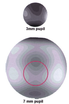
Pupil Size and Optical Aberrations
- Image quality does not increase with pupils smaller than 2.5 mm because of diffraction effects from the pupil.
- Ocular aberrations increase as the pupil dilates, approximately offsetting the diffraction effects of a smaller pupil.
- With pupils larger than 5.0 mm, light spread increases because of greater aberrations present in the peripheral cornea and the increased amount of light that enters the eye from the peripheral area.
WAVEFRONT TECHNOLOGY
In the mid-1970s, Dr. Josef Bille, director of the Institute of Applied Physics at the University of Heidelberg, developed techniques to correct imperfect higher-order aberrations (or wavefront distortions)that entered telescopic lens systems from space. These techniques of wavefront technology used “adaptive optics,” deformable mirrors were used to reform the distorted wavefront to allow clear visualization of celestial objects. According to Bille, 99.9% of the population undergoing refractive surgery have retinas that are capable of seeing 20/10, but the shape of their corneasdoes not permit such clear vision. Bille obtained the first German patents for wavefront technology in 1982 and 1986. In 1997, Bille cofounded 20/10 Perfect Vision, which designed and marketed a stand-alone desktop-sized testing device that includes an image acquisition device, monitor, computer processing unit, and keyboard.
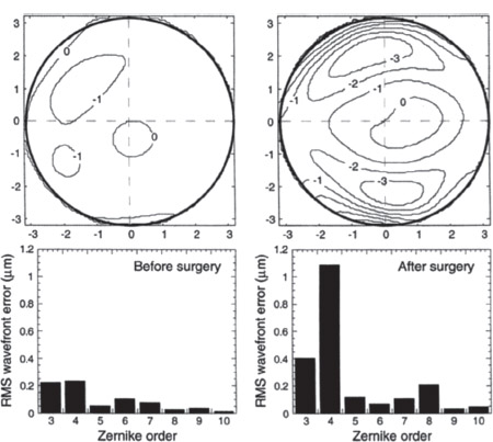
Figure 12-1 Normal eye the day before and the day after myopic LASIK. [upper row) Aberrations as related to the pupil, (lower row) The distribution of wavefront error by Zernike order. To emphasize the change in higher-order aberrations, residual spherocylindrical refractive errors were omitted from the analysis. The Zernike polynomial aberration of the first order is spherical error, the second order is regular astigmatism, the third order is coma, and the fourth order is spherical aberration. Other aberrations are measured up to the tenth order. Note the significant increase of third-and fourth-order aberrations along with the increase in fifth to tenth orders. (Courtesy of American Academy of Optometry. Thibos LN, Hong X. Clinical applications of the Shack-Hartmann Aberrometer. Optom Vis Sci 1999;76:817-825.)
The Shack-Hartmann Wavefront Analysis System
Wavefront analysis completely evaluates the entire optical system instead of limiting analysis to the confines of subjective or objective refraction and corneal topography. By measuring all optical aberrations of the ocular system, wavefront analysis potentially allows correction of these ocular aberrations.
Methods
- The system projects wavelengths of light as flat sheets or “wavefronts” into the eye, onto the macula, and through the entire optical system and then reflects the wavelengths back through the cornea.
- A charge couple device (CCD) video camera collects images within the acquisition module.
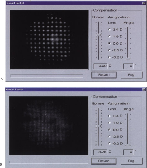
- In an optical system without aberration, the wavefront exits the eye as the same parallel flat sheets that entered the eye (Figs. 12-2A and Figs. 12-3A).
- In an optical system with aberrations, the flat sheets that entered the eye exit as irregular curved sheets (see Figs. 12-2B and Figs. 12-3B).
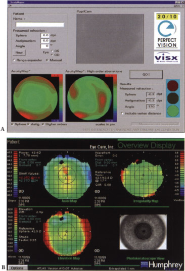
- The CCD video camera captures the returning wavefront and converts it to a color-coded acuity map (phase map or spatially resolved refractometer map) for points over the pupil area (Fig. 12-4).
- The map is a translation of 100,000 data-point measurements taken every 20 μm over a 6-mm pupil.
- The Shack-Hartmann data map demonstrates the raw light image that impinges on the CCD camera and demonstrates all the optical aberrations (Fig. 12-5).
- The map is a translation of 100,000 data-point measurements taken every 20 μm over a 6-mm pupil.
- The technician obtains subjective patient feedback to determine potential uncorrected visual acuity (UCVA) by projecting an acuity chart similar to Snellen’s onto the patient’s fovea after application of the adaptive optics.
Limitations
- wavefront analysis
- Tear-film abnormalities may significantly affect the quality of wavefront analysis.
- Current Shack-Hartmann devices poorly define opacities because of the inability of the source testing light to reach the retina and reflect back to the CCD video camera.
- Marked aberrations for corneal scars or keratoconus are very difficult to measure.
- Miotic pupils are difficult to measure, may require pharmaceutical dilation, and provide data that do not represent the wavefront of the entire eye (Fig. 12-6).
- Wavefront-sensing technology currently does not define the exact location of the pathology that is causing the aberration.
- Techniques to create the “perfectly adapted optic” with spectacle correction or corneal or implant surgery to neutralize the pre-existing abnormal wavefront must be refined.
- Tear-film abnormalities may significantly affect the quality of wavefront analysis.
- retinal limitations for adaptive optics
- Clinical or subclinical amblyopia may limit visual potential.
- Some maculas may not have sufficient cone density to support 20/10 vision.
- The directional sensitivity of the retinal cone receptors (Stiles-Crawford effect) limits the effect of light rays that do not enter the eye through the pupillary aperture.
- Clinical or subclinical amblyopia may limit visual potential.
- Retinal pathology or irregularities in high myopia or posterior staphylomas may limit the best vision possible.
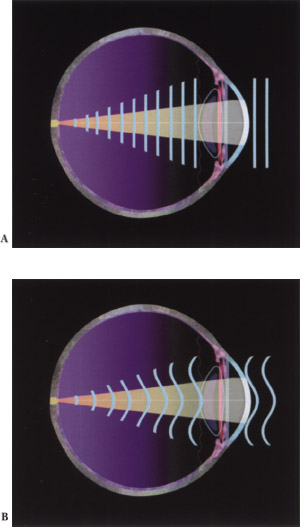
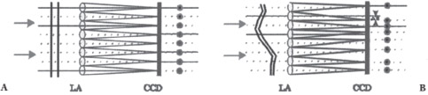
Figure 12-3 (A) Incident plane wave resulting in a square grid of spots. (B) A distorted wavefront causes lateral displacement of spots.
Wavefront Systems for Refractive Surgery
THE 20/10 PERFECT VISION SYSTEM The first treatments using this Shack-Hartmann-style wavefront device were performed in the United States in early 2000. The system should be potentially commercially available in 2001.
- This system describes the refraction of the eye within 0.05 μm (five times more accurate than the excimer laser beam and approximately 25-50 times more accurate than phoropter-, autorefractor-, and topography-based systems)
- The device works with the VISX STAR laser as the VISX WaveScan Wavefront System.
CUSTOM CORNEA MEASUREMENT DEVICE This Shack-Hartmann-style wavefront device may be commercially available in 2001 or 2002.
- This device is used with the LADARVision laser (Summit Technologies).
- All patients (5 of 5) achieved 20/16 to 20/32 vision in a 2000 U.S. Food and Drug Administration trial.
THE DRESDEN WAVEFRONT ANALYZER This analyzer is based on the Tschernig aberroscope, which was first described in 1894. A bundle of equidistant light rays are projected though the cornea, and an indirect ophthalmoscope measures deviation from the ideal pattern of all spots and directs the image” to a low-light CCD linked to a computer. Dr. Theo Seiler and colleagues (University Eye Clinic, Dresden, Germany) developed the analyzer, and it is distributed by Technomed GmbH (Baesweiler, Germany) but will not be commercially available until 2001 or 2002.
- The Dresden analyzer evaluates the retinal image instead of outgoing light (unlike the Shack-Hartmann device).
- Use the analyzer with the Wavelight (Erlangen, Germany) Allegretto scanning-spot laser and scanning-spot laser from Schwind Eye-Tech-Solutions GmbH (Kleinostheim, Germany).
- Wavefront aberrations in the form of Zernike polynomials are computed from this data, which are integrated with preoperative corneal topography.
- An aberration-free ablation profile is calculated.
- The precision of the device allows for an objective measurement of spherical and cylindrical refractive error with an accuracy of better than ±0.25 D.
- The first three patients who were studied achieved uncorrected visual acuity between 20/12.5 and 20/10.
THE ABERROMETER/WAVEFRONT ANALYZER This Shack-Hartmann-type wave-front system was designed by Technolas GmbH (Munich, Germany).
- Use this analyzer in conjunction with the Orbscan topography device (Orbtek, now Bausch 6c Lomb, Salt Lake City, UT).
- Use with the Bausch 8c Lomb Surgical (Claremont, CA) 217 laser (the 217Z system for wavefront-guided LASIK, known as Zyoptix is currently available in Canada, Italy, and Germany)
- The Orbscan 3D corneal analyzer is linked to the ZyWave wavefront analyzer to provide maximum optical data.
- Most of the 200 eyes that have been treated at TLC The Laser Eye Center (Toronto) achieve better than 20/20 UCVA.
ELECTRO-OPTICAL RAY-TRACING ANALYZER Tracy Technologies (Bellaire, TX) manufactures this analyzer, which uses the fundamental thin-beam principle of optical ray tracing to measure the refractive power of the eye on a point-by-point basis. No adaptive optics have been developed presently.
- This analyzer measures one point at a time at the entrance pupil rather than the entire entrance pupil at once (unlike the aberroscopes and Shack-Hartmann device) to avoid the possibility of data points crisscrossing with highly aberrated eyes.
- Semiconductor photodetectors detect the location where each light ray strikes the retina and calculates the difference from the ideal conjugate focus point, giving direct measurement of refractive error for that point in the entrance pupil.
SPATIALLY RESOLVED REFRACTOMETER This analyzer is currently being designed, built, and tested by the Emory Vision Correction Center at Emory University (Atlanta, GA).
- Tests are completed in a relatively lengthy 3 to 4 min.
- Patients are directly involved in the testing (adds important subjective value).
EYE TRACKING
To achieve the maximum benefit from wavefront-derived custom LASIK, we must track the position of the eye so that the correct location is ablated. Any deviation from this exact position may lead to a significant decline in postoperative UCVA. Eye trackers that are currently available have several limitations that need to be addressed before the trackers are used successfully with custom LASIK.
Limitations
- The Bausch and Lomb 217 eye tracker has a relatively slow reaction time.
- The LaserSight LSX tracker may require the patient to maintain difficult head positions to get the tracker to work.
- Intermittent tracker activation delays the procedure, potentially leading to stromal dehydration and overcorrection.
- The Autonomous Technologies tracker (now manufactured by Summit Technologies) requires pupillary dilation and predilation photographs that are time-consuming and cumbersome to obtain.
Suggested Readings
Dougherty PJ, Wellish KL, Maloney RK. Excimer laser ablation rate and corneal hydration. Am J Ophthalmol. 1994;118:169-176.
Liang J, Grimm B, Goelz S, Bille JF. Objective measurement of wave aberrations of the human eye with the use of a Hartmann-Shack wave-front sensor J Opt SocAm A. 1994;11:1949-1957
Oshika T, Klyce SD, Applegate RA, Howland HC, El Danasoury MA. Comparison of corneal wavefront aberrations after photorefractive keratectomy and laser in situ keratomileusis. Am] Ophthalmol 1999;127:1-7.
Thibos LN, Hong X. Clinical applications of the Shack-Hartmann Aberrometer. Optom Vis Sci. 1999;76:817-825.
Webb R, Penny CM, Thompson K. Measurement of ocular local wavefront distortion with a spatially resolved refractometer. Appl Opt. 1992;31:3678-3686.
< div class='tao-gold-member'>


