Wavefront-Guided Custom Lasik and Lasek: Techniques and Outcomes
Patrick C. Yeh
Dimitri T. Azar
The efficacy, predictability, and safety of using the excimer laser in the correction of refractive errors have been widely demonstrated and accepted (1, 2, 3, 4). Optical engineers, physicists, and refractive surgeons continue to refine surgical techniques and break new ground in laser vision correction using novel technologies and new applications of previous innovations. Chief among them is the exponential progress in the fields of wavefront-guided and topography-guided custom corneal ablation, with the ultimate aim of sculpting an optically perfect eye in which the unaided postoperative visual acuity exceeds the preoperative spectacle corrected visual acuity.
The desire to eliminate optical aberrations has led to great interest in the pursuit of ocular wavefront-sensing and the coupling of the sensors to lasers to create wavefront-guided ablations. In contrast to corneal topography, which measures only the aberrations created by the corneal surface, wavefront sensing measures the aberrations of the entire optical system of the eye, including those resulting from the anterior surface of the cornea, as well as additional aberrations emanating from the posterior corneal surface and the lens.
The current status of custom cornea treatment is improvement of the quality of the image of a point object, or the point spread function (PSF) on the retina, primarily by reducing preexisting wavefront aberrations (5). As our understanding of the more visually significant surgically induced aberrations continues to increase, we may soon be able to correct them to achieve the so-called supervision with greater predictability.
In the 20th century, eye care professionals were able to reduce refractive errors with spectacles, contact lenses, intraocular lenses, and various refractive surgeries by successfully correcting the sphere and cylinder, which are lower-order aberrations (defocus and astigmatism, respectively). It was not until recently that we have the means of measuring and treating higher-order aberrations in a clinical setting. Other optical phenomena, such as the unavoidable effects of pupil-dependent diffraction that may limit sharpness of retinal images, become the remaining optical limiting factors (6). Quantification of these phenomena may soon lead to development of newer diagnostic and therapeutic tools in the field of refractive surgery.
One obvious advantage of correcting the optical aberrations in the eye is the potential for creating an optically perfect retinal image. However, the complexity of the visual system, including the optics, photoreceptors, neuronal processing of visual signals, and the formation of the visual percept, creates upper limits to supernormal vision.
The visual acuity is limited by receptor diameter, receptor packing, as well as biologic variations. The neural retina does not have a uniform distribution of cones. The foveola has the highest packing density of cones and the highest spatial resolving capacity, and as such it is the area that provides the sharpest central vision. Cone density and spatial resolving ability decrease as the distance from the foveola increases. Within the foveola, the diameter of the cone photoreceptors also limits the retina’s ability to sample the retinal image. For instance, if the eye’s optics are corrected to such a degree as to allow the image of the letter “E” to fall on a single cone, the visual system cannot differentiate the “E” from a period (Fig. 81-1). This is an example of neuronal undersampling, which results in a phenomenon known as “aliasing” (5). For proper interpretation, the components of “E” must be imaged over a certain number of photoreceptors. Given the spacing of foveal cones, which is about 2 to 3 μm, the best achievable acuity for the normal eye is estimated to be 20/8 and 20/10 (75 cycle/degree and 60 cycle/degree), depending on pupil size (7,8). Furthermore, neural processing of visual signals and the formation of the visual percept may add more limitations to achieving perfect and useful vision. A perfect and useful vision requires proper functioning at all levels of this intricate visual system. The visual cortex cannot form a useful visual percept without a good retinal image. Likewise, an optically perfect retinal image cannot be turned into a useful vision without the capability of interpreting the image in proper context. Nonetheless, despite these well-known
inherent challenges and limitations in pursuing superior clinical outcomes with customized corrections, removing higher-order aberrations in addition to defocus and astigmatism have been shown to improve retinal image contrast at each spatial frequency, resulting in better visual quality (9).
inherent challenges and limitations in pursuing superior clinical outcomes with customized corrections, removing higher-order aberrations in addition to defocus and astigmatism have been shown to improve retinal image contrast at each spatial frequency, resulting in better visual quality (9).
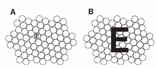 FIGURE 81-1. A, If the letter “E” falls within a single photoreceptor, then the visual system cannot differentiate the “E” from a period. B, The letter “E” must be sampled by enough photoreceptors to differentiate the letter’s component parts. (From Applegate RA. Limits to vision: can we do better than nature? J Refract Surg 2000;16(suppl):S548, with permission.) |
HISTORY, PRINCIPLES, AND METHODS OF WAVEFRONT ANALYSIS
Original applications of wavefront technology appeared as early as 1619, when Scheiner, a philosopher-astronomer, developed the Scheiner disk perforated with two pinholes to demonstrate the focusing ability of the human eye. Double retinal images of a single object are formed when an ametropic eye views through the Scheiner disc (10). Beginning with the development of an “aberroscope” by Tscherning (11) in 1894 wave aberration could be evaluated via a subjective method for the first time. Its principle was expanded by Hartmann and resulted in the development of Hartmann’s wavefront sensor in 1900. Shack and Platt (12) in 1971 published the first work related to the foundation of wavefront technology and made modifications to the Hartmann’s wavefront sensor. The result was known as the Hartmann-Shack aberrometer. By 1976 the principle of adaptive optics based on the Hartmann-Shack wavefront sensor was widely utilized in the field of astrophysics to enhance the images through ground-based telescope. In 1994 this technology was first adapted successfully to clinical ophthalmology by Liang et al. (13,14) in the measurement of the eye’s wave aberration. In 1997 the technology was furthered in its application to allow accurate removal of those aberrations using a deformable mirror, or adaptive optics. As a result, high-resolution and noninvasive retinal imaging of microscopic structures the size of single photoreceptors in a living human retina was made possible for the first time (15,16). These experiments moved the center stage of wavefront sensing from astronomy to refractive surgery. Wavefront sensing has recently expanded its horizon of applications and permeated to other areas of interests and studies in ophthalmology, such as wavefront-aided intraocular lens (IOL) design to reduce chromatic aberrations and improve contrast sensitivity (17).
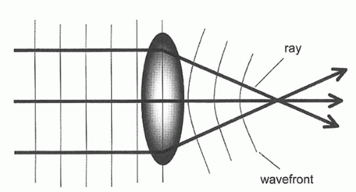 FIGURE 81-2. Optical system and wavefront. A wavefront is always perpendicular to the direction of the light rays. (From Maeda N. Wavefront technology in ophthalmology. Curr Opin Ophthalmol 2001;12:295, with permission.) |
What is a wavefront? In physical optics, light is considered as a wave that spreads in all directions; a wavefront is like a ripple that is in phase when a stone is thrown into a still pond. A wavefront describes light rays emanating from a source and represents an isochronous surface shape, that is, all the points along the rays that are in-phase (18) (Fig. 81-2). It measures the optical path in its entirety and is not limited to any given refractive surface. Thus, the wavefront describes the aggregate effects of the optical system of the whole eye as the light passes through every location of the pupil. In a “perfect” eye, the optical system of the eye does not induce any distortions in the wavefront from the image. The wavefront would exit the eye as a perfect plane that is perpendicular to the visual axis. On the other hand, when optical aberrations are present, as it is in all eyes (even in unoperated eyes), the wavefront would form an imperfect surface rather than a plane. Wavefront aberrations are defined as the deviation between the wavefront surface originating from a given optical system and the hypothetical wavefront plane originating from an ideal optical system. For a given eye, the shape of the wavefront is a fundamental and unique description of the optical quality of the whole eye (Fig. 81-3).
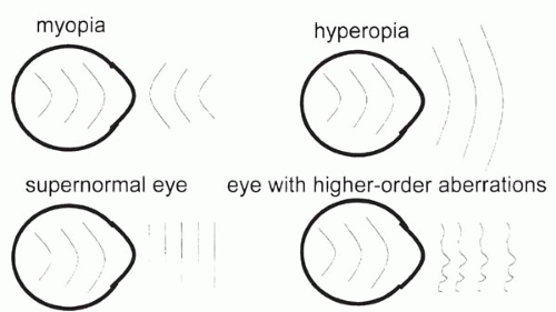 FIGURE 81-3. Schematic representation of refractive errors diagrams using wavefront. (From Maeda N. Wavefront technology in ophthalmology. Curr Opin Ophthalmol 2001;12:295, with permission.) |
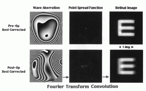 FIGURE 81-4. The retinal image can be simulated by computing the point-spread function. (From Applegate RA, Azar DT, Klyce SD, et al. Corneal topography vs. wavefront sensing. Rev Refract Surg 2002;10, with permission.) |
Wavefront analysis assesses the optical quality of the eye by evaluating the shape of its wavefront. It expresses the deformity of wavefront shape in three-dimensional space. The unit used in wavefront analysis is micrometers or fractions of wavelengths, and is often displayed as the root mean square (RMS). Alternatively, the influence of aberration on retinal image quality can be simulated by computing the point-spread function (PSF) using the standard Fourier optics methods (Fig. 81-4).
Wavefront aberrations are usually expressed mathematically in polynomial expansions (18). In the first half of the last century, Zernike developed a set of polynomial equations and applied them for the analysis of wavefront properties of optical systems (19). Zernike decomposition breaks the wave aberration into its component aberrations. A multitude of optical aberrations exist and are usually grouped into two major categories: lower order and higher order aberrations. There are three components to the lower order aberration: zero order (a constant), first order (tilt or prism), and second order (defocus and astigmatism). Lower order aberrations can be corrected with glasses, contact lenses, and conventional laser surgery. Higher order aberrations are simply fit to a more complex wavefront shape. They represent smaller irregularities in the optical system of the eyes, representing about 17% of the total optical error in humans. Some of the more common higher order aberrations include third order (coma and trefoil), fourth order (spherical aberration and secondary astigmatism), fifth order (secondary coma), and sixth order (secondary spherical aberration) (Fig. 81-5). Polynomials can be expanded up to any arbitrary order if sufficient numbers of measurements for calculations are made. Using the Zernike coefficients of each term, monochromatic aberrations can be evaluated quantitatively. The understanding of the clinical significance of many of the higher order aberrations is still at its infantile stage. Although it has been recognized that spherical aberration and coma can result in reduced quality of vision, the effect of other higher aberrations is less well understood (9,14,19).
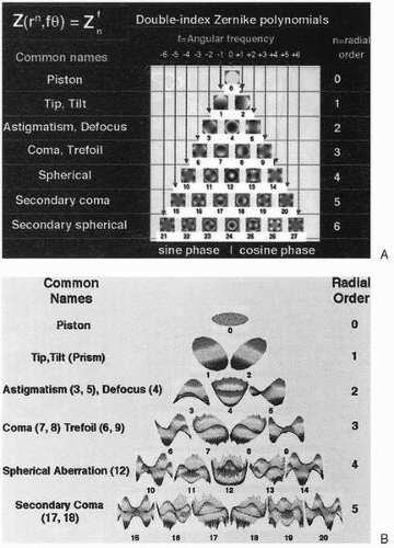 FIGURE 81-5. A, Two-dimensional pictorial representation of some of the Zernike polynomials. B, Three-dimensional pictorial representation. (From Wavefront sensors: the shape of things to come. Rev Refract Surg August 2001;14, with permission.)(see color image) |
Despite differences in their operating principles, wavefront analyzers usually use ray-tracing methods to trace the path of multiple light rays through the individual eye to reconstruct the wavefront. In general, the wavefront sensors can be classified into three types: (1) in-going retinal imaging aberrometry, as in Tscherning and sequential retinal ray tracing method; (2) out-going wavefront aberrometry, as is used in the Hartmann-Shack aberrometer; and (3) in-going feedback aberrometry, as in skiascopy and spatially resolved refractometer.
Tscherning Aberrometry
Tscherning aberrometry can be traced back to 1890s when Tscherning (11) devised a subjective method of evaluating optical aberrations of the human eyes. More recently, this initially subjective method was converted into an objective means for measuring the optical aberrations. A collimated laser beam [frequency doubled neodymium:yttrium-aluminum-garnet (Nd:YAG) laser,
wavelength 532 nm] was used to illuminate a mask with regular matrix pin holes creating 168 single light rays. These rays form a retinal spot grid pattern on the retina. By indirect ophthalmoscopy, a low-light charge-coupled-device (CCD) camera was used to detect the distortion on the retinal (Fig. 81-6). The aberrations were calculated based on the deviations from their ideal regular positions. The optical aberrations were computed from these values in the form of Zernike polynomials up to the eighth order (20). The wavefront diagnostic devices that utilize Tscherning’s aberroscope include Allegretto Wavefront Analyzer (Wavelight) and ORK Wavefront Aberrometer (Schwind).
wavelength 532 nm] was used to illuminate a mask with regular matrix pin holes creating 168 single light rays. These rays form a retinal spot grid pattern on the retina. By indirect ophthalmoscopy, a low-light charge-coupled-device (CCD) camera was used to detect the distortion on the retinal (Fig. 81-6). The aberrations were calculated based on the deviations from their ideal regular positions. The optical aberrations were computed from these values in the form of Zernike polynomials up to the eighth order (20). The wavefront diagnostic devices that utilize Tscherning’s aberroscope include Allegretto Wavefront Analyzer (Wavelight) and ORK Wavefront Aberrometer (Schwind).
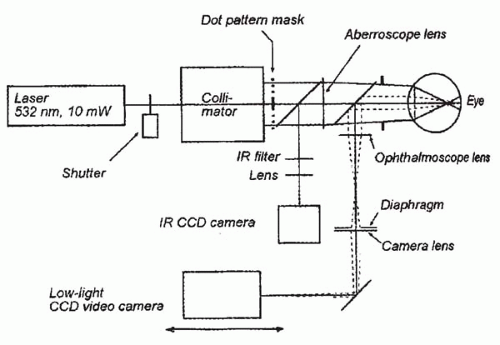 FIGURE 81-6. Schematic diagram of wavefront sensor based on the principles of Tscherning aberrometry. (From Mrochen M, Kaemmerer M, Mierdel P, et al. Principles of Tscherning aberrometry. J Refract Surg 2000;16(suppl):S570, with permission.) |
Sequential Ray Tracing Aberrometry
Ray tracing aberrometry uses measurement of the position of a thin laser beam (0.3 mm in diameter) projected onto the retina. The beam is directed into the eye parallel to the visual axis through various points of the pupil. To compensate for saccadic eye movements during measurement, the scanning is performed within 10 to 20 msec. The measured location of each ray as it exits the eye is calculated against the known position, and the wave aberration function is described by Zernike polynomials (21). The Tracey Technology wavefront device is based on ray tracing aberrometry (Fig. 81-7).
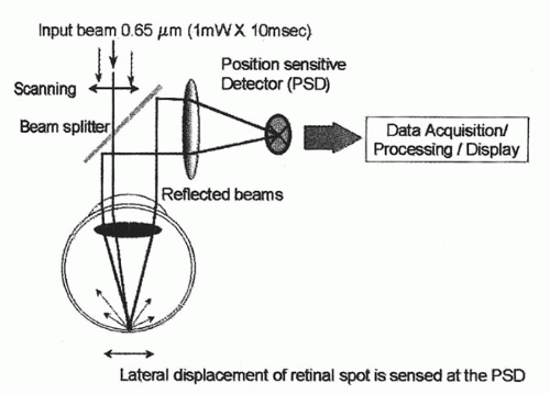 FIGURE 81-7. Schematic diagram of Tracey. (From Clinical experience with the Tracey technology wavefront device. J Refract Surg 2000;16:S589, with permission). |
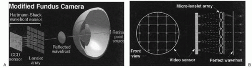 FIGURE 81-8. Hartmann-Shack aberrometer. A, The wavefront of the reflected retinal point source is sampled by an array of small lenses (the lenslets) in the aberrometer. B, The displacement of each spot from its calibrated position is a direct measure of the slope of the wavefront over the lenslet that formed a particular spot. (From Thibos LN. Principles of Hartmann-Shack aberrometry. J Refract Surg 2000;16(suppl);S564, with permission.) |
Hartmann-Shack Aberrometry
A Hartmann-Shack aberrometer projects a laser light into the eye to illuminate a small spot on the retina. The probe light reflected from the fovea is imaged onto the Hartmann-Shack sensor, which consists of a matrix of small lenslets. These lenslets sample corresponding areas of the pupils and divide the wavefront into individual beams, producing multiple images of the same retinal spot of light to form a spot pattern that is focused onto a CCD camera. The deviation of each spot from its corresponding lenslet axis is used to calculate the aberrations (Fig. 81-8).
Mathematical integration of the deviation yields the shape of the aberrated wavefront, expressed in terms of Zernike polynomials (10). Wavefront devices that utilize the Hartmann-Shack technology include LADARWave (Alcon) (Fig. 81-9), WaveScan WaveFront (VISX) (Fig. 81-10), ZyWave (Bausch & Lomb), WASCA Wavefront Aberrometer (Asclepion-Meditec), and Quantum Light Wavefront Analyzer (Zeiss Humphrey Systems).
Mathematical integration of the deviation yields the shape of the aberrated wavefront, expressed in terms of Zernike polynomials (10). Wavefront devices that utilize the Hartmann-Shack technology include LADARWave (Alcon) (Fig. 81-9), WaveScan WaveFront (VISX) (Fig. 81-10), ZyWave (Bausch & Lomb), WASCA Wavefront Aberrometer (Asclepion-Meditec), and Quantum Light Wavefront Analyzer (Zeiss Humphrey Systems).
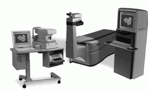 FIGURE 81-9. The LADARWave wavefront measuring device. |
Dynamic Skiascopy
Using the principle of retinoscopy, skiascopy optical path detection projects a moving slit into the eye. The projecting system consists of an infrared light-emitting diode (LED) that emits light going through a chopper wheel with slit apertures, which is located between the LED and the projecting lens. The wheel rotates constantly at high speed (180 degrees in 0.4 second across both hemimeridians) to scan the retina. The slit light rays are reflected back out of the eye through a receiving lens, an aperture stop, and photo detectors that receive the light signals. The relative motion of the slit’s image is used to calculate the refractive error along each segment (22) (Fig. 81-11). The wavefront system based on skiascopy includes the OPD-scan (Nidek).
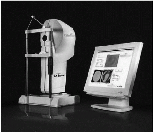 FIGURE 81-10. The WaveScan WaveFront System. |
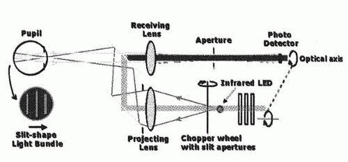 FIGURE 81-11. Schematic diagram of wavefront sensor based on the principles of dynamic skioscopy. (From MacRae SM, Fujeida M. Slit skiascopic-guided ablation using the Nidek laser. J Refract Surg, 2000;16:S576, with permission.)
Stay updated, free articles. Join our Telegram channel
Full access? Get Clinical Tree
 Get Clinical Tree app for offline access

|