Video-Based Low-Vision Devices
Jennie Y. Kageyama
Joseph L. Demer
Steven D. Schwartz
Melissa W. Chun
Low-vision devices, whether optical or video based, facilitate visual function and mitigate limitations due to visual impairment.1,2 Visual impairment can result from three forms of loss: loss of central acuity, which represents resolution; loss of sensitivity to contrast; and loss of visual field. Visual impairment defined strictly on the basis of central acuity can be categorized as moderate (20/70 to 20/160), severe (20/200 to 20/400), or profound (worse than 20/400). The most commonly used visual aids address the problem of reduced visual acuity and use magnification to increase image size on the retina to compensate for the patient’s limited visual resolution. However, optical magnifiers, such as loupes, telescopes, and convex lenses, achieve image enlargement at the expense of other image characteristics that may be crucial for patients with low vision, namely: image brightness, contrast, and useful visual field. All these factors contribute to the impediment for quality viewing.
In distinction to optical magnifiers, video-based image processing systems need not sacrifice other image properties to achieve magnification. Although beneficial for patients with various degrees of visual deficits, video-based devices are particularly useful for patients with severe to profound visual impairment when conventional low-vision devices are determined to be inadequate. Fonda et al.3 found that the closed-circuit television (CCTV) or electronic vision enhancement system (EVES) was most appropriate when optical devices did not produce sufficient magnification. Video-based systems introduced major advantages for people with low vision. These advantages include higher levels of magnification without brightness loss inherent in purely optical systems, the ability to manipulate the video output electronically to create an enhanced image with greater contrast and increased visual comfort, and the availability of a larger field of view than is possible with solely conventional solutions.4 In fact, the CCTV can electronically magnify up to 60× without significant optical aberration. In addition, binocularity is maintained and the posture to read the text on the screen is more natural than the often uncomfortable and specific positioning required by other high-power, near-vision aids.5 Previously, the primary disadvantage of the CCTV was that the system lacked portability. However, with the availability of new technology in recent years, including the use of both the head-mounted systems and compact, battery-operated handheld devices, this limitation can also be overcome. Furthermore, the availability of smaller and more portable CCTV systems have made them an attractive and more commonly prescribed reading device.
First suggested in 1959 by Potts et al.,6 the use of CCTV systems as a low-vision aid was technologically feasible and popularized in the early 1970s4 by groups such as Genensky7 and Fonda et al.3 Although CCTVs have always been useful for some low-vision applications, recent advances in our understanding of visual physiology, as well as in image processing technology, have greatly expanded the potential value of video-based, low-vision devices. In this chapter, both CCTV technology and the emerging technology of video enhancement are presented, along with an introduction to the various video-based, low-vision devices currently available for the patient with low vision. Optimal reading characteristics are also discussed.
Closed-Circuit Television
A CCTV or EVES system consists of a camera, an X-Y positioning platform under the camera for placement of the text to be scanned, a light source to illuminate the material, and a video display monitor.3,8 The CCTV user moves the camera or printed text systematically to scan from left to right and from top to bottom. The X-Y positioning platform was a significant innovation in the design of CCTV systems because it greatly enhanced the comfort of reading and writing. Magnification is achieved through use of a zoom lens on the camera, the large size of the video monitor screen, digital image enlargement, and reduction of the viewing distance from the patient to the screen. An effective magnification of even 140× is possible,3 although the average magnification most commonly used is far less.9 Basically, two types of magnification are in operation with the use of the CCTV: projection magnification and relative distance magnification.5
Several approaches can be taken to calculate the magnification achieved by a CCTV.10 Total magnification (M) of the CCTV can be calculated from the product of projection magnification (X) and relative distance magnification (Y), M = (X)(Y). Projection magnification X is defined as the print size on the monitor divided by the actual print size of the text (maintaining the same units of measure, e.g., centimeters). Relative distance magnification Y is the reference distance (25 or 40 cm) divided by the working distance in centimeters. Of course, if the reference distance is not designated, it is virtually impossible to determine the total magnification of the system. A cleaner approach in assessing the exact CCTV magnification is to determine the equivalent power provided by such a system. This allows the practitioner to obtain the dioptric equivalent of the projection magnification–relative distance magnification interaction. Once the dioptric equivalent is obtained, it is then easy to compare across systems and select visual aides of equivalent powers for patient evaluation, such as handheld and stand magnifiers, microscopes, or telemicroscopes. Equivalent dioptric power, Deq, equals (X)(Z), where X is the print size on the monitor divided by the actual print size and Z is equal to the dioptric equivalent of the working distance, that is, the reciprocal of the working distance or viewing distance of the patient from the monitor (100/working distance in centimeters). Finally, a quick estimate can be obtained of the amount of projection magnification, which does not depend on working distance. A piece of graph paper is placed under the camera of the CCTV after the appropriate print size has been established on the screen for the individual patient’s reading needs. Another piece of graph paper is then held up to the monitor, and the regular-size graph squares that fit into the length of one or two magnified graph squares on the screen are counted. By dividing the resultant smaller number into the larger number, the projection magnification can be grossly determined.10
Stand-mounted CCTV systems are commonly configured with television receivers, video monitors, or computer monitors. They can be adjusted to provide variably high-contrast, gray-scale, inverse, and various color mode video displays that are most comfortable to the individual patient. The characteristics of enhancement may need to be modified based on the spatial frequency content of the television picture and the progression of the user’s ocular condition.5
Contrast polarities are shown in Figure 46A.1, whereas different contrast intensities are shown in Figure 46A.2. Video displays can achieve contrast of up to 96%.11 Because video image contrast is electronically controllable at any levels below the maximal achievable level in a given device, all video displays can be easily adjusted to produce any desired level of contrast intensity. This means that display contrast usually can be set to exceed that of the original subject matter before the camera. More importantly, contrast polarity can be easily reversed by an inverting amplifier, usually incorporated in video cameras, better-quality monitors, and most computer displays. These features of contrast enhancement and polarity reversal are unique to video-based visual devices.
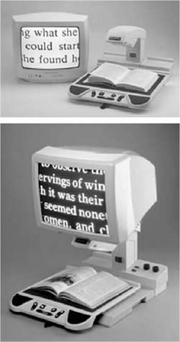 Figure 1. Text in black-on-white contrast polarity on Optelec CCTV (top), and text in white-on-black contrast polarity (bottom). The white-on-black polarity is more readable by patients with low vision who have cloudy ocular media or increased sensitivity to glare. (Photo courtesy of Optelec, Vista, CA.) |
 Figure 46A.2. Words printed with different intensities of contrast: fortune at 90%, tearful at 30%, working at 10%, and visible at 3%. These values have been degraded somewhat by photographic reproduction. (From Legge GE, Rubin GS, Luebker A: Psychophysics of reading: V. The role of contrast in normal vision. Vis Res 27:1165, 1987, with permission.) |
Handheld systems typically consist of a camera and a control box with a cable connected to a television or video monitor. The user holds the camera and moves it across a page, which often requires sufficient hand–eye coordination. Contrast intensity and polarity can also be controlled on these systems.
The new generation of handheld devices incorporates a rechargeable battery and a compact screen to eliminate the need for separate television or video monitors, allowing ultimate transportability and ease of use.
Studies have confirmed the overall effectiveness of CCTVs in improving the reading ability of individuals with all levels of visual impairment.12 Sloan,13 in a case report on CCTVs, identified the following advantages of such a system:
Viewing the screen from a normal reading distance enables people with binocular vision to avoid excessive convergence demand.
Zoom lens allows for rapid change in magnification.
Reversal of contrast to a black background and a white foreground is often less fatiguing than a white background and a black foreground because of the decrease in glare.
CCTV can be used for handwriting.
Higher levels of magnification are available than is possible with purely optical solutions.
Use of an X-Y table is beneficial for persons with visual restrictions who have difficulty keeping their place when reading.
A common theme stressed in the literature and by practitioners is that the effective use of CCTVs is seldom achieved through mere trial and error; rather, both a comprehensive low-vision examination and training in use of the system are critical for success.
The digital revolution has begun to change the design of CCTVs and will continue to do so at an accelerated pace. Digital image processing, now widely and inexpensively available using digital video cameras and personal computers, offers increasing flexibility and ease of use. Images can be enhanced and modified in a multitude of ways, and systems can be endowed with more memory and storage capabilities. These devices are becoming increasingly popular.4
Optimal Image Characteristics for Reading
In our complex society, the ability to read is crucial to everyday activities and to nearly all forms of employment. For this reason, reading performance is usually taken as a benchmark for visual function.
An inherent limitation of video technology is that the amount of information displayed on the screen is defined by the camera’s field of view. Obviously, when characters are made larger, fewer can be simultaneously displayed on a screen. For both normally sighted readers and those with low vision, Legge et al.14,15 found that reading rates are generally maximized when four or more characters are simultaneously displayed. It was suggested that a display of a window of fewer than four characters slows reading, whereas presentation of more than four characters limits the available magnification for a given video screen size. There are exceptions to this rule, however, and certain patients may continue to exhibit increases in reading rate when a window of up to 20 characters is employed.16
Stay updated, free articles. Join our Telegram channel

Full access? Get Clinical Tree


