Verification of Gas-Permeable Lenses
Vinita Allee Henry
▪ VERIFICATION OF RADIUS
Base Curve Radius
The base curve radius (BCR) is one of the most important lens parameters to verify because it affects the lens-to-cornea fitting relationship. The most commonly used method of determining the BCR is the radiuscope or radiusgauge. The BCR is determined by the distance between the real and aerial images observed in the radiuscope (Fig. 7.1).
Following are the steps for determination of the BCR.
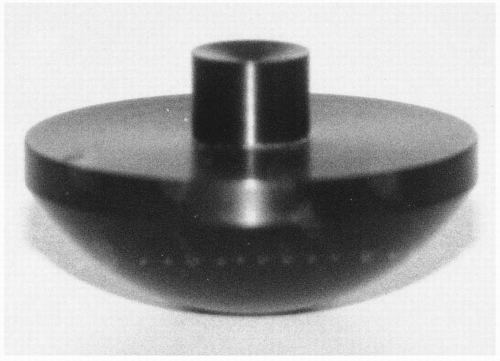
Place a small amount of water in the depression of the lens mount.
The lens should be clean and dry when placed in this depression, concave side upward. Caution should be taken to avoid submerging the entire lens or allowing any fluid on the concave surface as this will result in an inaccurate reading or a poor-quality image (Fig. 7.2).
Center and position the lens mount so that a small green beam of light can be observed reflected in the lens. The aperture selector should be in the large aperture position at the back of the instrument.
Viewed in the oculars, the real and aerial images will be observed as a spoke or star pattern (Fig. 7.3). The real image will appear at the lower end of the scale at approximately zero and will be centered; however, the aerial image will be located approximately 6 to 9 mm on the scale and may not be centered. This aerial image should be centered, and the lens mount should not be moved again before setting the instrument at zero and a reading is taken. Note that between the two images, the light filament (Fig. 7.4) will be observed.
On obtaining a clear, sharp spoke pattern of the real image at the lower end of the scale, place the needle on zero. This can be accomplished by using the knob located at the left side of most radiuscopes and the back of most radiusgauges (Fig. 7.5). The manual provided with the instrument should provide this information.
The objective should be adjusted with the coarse adjustment knob to obtain a clear, sharp image of the aerial image. As the scale increases in value, the light filament will be observed before the aerial image is viewed. The BCR will be the reading taken from the zero point to the clear, sharp image of the aerial image.
The BCR is read off the millimeter scale to the nearest hundredth. The millimeter scale is located in the ocular of the radiuscope and on a clock dial at the back of the radiusgauge. For example, a typical BCR would be recorded as 8.20 mm.
If the needle of the instrument will not position at zero when the real image is in focus, the nearest whole number should be used. This whole number will be added or subtracted from the final reading. For example, if the real image is in focus at +1.0 and the final reading is 7.0 mm, the BCR is 8.0 mm.
Verification of the BCR of gas-permeable (GP) contact lenses is also possible with several automated keratometers. These devices have been found to accurately measure the base curve radius within tolerance.1
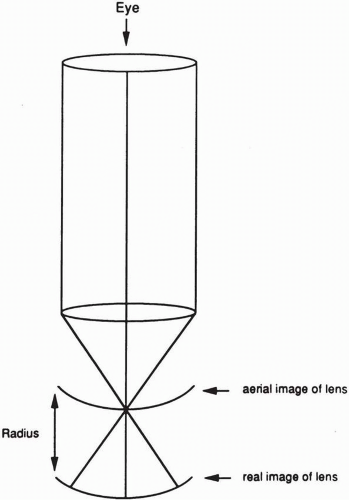 ▪ FIGURE 7.1 Diagram demonstrating that base curve radius is the difference between real image and aerial image. |
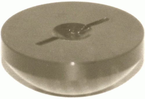 ▪ FIGURE 7.2 Lens mount for determining base curve radius. |
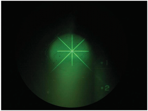 ▪ FIGURE 7.3 Spoke pattern observed in the radiuscope. |
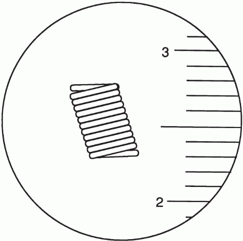 ▪ FIGURE 7.4 Diagram of light filament observed in the radiuscope. |
Front (Convex) Curve Radius
In addition to measuring the BCR, it may be necessary to measure the convex radius—for example, with front toric and bitoric lenses. A different lens mount is used to determine the convex radius (Fig. 7.6). The procedure is similar to determining the BCR with the exception that the real image is now the upper image and the aerial image is now the lower image. The needle should be set at the nearest whole number when the real image is in focus. When the aerial image is in focus, the number is read from the scale and subtracted from the whole number. For example, if the real image is in focus at 8.00 mm and the aerial image is in focus at 1.00 mm, the resulting front curve radius would be 7.00 mm.
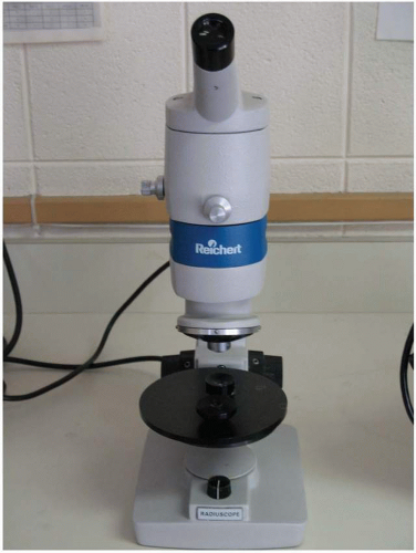 ▪ FIGURE 7.5 Radiuscope. |
 ▪ FIGURE 7.6 Lens mount used to measure the convex surface. |
Toric or Warped Lenses
The steps for determining a toric or warped lens are similar to those for determining the BCR; however, the spokes of the image will not all be in focus at the same time. First, one set of spokes will come in sharp focus; this will represent the steeper curve. The spokes 90 degrees away from the first set of spokes will next come in focus, and this is the flatter curve. The symptoms of a patient wearing a warped lens will vary from no subjective symptoms but slightly reduced visual acuity to subjective symptoms of blur and decreased visual acuity, accompanied by a spherocylindrical over-refraction. These symptoms alone will not indicate a warped lens. Verification of the BCR is necessary as lens flexure may also produce these symptoms. A lens that is flexing may appear warped immediately on removal; however, typically it will return to the original spherical state soon after removal. Patients exhibiting lenses that are warped will require re-education in the proper care and handling of GP lenses because poor care habits, such as cleaning the lenses between the index finger and thumb instead of the palm of the hand, will greatly increase the likelihood of lens warpage.
Peripheral Curve Radius
The peripheral curve radius can be determined by the same method as BCR; however, if the peripheral curve is not ≥1 mm in width, it is unlikely that it can be obtained. Typically, this is not a parameter that the practitioner can verify.
▪ VERIFICATION OF LENS POWER
Spherical Lenses
Back vertex power is typically the method by which power is determined for contact lenses. For low-power lenses, there is very little difference in back and front vertex power; however, there can be as much as 1 D difference in back and front vertex lenses in high prescriptions.4 If there is doubt about which surface power to verify, it would be best to check with the laboratory that supplies the lenses.
Back vertex power of contact lenses is determined similarly to spectacles. The lensometer should be adjusted for the individual user before the lens power is verified as specified in the instrument manual. The lens is placed concave side against the lens stop of the lensometer, and the power drum is adjusted until a clear image is achieved. The lens should be clean and dry.
It will be necessary to tilt the lensometer upward into a vertical position to allow the lens to rest on the lens stop or for the lens to be gently held on the lens stop with the thumb and forefinger. Caution should be taken not to flex the lens. Most lensometers have a contact lens accessory device that can be placed on the lens stop to aid in more accurate measurements.
It will be necessary to tilt the lensometer upward into a vertical position to allow the lens to rest on the lens stop or for the lens to be gently held on the lens stop with the thumb and forefinger. Caution should be taken not to flex the lens. Most lensometers have a contact lens accessory device that can be placed on the lens stop to aid in more accurate measurements.
Prism
To measure prism on a contact lens, the lens must be centered with the concave side against the lens stop. The reticule inside the ocular consists of concentric black rings designating 1 to 5 prism diopters. For example, when the center of the target is on the first concentric ring of the reticule, it corresponds to one prism diopter (Fig. 7.7). Prism is primarily used in front toric lenses to reduce rotation.
Toric Lenses
Front toric lenses should be placed on the lensometer with the prism in the base-down direction. The resulting power will be recorded in a spherocylindrical notation. For example, if the lens is positioned so the prism indicates one prism diopter base down and the power drum indicates powers of −1.00 D and −3.00 D at 90, the power would be recorded as − 1.00 − 2.00 × 90.
In toric lenses with no prism, such as bitorics and back torics, the power is not recorded in the spherocylindrical form, but as the values found in each meridian. An example of this is as follows:
BCR: 7.50/8.04 mm
Powers: P1/−3.00 D
▪ VERIFICATION OF CENTER/EDGE THICKNESS
A dial gauge is the most frequently used method of determining lens thickness. The lens is positioned on the gauge, and a plunger is lowered onto the lens with the thumb (Fig. 7.8). The center thickness (CT) or edge thickness can be measured by changing the portion of the lens beneath the plunger. The thickness is read directly off the gauge; for example, if the needle is on 23, then the thickness is recorded as 0.23 mm. Lens thickness can also be determined with the Marco radiusgauge because a thickness gauge is incorporated into the instrument itself. It is important to verify this parameter in cases pertaining to flexure, oxygen transmission, comfort, and lens position.5
Stay updated, free articles. Join our Telegram channel

Full access? Get Clinical Tree


