The Cross Cylinder
Stuart E. Wunsh
The invention of the cross cylinder can be traced back to the early 19th century. In 1837, the astronomer Sir George Biddle Airy1 made a cylindric lens and used it to correct astigmatism. Astigmatism was not readily recognized in those days, and when instances were found they were reported in the literature. The trial lens sets of that era contained no cylindric lenses; when such lenses were prescribed, they could be obtained only on special order from a few laboratories.
In response to the growing recognition of astigmatism and the need to correct it, a device called the Stokes lens was introduced in 1849.1 This lens consisted of two cylinders, one planoconvex and one planoconcave, with flat surfaces approximated and arranged so that they could be rotated in opposite directions. When the axes of the two cylinders were parallel, the resultant power was zero; when the axes were perpendicular, a spherocylinder with maximal power for that pair of lenses was formed. In practical use, you should first determine the axis of the astigmatism by rotating the lens before the eye, with some arbitrary setting; then, while maintaining the proper axis before the eye, try various strengths of cylinders. Each of the two cylinders in the Stokes lens had a power of approximately 4 diopters (D). The instrument could, therefore, create spherocylinders between 0 and No+4.00 D sph No–8.00 D cyl. No–8.00 D cyl. |
In 1885, W. S. Dennett improved the lens mounting and tried to popularize the instrument.2 Edward Jackson realized the instrument’s potential for determining cylinder power and reported his results in 1887.3 The Stokes lens remained little more than a curiosity, however, until 1907, when the cross cylinder’s usefulness in determining the axis of astigmatism was realized. The modified Stokes lens with axes fixed perpendicular to one another came to be known as the “Jackson crossed cylinder,” but the term cross cylinder is now perhaps more popular.
Although Jackson did describe his findings, it remained for W. H. Crisp, a more prolific writer, to bring this device to worldwide attention.4 The form of the instrument is a fixed arrangement of a plus and a minus cylinder, axes perpendicular, with a handle placed between the two axes. The following powers may be obtained:
+ 0.12 D cyl × 90° no–0.12 D cyl × 180° no–0.12 D cyl × 180°+ 0.25 D cyl × 90°  no–0.25 D cyl × 180° no–0.25 D cyl × 180°+ 0.50 D cyl × 90°  no–0.50 D cyl × 180° no–0.50 D cyl × 180°+ 1.00 D cyl × 90°  no–1.00 D cyl × 180° no–1.00 D cyl × 180° |
Written in this form, it is clear that we are dealing with cylinders (cyl). The spherical notation (sph) may be used (i.e., no+0.12 D sph no–0.25 D cyl × 180°), but this suggests the presence of spherical power. Some cross cylinder lenses are ground as a sphere on one surface and a cylinder on the other for economic reasons. The optics can be thought of much more easily if the cylindric components are emphasized.
The question of the possible spherical component of the cross cylinder and its effect on the final correction has not been settled. This question has nothing to do with the notation of the lens or whether it is ground as two cylinders or as one sphere and one cylinder, but it is concerned with the total effect of the lens on the object viewed. When it is introduced before the tentative correction, does the cross cylinder change the spherical power, or does it merely expand the conoid of Sturm? Jackson3 and others2,5 believed that the cross cylinder acts as two separate cylinders; it enlarges the conoid of Sturm but does not change the spherical power. Opposing arguments contend that spherical power has been added to the correction by the cross cylinder and that this must be compensated for when the cross cylinder is removed.
I believe that the cross cylinder, even though it can be expressed in spherical form, is not a np–0.50 sphere with a plus cylinder axis 90° away, but rather an infinite series of powers at an infinite number of meridians, resulting in an enlargement of the conoid of Sturm.
In point of fact, the question of spherical power in the cross cylinder is moot. Refraction is a dynamic process.6,7 As the final correction for a given patient is approached, all of the parameters of the refraction may be rechecked several times. In this way, any alterations in spheric power that may be induced by the cross cylinder are obviated.
DETERMINATION OF CYLINDER AXIS
The following definitions of terms will aid in understanding the mechanical technique of determining cylinder axis with the cross cylinder. The term twirl means a “flipping” of the lens before the eye in such a way that the side of the cross cylinder facing the patient at the beginning of the maneuver comes to face the examiner at the conclusion of the maneuver. The term rotate refers to a clockwise or counterclockwise motion of the cross cylinder in front of the patient, in the plane of the spectacle lens, about an axis parallel to the line of sight. The term correcting cylinder refers to the cylindric lens in the trial frame. This may represent either the tentative or the final correction, depending on the stage of the refraction. The term resultant denotes the total dioptric power obtained when different lenses are superimposed.
The first step in determining cylinder axis is to choose a tentative sphere and cylinder. The sphere is then adjusted so that the patient can read 20/40 (6/12 [metric equivalent])* or better. At this point, there should be a state of meridional balance, which is achieved when the conoid of Sturm is straddling the retina. (The duochrome test is a method of checking for meridional balance.)
The cross cylinder is now placed in front of the correcting cylinder, with its handle parallel to the axis of the correcting cylinder. In this position, the axes of the cross cylinder straddle the axis of the correcting cylinder at 45° each. It is explained to the patient that both images to be presented may be slightly blurred, but one may be clearer than the other. The patient is to state which position of the cross cylinder presents the clearer image (position 1 or position 2) or whether they appear alike. The clearer image is the one that is sharper, darker, or more legible. The end point of the test is reached when no difference can be discerned between the two positions of the cross cylinder.
The cross cylinder is then twirled in front of the correcting cylinder. This maneuver reverses the positions of the plus and minus axes of the cross cylinder. If both positions appear equally clear (or equally blurred), then the axis of the correcting cylinder is at the proper meridian and the test for axis is complete. If one position is clearer, the correcting cylinder is rotated toward the axis on the cross cylinder having the same sign as that of the correcting cylinder. Assume that a minus cylinder is being used as our correcting cylinder, and the patient selects the clearer position of the cross cylinder. We locate the minus axis of the cross cylinder in that position and rotate the correcting cylinder toward that axis 5° or 10°. (If plus cylinders were used for correction, we would rotate the correcting cylinder toward the plus axis of the cross cylinder in the preferred position.) The reason for this maneuver is explained later in the chapter. The cross cylinder is then relocated so that its axes once more straddle the axis of the correcting cylinder in its new position, and the test is repeated. When twirling the cross cylinder produces equal clarity (or blurring), the end point of the procedure has been reached and the axis of astigmatism has been identified.
THEORY OF AXIS DETERMINATION
The cross cylinder is particularly sensitive in assisting the patient in the selection of the proper axis of her astigmatism. When the cross cylinder straddles the presumed cylinder axis in the trial frame in one position, it creates a new cylinder whose axis is approximately 40° away from the original axis and increases the power of the cylinder; however, in the other position, the axis will jump 40° in the opposite direction but reduce the power. The patient easily perceives this change, seeing the lower-powered cylinder as clearer, and the appropriate steps may be taken by the examiner. Many texts at this point refer to the complexity of understanding the mathematics that show why the foregoing occurs and pass onto another topic.
With regard to the cross cylinder and axis determination, comprehending the first paragraph is all you will need to be a successful refractionist. The following demonstrates the above mathematically.
The full power of the cylindric lens lies 90° from its axis. For example, no+1.00 D cyl × 180° has for its power at the 180° meridian 0 D and at the 90° meridian no+1.00 D. What may not be generally appreciated is that between these two meridians (180° and 90°) the lens has dioptric power. In the example just mentioned, this begins with 0 D at 180° and increases at each meridian to the maximum power, no–1.00 D at 90° (Fig. 38-1). Of course, this applies to any cylinder regardless of power, sign (plus or minus), or axis. A cylinder will have a power of 0 D at its axis and increasing plus or minus power at each meridian, reaching a maximum (i.e., the stated power of the cylinder) 90° from the axis.
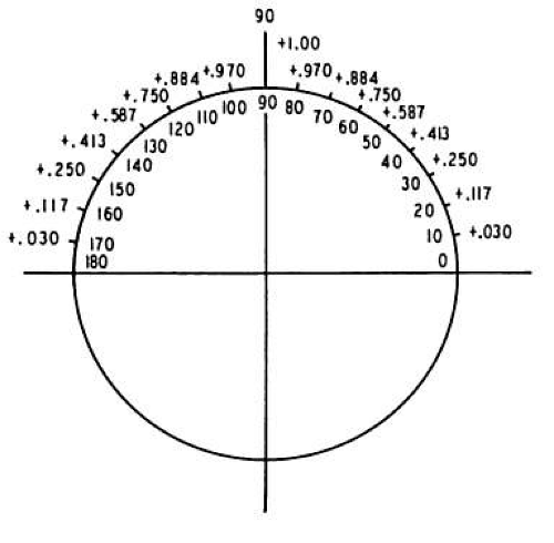 Fig. 38-1. no+1.00 D cyl × 180°. Power indicated at each 10° meridian. (From Wunsh SE: The cross cylinder. Int Ophthalmol Clin 11:131, 1971, with permission.) |
The power at each meridian of the lens is a function of the sine of the angle between the given meridian and the axis of the cylindric lens. To review, the sine of an angle in a right triangle is determined by the ratio between the length of the side opposite the angle and the length of the hypotenuse of the triangle. For a given angle θ, it may be written as follows (Fig. 38-2):
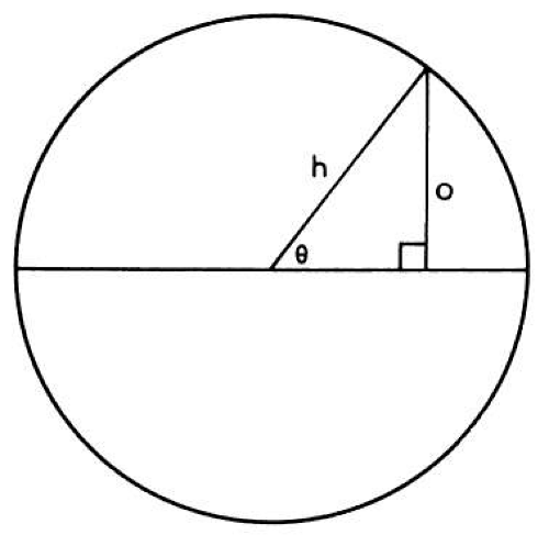 Fig. 38-2. Sin θequals side opposite given angle divided by the length of the hypotenuse. (From Wunsh SE: The cross cylinder. Int Ophthalmol Clin 11:131, 1971, with permission.) |
The sine of 0° is 0, the sine of 90° is 1, and the sine of 180° is once again 0. Between 0° and 90°, the values of sine increase from 0 to 1; they show a corresponding decrease between 90° and 180°. The sines of angles from 0° to 180° may be plotted on a graph, as shown in Figure 38-3 (the round points), and give rise to the sine curve. Many wavelike or cyclic phenomena may be described by a sine curve. In our current example, the changing powers of a cylindric lens seem to follow this curve.
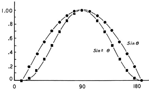 Fig. 38-3. Curves generated by functions sin θand sin2 θ. Curve sin2 θclosely approximates changing power of a cylindric lens at each meridian. (From Wunsh SE: The cross cylinder. Int Ophthalmol Clin 11:131, 1971, with permission.) |
Two additional factors slightly complicate this discussion. First, the relationship between the angle and the cylinder power is more accurately described by the square of the sine. That is, Dm (the dioptric power at any meridian of a cylindric lens) is equal to D (the maximum power of the cylinder) multiplied by the sine squared of the given angle (8). This is written Dm = D sin2 θ. (The curve of sin2 θis described by the square points in Figure 38-3.) Second, this formula is still only an approximation. The true values for cylinder power are obtained through a more complex formula; however, the values derived by the use of this approximate formula are accurate enough for our purposes.
If two cylinders of equal strength but opposite sign are placed one before the other with axes superimposed, they will neutralize each other. For example, if a no–1.00 D cyl × 180° is placed before a no+1.00 D cyl × 180°, the resultant power is zero. The no–1.00 D, which is the power in the vertical meridian of one lens, is neutralized by the no+1.00 D in the same position in the other lens. In addition, at each meridian between 0° and 180°, the powers present are equal but of opposite sign, thus neutralizing each other as well.
If, however, the axes were not perfectly aligned, we would have to add, algebraically, the powers present at each meridian and arrive at a resultant power. For example, beginning with a cylinder no+1.00 D × 180°, as pictured in Figure 38-1, we will superimpose a no–1.00-D cylinder but place its axis at 170° (10° “off axis”) (Fig. 38-4). Note that at 90° in Figure 38-1, we have no+1.00 D; at 90° in Figure 38-4, we have no–0.970 D. The resultant in this meridian is no+0.030 D; this calculation is repeated at each 10° meridian.
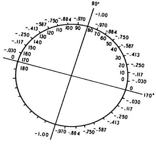 Fig. 38-4. no–1.00 D cyl × 170°. Power indicated at each 10° meridian. (From Wunsh SE: The cross cylinder. Int Ophthalmol Clin 11:131, 1971, with permission.) |
The resultant is pictured in Figure 38-5. We have created a spherocylinder, the formula of which may be written no+0.174 D sph nono–0.348 D cyl × 130°. Note the following: our –1.00-D cylinder no longer neutralizes our no+1.00-D cylinder. A new cylinder has been formed, in which the axis (using minus cylinder notation) is approximately 40° removed from the axes with which we began (i.e., 180° and 170°). A small error in the placement of the axis of the correcting cylinder produces a large displacement of the axis of the resultant cylinder. nono–0.348 D cyl × 130°. Note the following: our –1.00-D cylinder no longer neutralizes our no+1.00-D cylinder. A new cylinder has been formed, in which the axis (using minus cylinder notation) is approximately 40° removed from the axes with which we began (i.e., 180° and 170°). A small error in the placement of the axis of the correcting cylinder produces a large displacement of the axis of the resultant cylinder. |
 Fig. 38-5. no+0.174 D sph  –no0.348 D cyl × 130°. Resultant of superimposing Figures 38-1 and 38-4. (From Wunsh SE: The cross cylinder. Int Ophthalmol Clin 11:131, 1971, with permission.) –no0.348 D cyl × 130°. Resultant of superimposing Figures 38-1 and 38-4. (From Wunsh SE: The cross cylinder. Int Ophthalmol Clin 11:131, 1971, with permission.) |
Suppose the correcting cylinder were displaced by an even greater amount. Again, begin with a no+1.00 D cyl × 180° and superimpose a no–1.00-D cylinder, but this time displace the axis 30° (i.e., axis at 150°; Fig. 38-6). The resultant of this combination may be seen in Figure 38-7. The spherocylinder is no+0.50 D sph no–1.00 D cyl × 120°. With the correcting cylinder equal in power to the cylinder to be neutralized, an error in axis placement of 30° produces a new astigmatism equal in power to the original cylinder. no–1.00 D cyl × 120°. With the correcting cylinder equal in power to the cylinder to be neutralized, an error in axis placement of 30° produces a new astigmatism equal in power to the original cylinder. |
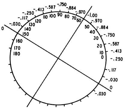 Fig. 38-6. no–no1.00 D cyl × 150°. Power is indicated at each 10° meridian. (From Wunsh SE: The cross cylinder. Int Ophthalmol Clin 11:131, 1971, with permission.)
Stay updated, free articles. Join our Telegram channel
Full access? Get Clinical Tree
 Get Clinical Tree app for offline access

|