Prescribing Multifocal Lenses
James E. Sheedy
Bret J. Andre
Multifocal spectacle lenses are primarily used in the treatment of presbyopia. Secondary usages include treatment of esophoria and pre-presbyopic accommodative dysfunctions such as reduced accommodative amplitude or accommodative infacility.
Until the early 1980s almost all multifocals were segmented bifocal and trifocal lenses. Since that time there has been steady growth in usage of progressive addition lenses (PALs), and approximately 50% of multifocals currently dispensed in the United States are of progressive design.
There are significant optical differences between and within the segmented and progressive multifocal lenses that affect the vision that is provided to the patient. The primary objectives of this chapter are to present and discuss those optical differences as they apply to meeting the viewing needs of individual patients and to the fitting, adjustment, and adaptation to the lenses.
HISTORY
Benjamin Franklin is commonly credited with inventing bifocals in 1784. He simply cut his round distance and near lenses in half and bound them together in a frame to create a bifocal. Although it appears Franklin invented bifocals independently, S. Pierce (1760) and A Smith (1783) also apparently independently invented them.1 As might be expected, the two-piece lenses had poor structural integrity in the frame and debris accumulated at their junction. Schnaitmann (1837) produced and patented the first one-piece bifocal by grinding the top of a reading lens to produce the distance power in the upper portion of the lens. An unfortunate consequence, however, was poor optics due to a large amount of base-down prism in the top portion of the lens.
B.M. Hanna (1884) developed and patented the cemented bifocal, which consisted of a thin round reading lens cemented to the back surface of a distance lens with Canadian balsam. This lens had better optics than previous designs but still had the difficulties associated with two-piece lenses. B.M. Hanna (1886) also introduced the Perfection Grooved Bifocal, which was an improved two-piece lens similar to the Franklin bifocal. It had a half-moon curved reading portion and also a bevel/groove interface between the two lenses that improved stability.
The modern multifocal era began with introduction of Kryptok, the first fused bifocal. It was invented in 1908 by John L. Borsch, a Philadelphia ophthalmologist, and was a 22-mm round bifocal segment. The bifocal segment was made of flint glass (index 1.654, Abbe value 35) fused with heat (>1,000°F) into a distance lens fabricated of crown glass (index 1.523). The Kryptok became a popular bifocal because it did not suffer from the instability of the cemented type, the segment was less conspicuous, and it eventually became the least expensive to produce. A one-piece bifocal (Ultex) was constructed in 1910 by Connor, an Indianapolis optician. This design involved grinding a round bifocal segment onto the distance portion of a single piece of glass. The result was a lens having a construction similar to that of the cemented bifocal but without any of the previously mentioned disadvantages. In 1915, the flat-top bifocal of fused construction was patented by Courmettes, a French citizen and resident of New York City. This was one of the segment styles introduced and manufactured by Univis Lens Company of Dayton, Ohio, in 1926. These newer fused bifocals used a barium glass for the segment (index 1.632, Abbe value 56) primarily because it has a better Abbe value and hence lower chromatic aberration compared to flint glass. The one-piece Franklin-style bifocal was introduced by American Optical Company in the early 1950s under the trade name Executive. This lens is based on the same principle as the first bifocal invented by Benjamin Franklin, with the optical centers of the distance and near portions placed adjacent to each other. Trifocals were introduced in 1826 by Hawkins of London. The first trifocal patents were taken out by Aves in England in 1907 and by Boness in America in 1911.
Throughout the history of multifocal lens development there has been an effort to devise a lens with an invisible segment. As early as 1916, Stead Optical Company made and patented a one-piece bifocal in which the boundary between the distance and near portions was rounded or blended. The most common method to accomplish this is with a progressive addition lens in which the power changes gradually from distance to near. The first PAL design was patented by Owen Aves in 1907. However, few advances occurred until 1951 when the Varilux 1 was developed by Maitenaz in France.2 It was not until 1962 that Omnifocal became the first PAL available in the United States. The Varilux 1 lens was introduced in the United States in 1965, followed by the Varilux 2 in 1973. Since that time numerous PALs have been introduced to market.
SELECTING THE MULTIFOCAL FOR THE PATIENT
The many optical differences between the various multifocal designs create different visual environments for the patient. The differences between categories (bifocals vs. PALs) and within categories are large and can significantly affect patient performance, comfort, and acceptance. The patient’s occupational and recreational pursuits should be identified and analyzed to determine unique viewing distances or viewing angles. Previous experience with multifocal lenses is instrumental in determining the new correction. Satisfaction with the current multifocal design nearly always predicts repeat success—however, it does not necessarily mean that the patient’s vision cannot be improved with a different design. Many patients who currently wear bifocals appreciate the better vision and cosmetics of a PAL, or patients successfully wearing one PAL design can often appreciate a different PAL design that suits their visual needs better.
DETERMINING THE ADD
Traditional multifocal lenses are constructed with the multifocal optics on the front surface of the lens; the curvature of the back surface is fabricated to provide the distance prescription of the patient. The power of the multifocal lens is “in addition” to the distance refractive power required for the patient and is specified in the optical prescription as the amount of plus power in the “add.”
Most clinicians perform routine near vision testing and determine the power of the add at a near viewing distance of 40 cm or 16 inches. Each clinician establishes for himself or herself a successful method for determining the appropriate add for the patient.
The most common methods of determining the 40-cm add are the following:
Remaining amplitude of accommodation. The basic tenet of this approach is that a patient can comfortably use only Y percentage (usually assumed to be 50%) of the remaining amplitude of accommodation (AA). The formula for this is as follows:

Example: The patient has remaining accommodation of +1.50, a viewing distance of 40 cm, and assume the patient can use 50% of the remaining accommodation. The calculation is 1/.4 – (0.5 × 1.5) = +1.75 D add.
Midpoint of the plus range. This procedure involves placing a target at the specified test distance (usually 40 cm) and determining the most and least amounts of plus that enable clear vision. The add amount is prescribed as the midpoint.
Binocular cross cylinder test. The patient views horizontal/vertical grid lines with cross cylinders placed with the minus axis at 90 degrees. The add is the minimum amount of plus required to equalize appearance of the vertical and horizontal lines.
Trial lenses in free space. Measure the range of clear vision with trial lenses in free space. This method has the advantage that it shows patients what they will see with the prescription.
Any of these methods can be used to determine the add power for 40-cm or other viewing distance. The viewing distance is incorporated into the equation for the first method, and the other methods can be used with the target placed at the particular distance required by the patient. The fourth method, i.e., placing an object at the viewing distance and determining the add power that provides the best range of clear vision, can be particularly successful for unique viewing distances.
BIFOCALS
As the name implies, bifocals provide two power zones as shown in Figure 44-1. The primary lens contains the distance power, and the add segment contains the near power. All bifocals provide a large distance viewing zone with homogenous power, and most also provide a large near viewing zone with homogenous power. However, the two viewing zones have a sharp demarcation. Cosmetically the line of demarcation is quite noticeable and can be particularly disturbing to patients who are sensitive to showing their age. Visually the line of demarcation represents a largely unusable portion of the lens. If the eye rotates so that the line of sight is near the line, then the pupil receives light from both viewing zones. This results in diplopia because of the prismatic effects of the segment—and each image results from a different refractive power. The optical center of the add is not at the line (except in a Franklin-type segment, Fig. 44-2D); hence there is a base-down prismatic effect due to the add at the top of the segment. This prismatic effect is called image jump. The magnitude of the image jump (in prism diopters) is calculated by multiplying the power of the add (in diopters) by the distance from the top of the segment to the optical center of the add (in cm). The locations of the optical centers of the adds are indicated by the dots in Figures 44-2A–F and discussed further in later paragraphs. The magnitude of the image jump usually ranges from 0.5 to 4 prism diopters. Because of the double images and conflicting focus near the top of the segment, bifocal wearers habitually avoid fixating near the line and use saccadic eye movements to alternate between the distance and near viewing zones. Bifocal wearers experience a large zone of unusable visual space immediately below the primary gaze position; this is the primary visual compromise of bifocal lenses.
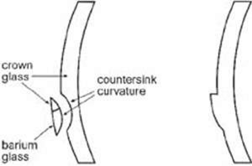 Figure 44-1. On the left is a fused flat-top bifocal. Fused bifocals are made only with glass material. On the right is a one-piece flat-top bifocal. All nonglass bifocals are one-piece. |
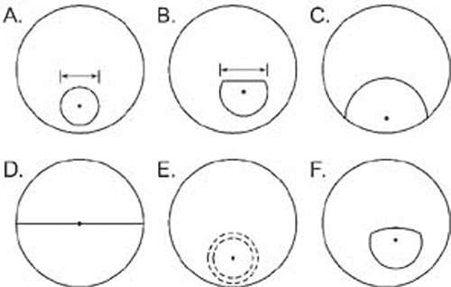 Figure 44-2. Commonly used bifocal types. A. Round segment, available in diameters of 15, 22, 25, 28, and 35 mm. B. Flat-top, available in diameters of 22, 25, 28, 35, and 45 mm. C. Ultex type, available in diameters of 38 and 40 mm. D. Executive bifocal. E. Round blended, diameters of 22, 25, and 28 mm. F. Curve-top, available in diameters of 25 and 28 mm. For each bifocal type the dot designates the location of the optical center of the add. For all types (except D), the location of the optical center is at the center of the segment circle. |
The shapes of the bifocal segments in the market today are essentially the same as those reviewed previously from a historical perspective. All bifocals were initially developed in glass, but today glass has a very small market presence and most bifocals are made from plastic, polycarbonate, TriVex, or other resin materials.
By far the most commonly prescribed bifocal is the flat-top (FT) or D segment, directly derived from the Univis “D” segment developed in 1926. (There also were segment shapes designated “A–C,” which were not as successful.) In glass product, then as today, the segment is formed by fusing a segment of barium glass (index of 1.623) to a crown glass (index 1.523) carrier lens as shown in Figure 44-1. The countersink curvature is calculated to provide the intended add amount and to enable the front curvature of the segment to match the curvature of the carrier lens. This results in a smooth front surface, and the bifocal junction is indistinguishable by touch. Note in Figure 44-1 that the countersink is actually circular and the flat-top is created by making the top part of the segment out of crown glass, which seamlessly blends with the carrier lens. All nonglass bifocals are of one-piece construction, meaning that the entire lens is made from the same material and that the power difference between the distance and near portions is created with changes in curvature. The segment is formed (molded) as part of the lens, and the power addition is created with a different curvature (Fig. 44-1). Because the surface has a discontinuity, it is readily identified by touch—the top of the bifocal segment forms a small ledge.
Available bifocal types are shown in Figure 44-2. The round segment (Fig. 44-2A) has evolved from the Kryptok bifocal and classically has a diameter of 22 mm although other diameters are available. A chief advantage of round segments is that they are the least noticeable cosmetically, especially if a light tint (such as pink) is used. Disadvantages of the round segment are that image jump is fairly large because the distance from the top of the segment to the optical center of the segment is fairly large—half of the segment diameter. Also, because the top of the segment is curved, the top portion of the segment provides little width of near vision and is not very useful. This effectively enlarges the zone of unusable vision at the top of the segment. The 15-mm round segment is useful for patients engaged in activities such as golf or outdoor labor where a segment is considered bothersome yet the patient still requires some near vision. One successful solution for golfers is to use a monocular 15-mm round segment located superiorly or temporally on the same eye as the handedness of the golfer. Glasses with 15-mm round segments are usually for special usage, and the patient will require a separate pair for other daily activities.
Flat-top (FT) bifocal segments (Fig. 44-2B), sometimes still referred to as “D” type segments, lessen the problems of the round segment at the top of the segment. By eliminating the top of the circle, useful near field width is attained immediately below the top of the segment line. Also, because the optical center of the segment for FT bifocals is 5 mm below the top line, the magnitude of the image jump is less than for round segments. FT bifocals have become the standard bifocal because of visual advantages, even though they are more noticeable cosmetically than round segments. FT28 is the most common width; however, other widths can be used dependent on the visual needs of the patient.
The Ultex type bifocal (Fig. 44-2C) is characterized by very large amounts of image jump (the optical center is 19–20 mm below the segment top) and by limited distance zone in the lower portions of the lens. Because of these characteristics, the lens is not well-suited for general use. However, it is a very good lens for hyperopic patients who perform considerable near work such as at a desk. This is because the hyperopic patient obtains base-up prism with depressed gaze—hence requiring excessive depressed gaze to view typical near materials. Base-down prism from the Ultex bifocal counteracts the prism from the plus distance lens and reduces the amount of required gaze depression for near materials. The Ultex bifocal should be considered for this specialty use, but the large amount of image jump at the segment top and the minimal distance zone in the lower lens are detriments to using the lens for general use.
The Executive bifocal (Fig. 44-2D), sometimes still referred to as a Franklin bifocal, has the advantages of an extremely wide near viewing zone and no image jump at the top of the segment because the optical center of the add is on the segment line. Despite these advantages, the lens is limited in scope because of the lack of any distance zone in the lower portions of the lens. This is very bothersome for ambulation and general daily wear. The lens is best suited to meet extensive near viewing needs such as at a desk. However, many practitioners prefer to use a FT35 or FT45 instead for these purposes.
The blended bifocal (Fig. 44-2E) is a variant of the round bifocal. The boundary between the distance and near zones is blended to produce an apparently seamless lens. Cosmetic appearance is the sole reason to use this lens because the blend area (2–3 mm wide) increases the area of unusable vision and decreases the diameter of the usable near vision zone. The curve-top bifocal (Fig. 44-2F) is intermediary to the round and FT bifocals and also possesses intermediary properties. Although it can be a successful general-usage lens, it has not enjoyed broad usage, probably because of the larger visual advantages of FT bifocals.
Patient Adaptation
First-time bifocal wearers will go through an adaptation period. Some of the most common problems involve the altered location of objects through the bifocal segment, creating problems with stairs, curbs, and similar situations. First-time wearers should be counseled about these initial problems.
Fitting Bifocal Lenses
For good visual performance, it is important that the bifocal lenses be properly placed within the frame and the frame properly fitted to the face. Before making measurements of lens location, the frame should be selected and fitted to the patient’s face, incorporating the appropriate pantoscopic tilt. Eyeglass frames with nose pad arms are preferred because they allow postfitting adjustment of the bifocal height.
Segment Height
The segment height is specified as the vertical distance from the top edge of the segment to the level of the lowest portion of the lens. The person making the measurement should be located straight in front of the patient and at the same eye level. For most patients the best location of the top of the segment is about 1 mm below the lower limbal margin. Round segments should be fitted about 1 mm higher than FT segments. Consideration should be given to the location of the previous bifocals (if the patient has previously worn them) and the patient visual needs and preferences. Observe the segment height location in the current bifocals; if the location seems reasonable and the patient is satisfied, then duplicate the location in the new spectacles. Sometimes the current bifocal height is considerably lower or higher (less commonly) than ideal, yet the patient expresses no complaint. Observe patient behavior with the current bifocals to determine if awkward posture is required to use the segment and/or probe with questioning. Change the height only with caution, but do so (probably only partially) if it will result in better vision and patient satisfaction. The patient’s particular viewing requirements should also be considered in determining the height of the bifocal. For patients with minimal near viewing requirements the height should be lowered whereas patients with extensive near viewing requirements should be fitted higher, perhaps even to the lower pupillary border. In nearly all cases, however, it is safer to err on the low side. Patient dissatisfaction occurs more readily with a segment that is placed too high.
Segment Inset—the Near Interpupillary Distance
The major reference point (MRP) of the lens is the location that contains the prescribed refractive and prism correction; the MRP is the same as the optical center if there is no prescribed prism. The MRPs of the distance portions of the lenses should be separated in the frame by the same amount as the patient’s interpupillary distance (PD). However, the bifocal segments should be separated by the same amount as the patient’s near PD. The monocular difference between the distance and near PDs is the segment inset, or the horizontal amount by which the center of each segment is nasally displaced with respect to the MRP.
Major influences on the segment inset include the distance PD (Table 44-1) and the near viewing distance, which is largely driven by the amount of the add (Table 44-2). However, other influences include the fitting vertex distance (back lens surface to corneal apex) and the power of the distance lens due to the base-in and base-out effects of converging through minus and plus lenses, respectively. To determine the segment inset, it is best to measure the near PD with the patient viewing the examiner’s eye at the intended near viewing distance and with the intended total lens power and vertex distance.
Table 44-1. Monocular Segment Inset as Function of Distance PD. Assumptions: No Distance Power, Vertex Distance 14 mm | ||||||||||||||||||||||||||
|---|---|---|---|---|---|---|---|---|---|---|---|---|---|---|---|---|---|---|---|---|---|---|---|---|---|---|
|
Table 44-2. Monocular Segment Inset as Function of Viewing Distance. Assumptions: No Distance Power, Vertex Distance 14 mm
Stay updated, free articles. Join our Telegram channel
Full access? Get Clinical Tree
 Get Clinical Tree app for offline access

|
|---|