Optics & Refraction: Introduction
The correct interpretation of visual information depends on the eye’s ability to focus incoming rays of light on the retina. An understanding of this process and how it is influenced by normal variations or ocular disease is essential to the successful use of any optical aid, for example, glasses, contact lenses, intraocular lenses, or low-vision aids. To achieve this understanding, it is necessary to master the concepts of geometric optics, which define the effect on light rays as they pass through different surfaces and media.
Geometric Optics
Speed, frequency, and wavelength of light are related by the following expression:
In different optical media, speed and wavelength of light change, but frequency is constant. Color depends on frequency, so that the color of a ray of light is not altered as it passes through optical media except by selective nontransmittance or fluorescence. The optical characteristics of a substance can only be defined with respect to clearly specified frequencies of light. A substance to be used for lenses to refract visible light is usually tested with the yellow sodium light (D line) and the blue (F line) and the red (C line) of a rarefied hydrogen discharge tube.
In a vacuum, the speed of all frequencies of light is the same, that is, 299,792.46 kilometers per second (186,282.40 statute miles per second). Since the frequency of the yellow D line is approximately 5.085 × 10¹⁴ Hz, the wavelength of this line in a vacuum is 0.5896 μm. Similarly, the wavelengths in a vacuum of the blue F and red C lines are 0.4861 and 0.6563 μm, respectively.
If the speed of a light ray is altered by a change in the optical medium, refraction of the ray will also occur (Figure 21–1). The effect of an optical substance on the speed of light is expressed as its index of refraction, n. The higher the index, the slower the speed and the greater the effect on refraction.

In a vacuum, n has the value 1.00000. The absolute index of refraction of a substance is the ratio of the speed of light in a vacuum to the speed of light in the substance. The relative index of refraction of a substance is calculated with reference to the speed of light in air. The absolute index of refraction of air varies with the temperature, pressure, and humidity of the air and the frequency of the light, but it is about 1.00032. In optics, n is assumed to be relative to air unless specified as absolute.
The index of refraction changes with the temperature of the medium—it is higher when the substance is colder. This lability of n to temperature is different for different substances. The change in n per degree Celsius for the following substances (all to be multiplied by 10–7) is as follows: glass, 1; fluorite, 10; plastic, 140; water, aqueous, and vitreous, 185. This makes plastic undesirable for precision optical devices. (Plastic also has 8 times the thermal expansion of glass.) Water lenses date back to antiquity but generally are not practical because of problems with thermal instability, evaporation, freezing, and susceptibility to contamination; but in the eye, these objections all but disappear, making the fluid lenses of the eye acceptable.
In a vacuum, the speed of all frequencies of light is the same; thus, the index of refraction is also the same for all colors (1.00000). In all substances, n is different for each color or frequency, being larger at the blue end and smaller at the red end of the spectrum. This difference can be quantified as the dispersion value, V:
where nD, nF, and nC are the indices of refraction for the yellow sodium line and the blue and the red hydrogen lines.
The higher the value of V, the lesser the dispersion of colors. Table 21–1 gives the indices of refraction and some dispersion values for substances of ophthalmologic interest.
| Substance (20 °C unless noted) | Indices of Refraction (nD) | Dispersion Values (V) |
|---|---|---|
| Water | 1.33299 | |
| Water 37 °C | 1.33093 | 55.6 |
| Sea water | 1.344 | |
| Sea water, 11,000 m depth | 1.361 | |
| Polymethylmethacrylate | 1.49166 | 57.37 |
| Polymethylmethacrylate 37 °C | 1.48928 | |
| Acrylonitrile styrene copolymer | 1.56735 | 34.87 |
| Polystyrene | 1.59027 | 30.92 |
| Fluorite | 1.4338 | 95.2 |
| Spectacle crown glass | 1.523 | 58.8 |
| Flint glass | 1.617 | 36.6 |
| Aqueous and vitreous 37°C | 1.3337 | 55.6 |
| Hydroxyethylmethacrylate (HEMA) | 1.43 | |
| Cellulose acetate butyrate (CAB) | 1.47 | |
| Silicone | 1.439 |
Optical materials vary in their transmittance or transparency to different frequencies. Some “transparent” materials such as glass are almost opaque to ultraviolet light. Red glass would be almost opaque to the green frequency. Optical media must be selected according to the specific wavelength of light with which they are to be used.
The laws of reflection and refraction were formulated in 1621 by the Dutch astronomer and mathematician Willebrod Snell at the University of Leyden. These laws, together with Fermat’s principle, form the basis of applied geometric optics. They can all be stated as follows (Figure 21–2):

Incident, reflected, and refracted rays all reside in a plane known as the plane of incidence, which is normal (at a right angle) to the interface.
For reflection, relative to the normal, the angles of reflection and incidence are equal.
For refraction, the product of the index of refraction of the medium of the incident ray and the sine of the angle of incidence of the incident ray is equal to the product of the same terms of the refracted ray (designated by a prime): n sin I = n′ sin I′ (Snell’s law).
A ray of light passing from one point to another follows the path that takes the least time to negotiate (Fermat’s principle). Optical path length is the index of refraction times the actual path length.
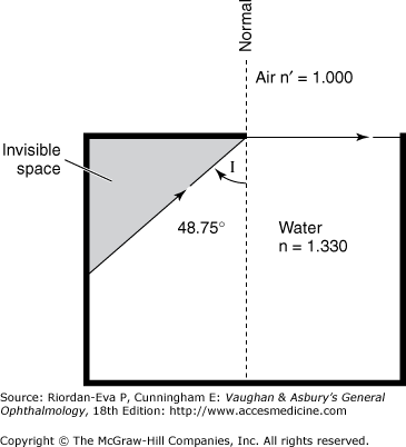
In the example of refraction in Figure 21–2, the arriving ray is in the less-dense medium (air) and is refracted toward the normal within the denser medium (glass). Conversely, if the arriving ray were in the denser medium, it would be refracted away from the normal. In this situation, as the angle of incidence is increased, the critical angle is reached when the light is totally reflected (total internal reflection) and the sine of the incident ray in the denser medium reaches the value n′/n. This is one method used to determine the index of refraction. For water, with an index of refraction of 1.330, the critical angle has the sine of 1/1.330, or 48.75° (Figure 21–3).
Total internal reflection obeys the laws of regular reflection, allowing perfect reflection without coatings and being used extensively in fiberoptics.
In Figure 21–3, the shaded area is not directly visible from the surface, explaining why visualization of the anterior chamber angle of the eye requires a gonioscopy lens (see Chapter 2). The index of refraction of the aqueous, not the index of refraction of the tears or cornea, is the determining factor in this context.
Calculations Used in Optics
There are two approaches to the application of the principles of geometric optics to single lenses or to compound lens systems. Trigonometric ray tracing is the more valid and exact approach, as it makes no assumptions other than those already determined by the laws of refraction. The algebraic method is a system based on a number of assumptions that greatly simplify calculation of the effects of various lens systems but also limit accuracy to an ever-increasing extent as the lens systems become more complex. The algebraic method cannot be relied on for accurate results, particularly in the assessment of the optical effects of contact lenses, intraocular lenses, and keratorefractive procedures.
Certain considerations are universal to optical calculations whatever method is used. For any optical system, the object and its image are said to lie in conjugate planes. If the object were to be placed in the plane of its own image, the optical system would produce its new image in the original object plane. Thus, the effects of any optical system will be the same for whichever direction light travels through the system. Each optical system has an infinite number of pairs of conjugate planes. Corresponding points on conjugate planes are known as conjugate points.
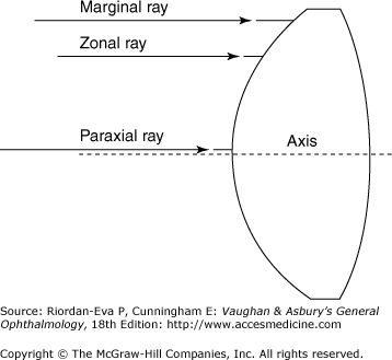
The trigonometric method of ray tracing consists of mathematically plotting the course of certain specified rays through the lens systems. The three rays most frequently traced are shown in Figure 21–4. They are named according to their positions relative to the first refracting surface. The marginal ray enters at the margin of the lens, the paraxial ray very near the optical axis (center of the lens), and the zonal ray in the portion of the lens where the average luminous flux of light passes through the lens. At each refracting surface, the change in direction of each of these rays is calculated according to the principles of Snell’s law. This requires knowledge of the radius of curvature of the surface, the index of refraction of the medium on each side of the refracting surface, and the distance to the next surface. Elementary trigonometry is the only mathematical skill necessary for such calculations, although a programmable calculator greatly assists with the number of such calculations that have to be carried out.
Trigonometric ray tracing provides an exact determination of the point of focus and information on the quality of the image formed by a lens system. The difference between the back focal lengths (distance along the optical axis from the last refracting surface to the point of focus) of the marginal and paraxial rays is a measure of the “spread of focus,” thus indicating the degree of spherical aberration (see later in the chapter). Similarly, if rays of different color (frequency), with their different indices of refraction in each medium, are traced through the system, the degree of chromatic aberration (see later in the chapter) will be determined. The optical pathway is the sum of the actual distance a ray passes through the substances multiplied by the index of refraction in the various substances through which it passes. How closely the optical pathways of the marginal and paraxial rays match determines the brightness and contrast of the final image.
Trigonometric ray tracing permits determination of the performance of each refracting surface relative to the contribution to the final image. For example, it is easily shown that a planoconvex intraocular lens gives a better image with the convex surface forward and the flat surface closer to the retina. The point of focus often requires—and is easily adjusted by—postoperative refraction. However, the distorted image caused by selecting an intraocular lens of improper shape cannot be repaired by refraction. Suitability in this respect must be achieved by proper preoperative lens design, and this can only be achieved by calculation using the trigonometric method of ray tracing.
Graphic ray tracing is a system comparable to trigonometric ray tracing that uses drawings to determine the optical properties of lens systems; it should not be confused with the method of “ray tracing” described in several books, in which tracings of an image are based on (a derivation of the algebraic method of optical calculations discussed below).
Carl Friedrich Gauss (1777–1855) is responsible for refining a method of optical calculations that dispensed with the sines and cosines of the trigonometric method. This assumed that the lenses are “infinitely thin,” placed close together, and of small diameter, such that any angle will be so small that the size of the angle measured in radians will have the same value as the sine of the angle and that the sine and the tangent of the angle can be assumed to be the same. The results are the thin lens equations used by opticians to calculate curves for lenses. “Fudge factors” derived from experience are then necessary to correct for the inaccuracies of these equations.
Use of the algebraic method depends on certain definitions. The position of the lens, reduced to a single line, is the principal plane, which intersects the optical axis at the nodal point (optical center). The primary focal point (F) is that point along the optical axis where an object must be placed to form an image at infinity. The secondary focal point (F′) is that point along the optical axis where parallel incident rays are brought to a focus. If the medium on either side of the lens is of the same refractive index, the distance between the nodal point and each of the focal points, the focal length, is the same.
Figure 21–5 shows some of the important thin lens equations.

The diopter (D) is a measure of lens power derived from the algebraic method of optical calculations. It is defined as the reciprocal of the focal length of a lens in air measured in meters. Diopters are additive, but only for low-power lenses. The result of combining lenses of high power varies greatly with their thickness and the separation distance. High-power lenses must be described by three values: (1) radii of curvature, (2) index of refraction, and (3) thickness.
In Gaussian optics, a thick lens is treated as if there are two nodal points and two principal planes (n and n′ and H and H′ in Figure 21–6). The nodal points lie on the principal planes only if the refractive medium is the same on either side of the lens. The true focal lengths are measured from the principal planes to the focal points, but the front and back focal lengths—essential to the prescription of corrective lenses—are measured from the respective surfaces of the lens to the focal points. The reciprocal of the back focal length corresponds to the back vertex power as measured with a lensometer.

For making high plus contact lenses or thick-spectacle lenses, according to the algebraic method the equation for lens power in diopters is:
where F = focal length, r1 = front surface radius, r2 = back surface radius, and d = thickness of lens, all measured in meters, and n = refractive index.
For contact lenses, a derivation of the thin-lens equations is presently used to relate dioptric power to radius of curvature:
n of “cornea” is for this purpose assumed to be 1.3375. rmm = radius in millimeters. These equations are only approximations.
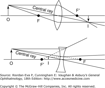
The ray tracing method commonly described in ophthalmic optics texts is a graphic representation of the algebraic system of optical calculations—in contrast to true graphic ray tracing, which is a graphic representation of the trigonometric system. Rays are traced through the optical system to connect conjugate points. The positions of the conjugate planes are derived mathematically from the thin lens equations. The size and orientation of the object are then determined by tracing the central ray, which passes straight through the tip of the image, the nodal point of the lens (without being refracted), and the tip of the object. The rays that traverse the focal points of the lens are derived by extrapolation (Figure 21–7).
For multiple lens systems, the conjugate planes and the path of the central ray are determined for each lens in succession, producing an image that becomes the object for the next lens until the size and orientation of the final image is located. In the case of a thick lens, refraction occurs at the principal planes of the lens, the position of rays being translated from one principal plane to another without any change in their vertical separation from the optical axis (Figure 21–6). The central ray passes from the tip of the object to the first nodal point and then emerges from the second nodal point parallel to its original direction to reach the tip of the image. When the media on either side of the lens have different refractive indices, the nodal points do not coincide with the principal planes.


