Fig. 5.1
Top view of the optical design (z-axis is vertical)
5.4 Suppression of Back Reflections
A challenging part at the design of a non-mydriatic fundus camera is the reduction of back reflections at optical surfaces. Those reflections can occur wherever the illuminating and observing light bundles interfere [3]. In our design this affects the field lens, the eyepiece, the cornea, and the lens of the eye. Back reflections within the eye occur at four surfaces, which are tagged with P1 to P4 in Fig. 5.1. They are causing the so-called Purkinje image nos. 1 to 4, respectively [4].
Without any further measures, it would not have been possible to acquire fundus images by the described way, because the back reflections would be many magnitudes brighter than the fundus image. Thus, several measures to reduce those back reflections were applied.
The first measure was to use an eyepiece and a field lens with an antireflection coating. For eyepieces this is a standard feature, which is included for nearly all products on the market. However, there are still remaining reflections, which are still too bright. Of course the eye does not have such a coating on its optical surfaces, too.
Therefore, another measure using polarized light [5] was applied. This means that one polarizer is put in front of the virtual light source in plane A2 (Fig. 5.1) and another one in front of the C-mount lens. The polarizing filters were relatively axially turned by 90° (“crossed”). As a consequence no light from the illumination could enter the camera as long as the polarization of the light was not changed. The field lens and the eyepiece did not change the state of polarization of the light, so that back reflections at their surfaces were nearly completely suppressed. Only small artifacts remained (Fig. 5.2), which could be suppressed by image post-processing, because they were reproducible. The Purkinje images were reduced in intensity, too, but the effectiveness decreased with the increasing number of the Purkinje reflection. This was due to birefringence within the cornea and lens, which changed the state of polarization. Finally the light was scattered on the retina, which depolarized the illuminating light so that an orthogonal polarization component was generated passing the second polarizer.
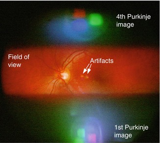
Fig. 5.2
Stripe-field method: reflections focused to unused upper/lower black stripes, gaining unlimited width of the field of view in the center
To suppress the Purkinje images, the light bundles of illumination and observation were separated at the aperture plane A1 (Fig. 5.1) [3, 6]. The position of this aperture plain was settled near the front side of the lens of the eye. Figure 5.3 shows the bisection of the aperture plane A1 to an upper observation section and a lower illumination spot. This prevented the disturbing rays, being reflected at the cornea or lens, from mixing up with the useful rays emerging from the retina.
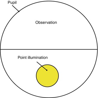
Fig. 5.3
Bisection of the aperture: separation of illumination from observation for suppression of the 1st and 2nd Purkinje reflections
The suppression of Purkinje images by aperture splitting only can work perfectly at the aperture plane itself. However, the origins of the Purkinje images are located at the cornea or lens and therefore have some axial distance to the aperture plane. Depending on this distance, the illuminating and observing ray bundles interfered more or less. Thus, the Purkinje images (especially the 1st and 4th) could be suppressed partially only.
To overcome this problem, a new method was found: The optics were designed in a way that the 1st and 4th Purkinje images were not blurred over the whole fundus image, but focused to peripheral areas of the image plane. The remaining space between the 1st and 4th Purkinje images was free of artifacts and was used for imaging. Therefore, a stripe-shaped field of view was used, because it fitted in between the reflections (Fig. 5.2). There is an important difference between the described stripe-field method and stripe aperture devices as described in the literature [7] or other devices based on slit lamps. In those devices the aperture plane and not the image plane is divided into stripes.
Thus, the stripe-field method combined with the other measures being described makes it possible to capture wide-field fundus images being free of reflections and artifacts.
5.5 Video Capability with a Large Field of View
Many conventional non-mydriatic fundus cameras use a ring illumination, which is different from our stripe-field method. The main disadvantage of conventional ring illumination is that the field of view decreases with a decreasing pupil diameter. For example, when the pupil shrinks down to 1.58 mm, the possible field of view is only 20° [8]. This is why many common fundus cameras with 45° field of view normally need at least about 4 mm pupil diameter to work properly. Some cameras offer a small pupil mode with a reduced field of view. This shows the correlation between pupil diameter and maximum field of view. This is a major problem of that method, because after activating the illumination, the pupil will quickly shrink below the critical diameter. Therefore, the ring illumination cannot be continuous, but must be “flashed” to quickly capture an image before the pupil shrinks. If another image has to be taken, one has to wait up to some minutes until the pupil has enlarged above the limit again. At permanent illumination, which is required for video acquisition, the pupil would shrink down to about 1.5–2 mm, resulting in a field of view of only about 20°.
Our stripe-field illumination method solved the described small pupil problem. The advance in the method was that the rotational symmetry of the ring illumination was left. The square field of view offered the two parameters height and width of the field of view. Those parameters were two degrees of freedom being available for optimization. This is one parameter more compared to the conventional ring illumination where only the diameter could be optimized. This was used to load all the “small pupil problems,” which reduced the maximum angle of view, to the vertical axis, leaving the horizontal axis free of those problems. This means that the height of our image was still limited by the pupil size to about 20° like it is at ring illumination, but the width of the fundus image became unlimited in principle. Practically the width of the field could be extended as far as the eyepiece can afford. Thus, the new method allowed a continuous illumination of the fundus while still having a wide-field and artifact-less view to the fundus. This offered the possibility to acquire wide-field videos. Furthermore, if only one still image were needed, then many video frames could be averaged by post-processing to drastically increase the clarity (see below).
5.6 Positioning of the Fundus Camera
Especially for non-mydriatic fundus cameras, it is necessary to correctly align the camera to the eye, because the very small pupil has to be targeted and does not left much space for misalignments. Therefore, an accurate positioning method was essential for a reliable operation. Fortunately, our stripe-field imaging method offered the complimentary feature for pupil tracking in three dimensions without the need for any further design features in hardware. This was achieved by taking advantage of the Purkinje images (especially image nos. 1 and 4) above and below the field of view, which are also captured by the CCD (Fig. 5.2). The position and shape of those reflections sensitively revealed a displacement of the device in all three spatial dimensions. Figure 5.4a shows the Purkinje images at a correct alignment and also at a displacement in each of the three spatial directions (Fig. 5.4b–d). The operator of the fundus camera was able to align the camera to the subject continuously by watching the reflections on the live preview of the control software.
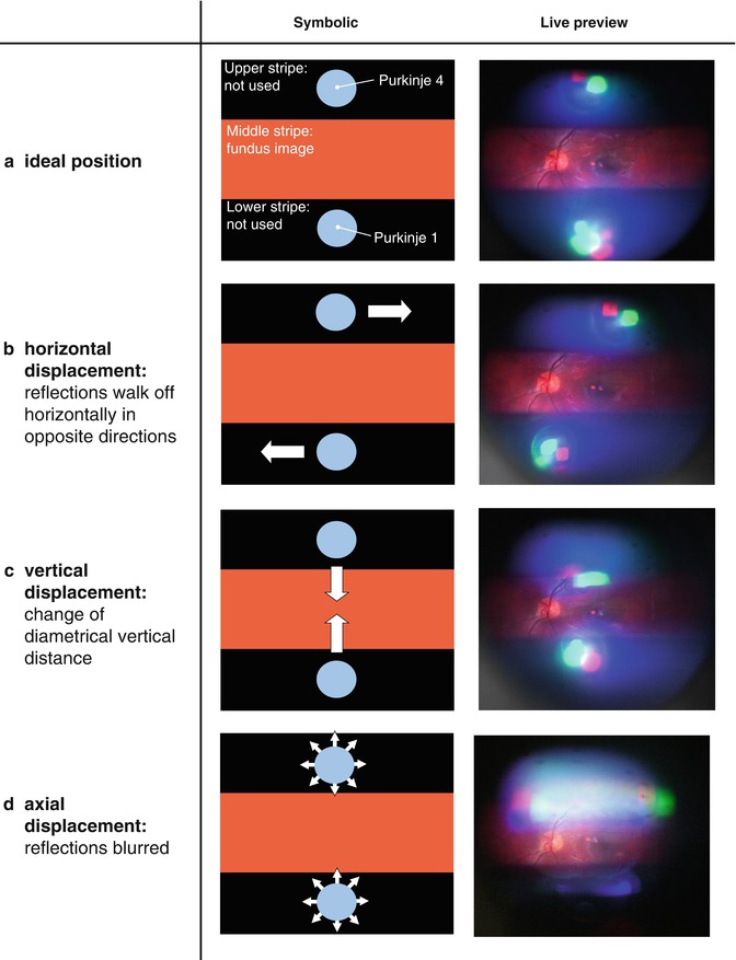
Fig. 5.4


Positioning method by Purkinje reflections: signs of displacement seen by the operator at the live preview. (a) Ideal positions; (b) horizontal displacement, reflections walk off horizontally in opposite directions; (c) vertical displacement, change of diametrical vertical distance; and (d) axial displacement, reflections blurred
Stay updated, free articles. Join our Telegram channel
Full access? Get Clinical Tree
