Lasik Instrumentation: Microkeratomes, Excimer Lasers, and Wavefront Analyzers
Raymond S. Loh
David R. Hardten
At the onset of the 21st century, the basic requirements of any refractive surgery remain unchanged with the primary goals of safety, reproducibility, accuracy and, stability being foremost in the surgeons’ mind. With advances in microkeratome design, laser technology, and eye-tracking, the accuracy and reproducibility of laser refractive surgery has improved. The development of commercially available wavefront-sensing devices and the improvements in laser technology have paved the way for potential treatments of lower and higher order optical aberrations, not only in normal eyes but also in decentered ablations, central islands, and postpenetrating keratoplasty irregular astigmatism (1, 2, 3, 4, 5, 6, 7, 8). Advances in these technologies have led to both wavefront and topographically guided laser surgery in an effort to treat the preexisting aberrations and the aberrations induced by the refractive treatment itself (9, 10, 11, 12, 13, 14, 15).
Laser in-situ keratomileusis (LASIK) remains the most common form of laser refractive procedure, although the onset of wavefront driven corrective surgery has led to renewed interest and study of surface ablation procedures, laser subepithelial keratomileusis (LASEK), and photorefractive keratomileusis (PRK) (10,16). However the most important instruments in laser refractive surgery remain, arguably, the microkeratome and laser.
This chapter provides an overview of the microkeratome and guidelines for use. (Analysis of individual instrument designs is beyond the scope of this chapter due to the continuing evolution of various manufacturer specifications.) This chapter also provides a brief overview of the femtosecond laser and its applications with regard to lamellar flap creation. With the onset of custom ablation, the requirement for the surgeon to be familiar with the nuances and eccentricities of the particular wavefront analyzer becomes even more important. The principles of the excimer laser and guidelines for laser settings as well as a brief discussion on factors affecting refractive outcome reproducibility and construction of nomograms are also provided. The methods and minimal requirements of eye tracking are then discussed in relation to eye movements during surgery. Finally, we discuss wavefront sensing and the technological requirements for wavefront and topographical driven ablation.
MICROKERATOMES: PRINCIPLES AND SETTINGS
Jose I. Barraquer (17) designed the first manual microkeratome. The basic components of current microkeratomes have remained relatively unchanged: suction ring, keratome head with putative depth or variable depth plate, blade control and variables, mechanism for travel across the cornea, and the control unit providing vacuum for suction and drive for the keratome. The main variables with regard to the microkeratome are as follows:
Suction ring size and flap diameter
Flap thickness/head plate depth and hinge location
Vacuum setting
Blade selection, control and variables.
Suction Ring Size
The suction ring diameter determines how much of the cornea protrudes into the microkeratome and is the primary determinant of flap diameter. In general, a large diameter suction ring results in a larger diameter flap. Preoperative keratometry values influence the diameter of the flap (18,19). As the cornea becomes steeper, more of the cornea passes through the ring resulting in a larger diameter flap. Conversely, a flat cornea does not protrude into a given suction ring as much, and would produce a flap of reduced diameter.
In patients with steep corneas, use of a large diameter suction ring, such as a 9.5-mm ring, can produce a flap that exceeds the clear cornea diameter, potentially injuring
the limbus and causing unnecessary bleeding especially in patients with a history of long-term soft contact lens wear and peripheral corneal neovascularization. Steep corneas can also produce buttonhole complications during the microkeratome pass (Fig. 76-1). This is most likely due to buckling of the cornea against the microkeratome foot-plate. A larger diameter ring size may increase the potential for this phenomenon. If available, we recommend a smaller diameter ring size for significantly steep corneas. With myopic or smaller optical zone ablations, various keratometry (K) values varying from 43 to 46 diopters (D) have been used as cut off values. Using the 8.5-mm Hansatome microkeratome ring for K equal to or larger than the cutoff value, and the 9.5 mm ring for K less than the cutoff values, provided there is adequate corneal diameter. For hyperopic, or large optical zone ablations, a higher K reading is used as the cutoff point, using the 8.5-mm ring for K equal to or larger than the cutoff value and the 9.5-mm ring for K less than the cut off value.
the limbus and causing unnecessary bleeding especially in patients with a history of long-term soft contact lens wear and peripheral corneal neovascularization. Steep corneas can also produce buttonhole complications during the microkeratome pass (Fig. 76-1). This is most likely due to buckling of the cornea against the microkeratome foot-plate. A larger diameter ring size may increase the potential for this phenomenon. If available, we recommend a smaller diameter ring size for significantly steep corneas. With myopic or smaller optical zone ablations, various keratometry (K) values varying from 43 to 46 diopters (D) have been used as cut off values. Using the 8.5-mm Hansatome microkeratome ring for K equal to or larger than the cutoff value, and the 9.5 mm ring for K less than the cutoff values, provided there is adequate corneal diameter. For hyperopic, or large optical zone ablations, a higher K reading is used as the cutoff point, using the 8.5-mm ring for K equal to or larger than the cutoff value and the 9.5-mm ring for K less than the cut off value.
Flatter corneas present less tissue through a given ring size, producing smaller diameter flaps and are at risk of producing a free cap during flap creation. This occurs when relatively less of the corneal dome protrudes above the level of the ring, producing a flap that is so small that it is completely excised. For these reasons, the authors prefer a relatively high cutoff value. When performing myopic ablations, the authors recommend a larger ring size, a 9.5-mm or 10.0-mm ring, for corneas with K <46 D. A small flap from flatter corneas creates a potential problem, as such patients commonly present for hyperopic correction, which requires a larger ablation zone. When attempting large ablations for hyperopia or mixed astigmatism, the authors utilize the 9.5-mm suction ring in patients with K values below 49 D. Other authors, including one of the editors, use a cutoff value closer to 43.5 D.
The guidelines used by the authors typically allow creation of a flap that is significantly larger than the diameter needed for the ablation zone. The advantages and disadvantages are listed in Table 76-1. In short, the advantages of a large flap, especially the ability to perform the larger ablation zones required for wavefront-guided treatment, has to be balanced against the problems of causing bleeding from limbal vessels and the higher likelihood of striae and button-hole formation or dry eye.
TABLE 76-1. FLAP SIZE: ADVANTAGES AND DISADVANTAGES | ||||||||||||||||||||
|---|---|---|---|---|---|---|---|---|---|---|---|---|---|---|---|---|---|---|---|---|
|
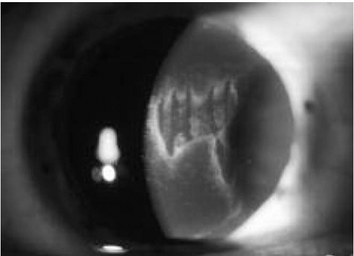 FIGURE 76-1. Button-hole formation with secondary scarring.(see color image) |
Flap Thickness, Head Plate Depth, and Hinge Location
Most microkeratomes designed for LASIK on the market today offer multiple footplate depths to produce a range of flap thickness. Factors that affect flap thickness are choice of head-plate depths, corneal thickness, preoperative refractive error, blade sharpness, blade length, translational speed across the cornea, and intraocular pressure.
The two most important patient factors to be considered in the choice of keratome head plates are corneal thickness and the preoperative refractive error. Preoperative pachymetry can be one of the biggest determinants of flap thickness (19,20). Thinner corneas tend to produce thinner flaps, and thicker corneas yield thicker flaps. Intraocular pressure can affect flap thickness as well, with lower pressures resulting in thinner flaps.
Another important factor to consider when choosing head plate depth is that the actual flap depth produced by different microkeratome heads of the same putative plate depth can vary substantially (20,21). In microkeratomes with replaceable depth plates, incorrect plate insertion can result in a deeper than intended cut with possible entry into the anterior chamber. Newer microkeratomes with a fixed depth plate are less likely to cause this complication.
Several factors influence the choice of the site of hinge placement including the risks of subsequent laser-associated
dry eye/epitheliopathy, relationship to astigmatic treatment, and reducing the risk of the flap truncating the ablation zone causing irregular astigmatism (22). Superior hinge placement has been proposed to have the advantages of vertical lid movement/upper lid compression maintaining flap position, distention, and centration. In contrast, corneal hypoesthesia lasts approximately 6 to 9 months, appearing to be greater with a superior than a nasal lamellar hinge (Fig. 76-2) in a prospective, randomized self-controlled trial, although there appears to be confounding reports of greater reduction in corneal sensation with a nasal hinge (23,24). In comparing hinge location and the effects on dry-eye symptoms/signs, superior hinge locations were associated with greater dry-eye symptoms (Fig. 76-3) (23).
dry eye/epitheliopathy, relationship to astigmatic treatment, and reducing the risk of the flap truncating the ablation zone causing irregular astigmatism (22). Superior hinge placement has been proposed to have the advantages of vertical lid movement/upper lid compression maintaining flap position, distention, and centration. In contrast, corneal hypoesthesia lasts approximately 6 to 9 months, appearing to be greater with a superior than a nasal lamellar hinge (Fig. 76-2) in a prospective, randomized self-controlled trial, although there appears to be confounding reports of greater reduction in corneal sensation with a nasal hinge (23,24). In comparing hinge location and the effects on dry-eye symptoms/signs, superior hinge locations were associated with greater dry-eye symptoms (Fig. 76-3) (23).
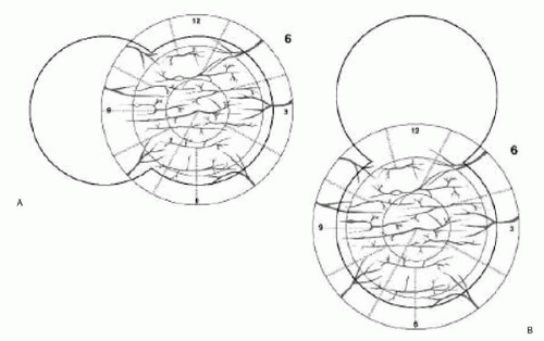 FIGURE 76-2. Nerve plexus of the cornea illustrating main innervations from nasal and temporal nerve branches demonstrating the potential effects of (A) nasal hinge and (B) superior hinge. (Courtesy of Eric D. Donnenfeld, M.D.) |
Residual Posterior Stromal Thickness
One of the most important factors to consider when choosing flap depth is the limitation imposed by the patient’s central corneal thickness and level of ametropia. It is not known exactly how much residual posterior stromal thickness (RPST) is required to prevent consecutive ectasia following LASIK (Fig. 76-4). An RPST of 250 μm is adequate in most cases, but there probably will be rare cases where ectasia can occur even with a RPST of greater than 250 μm (25,26). Thus, 250 μm and the flap thickness are subtracted from the lowest central pachymetry reading to determine how much ablation can be performed. The ablation depth can be approximated using the Munnerlyn formula (depth of ablation = diopters of correction × (ablation diameter)2/3). Blend zones and aspheric treatments as well as patient biomechanical response to treatment may alter these calculations (Fig. 76-5) (27). In corneas where the computation is close, the safest approach is to measure the residual thickness with ultrasonic pachymetry after the flap is lifted, eliminating the unknown factor of flap thickness, and alerting the surgeon to a flap that may be thicker than expected.
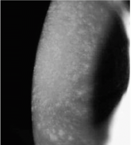 FIGURE 76-3. LASIK-induced corneal hypoesthesia with corneal punctate staining in a patient with nasal flap hinge. |
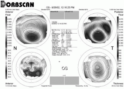 FIGURE 76-4. Orbscan of corneal ectasia secondary to myopic LASIK. The minimum post-LASIK corneal thickness is 428 μm. Calculated residual stromal bed was 300 μm after myopic ablation depth of 50 μm and presumed flap thickness of 180 μm. |
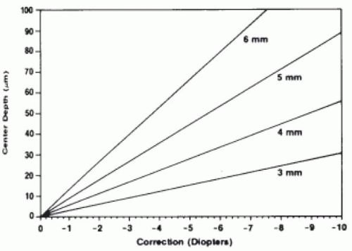 FIGURE 76-5. Maximum depth of cut for myopic correction. Each line represents the depth of cut on the optical axis for a given size of treatment. (From Munnerlyn CR, Koons SJ, Marshall J. Photorefractive keratectomy: a technique for laser refractive surgery. J Cataract Refract Surg 1988;14(1):49, with permission.) |
The decision to use a lower footplate setting, and thus a thinner flap, is probably only advantageous in a setting where there is a risk of exceeding the minimum safe residual stromal bed thickness of 250 μm. The decision to electively create a thinner flap without exceeding the parameters of minimum RPST is balanced by the disadvantages of a thin flap (potentially higher risk of flap folds/irregular astigmatism, buttonhole formation, increased difficulty handling thinner flaps/lifting flaps for enhancements, and less margin of error when cutting the flap) or using an alternative treatment such as LASEK, PRK, or phakic intraocular lens.
Vacuum Setting
Accurate and consistent flap creation is dependent on achieving and maintaining appropriate vacuum levels in any conventional microkeratome system. The suction system, therefore, should be checked prior to every procedure. Suction should be sufficient to raise the intraocular pressure to at least 65 mm Hg for most microkeratomes, with the newer systems allowing a degree of adjustment for variations in altitude. When using the Hansatome, the vacuum level required to achieve this intraocular pressure is approximately 20 to 27 inches Hg, depending on altitude. Lower pressures can produce thinner, less consistent or irregular flaps, whereas higher pressures increase the risk of chemosis, subconjunctival hemorrhages, and optic nerve injury. The intraocular pressure should be checked after the suction is activated to make certain that it is high enough to proceed with the microkeratome pass. Use of a pneumotonometer increases the accuracy of intraocular pressure measurements; if proper suction is not achieved or lost during the cut, the cut should not be performed or forward progress should be stopped immediately, as transection of the flap is possible. Newer microkeratomes have safety features that stop blade oscillation and forward progress if there is loss of suction.
Blade Selection, Control, and Variables
Blade assembly and inspection are critical to the success of the procedure. The surgeon should inspect the blade assembly, even if performed by trained personnel, in every case. An examination under the microscope should be done looking for smooth finish, good edge quality with no pitting, and no residue or metal shavings. Any blade irregularities can seriously affect flap quality and final visual outcome (Fig. 76-6). Blade quality can vary from unit to unit, and poor-quality blades should be rejected and replaced. It has been shown that dull blades produce thinner flaps and increase the risk of irregular flaps (28). Many centers utilize the same blade on both eyes of the same patient, but not more than this. Even in this usage it has been demonstrated that the second flap cut is somewhat thinner than the first (29).
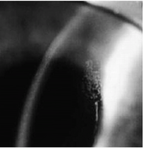 FIGURE 76-6. Postoperative photograph of an irregular flap secondary to a nick in the microkeratome blade. |
The microkeratome blade oscillates in a horizontal manner across the axis of travel by the keratome. The forward travel of the microkeratome along guided rails, track, or around a pinion is by either automated or manual means, i.e., mechanically driven or pushed forward by the surgeon. Blade entry angles vary from 25 to 30 degrees in the majority of keratomes. A steeper angle of blade entry enables the prescribed depth to be reached earlier, theoretically allowing easier alignment of the flap after the laser treatment. Horizontal blade oscillations of most keratomes vary between 12,000 and 18,000 oscillations/second. Translation, or forward progress, across the cornea may occur in a linear or rotational manner. Studies on the effects of translational speed and blade oscillations have reported that both have a significant effect on both flap thickness and smoothness of the stromal bed (30,31). Some commercially available units have independent engines for blade oscillation and head translation, allowing greater torque and independence of one from the other. An independent motor for blade oscillations allows blade movement to stop once the forward movement is complete.
FEMTOSECOND LASER
In contrast to the excimer laser with its ability to ablate tissue to a submicrometer level, approximately 0.3 μm per pulse, the relative inaccuracy of mechanical keratomes
(with a standard deviation of 20 to 30 μm) has led to the search for new technologies that could improve the precision and reproducibility of this surgical step in LASIK while reducing the complication rates of lamellar creation (32,33). These include water jet and short pulse lasers (34,35).
(with a standard deviation of 20 to 30 μm) has led to the search for new technologies that could improve the precision and reproducibility of this surgical step in LASIK while reducing the complication rates of lamellar creation (32,33). These include water jet and short pulse lasers (34,35).
With a short pulse of laser in the femtosecond (10−15 second) pulse length, the energy required to produce sufficient power (energy/time) for photodisruption is very small, such that the size of the cavitation bubbles and the secondary shockwave are minimal (36,37).
The femtosecond laser consists of a solid state neodymium (Nd):glass laser source and chirped pulse amplification to reach surgical energy levels. Pulses are generated at repetition rates of 3 to 5 kHz with each pulse of 500-femtosecond duration. The delivery system produces a beam focused to 3 to 5 μm size within the corneal stroma with each pulse estimated to remove 27 to 125 μm3 of stromal tissue (a sphere of diameter 3 to 5 μm). Laser delivery occurs via a scanning spot with an accuracy of approximately 1 μm (35). To perform a lamellar cut, the laser spots have to be placed in a contiguous spiral or raster pattern in any plane provided that treatment is started at the deepest level. Static gas bubbles occlude delivery of energy to a depth greater than the initial spot location. At present, the system that has received Food and Drug Administration (FDA) approval, Intralase Pulsion FS, requires control of the focal plane via a suction ring, pressure of 35 mm Hg, and flat applanation contact lens to achieve a claimed depth accuracy of 10 μm (35).
Potential advantages of the femtosecond laser include reduced flap complication rates, increased consistency of flap thickness and diameter, reduction in suction pressure required, and flexibility of hinge creation. The potential disadvantages include the longer procedure/vacuum time and required interval for “bubble” dispersion prior to LASIK treatment.
Published clinical trials using femto-LASIK microkeratomes report a flap thickness of 159 ± 8.5 μm (with a target of 160 μm). Time taken for flap creation was approximately 1 minute with flaps requiring 500,000 to 800,000 spots, with a superior hinge created. The same study reported standard deviations of flap diameter of ±0.1 mm for attempted 8.5- to 9.5-mm flap diameters. Target flap thickness achieved for an intended 160 μm thickness varied between ±10 μm for an 8.5-mm-diameter flap and ±13 μm for a 9.5-mm-diameter flap in porcine eyes (35).
In summary, the femtosecond laser appears to provide the means of providing accurate and reproducible lamellar incisions as well as further applications in corneal surgery (35). The proposed techniques of intrastromal refractive procedures require further investigation to determine both the feasible refractive treatment range and stability. Other applications of the femtosecond laser are discussed in Chapter 83.
EXCIMER LASER AND GUIDELINES FOR LASER SETTINGS
Stay updated, free articles. Join our Telegram channel

Full access? Get Clinical Tree


