Imaging Techniques of Fundus Autofluorescence
Steffen Schmitz-Valckenberg
Fred W. Fitzke
The imaging of fundus autofluorescence (AF) phenomena in vivo, as discussed in Chapter 1, was first demonstrated in the early days of fluorescein angiography, when preinjection fluorescence of optic disc drusen and optic disc hamartomas in tuberous sclerosis, and within lesions of Best vitelliform macular dystrophy was detected (1, 2, 3, 4). However, these observations were limited to a few patients with pathological accumulations of highly fluorescent material. By contrast, the naturally occurring intrinsic fluorescence of the ocular fundus is quite low—about 2 orders of magnitude lower than the background of a fluorescein angiogram at the most intense part of the dye transit (5). Absorption of excitation and emission light with partly additional generation of fluorescence by anatomical structures anterior to the retina further interferes with the detection of fundus AF. The main barrier is the crystalline lens, which has highly fluorescent characteristics in the short-wavelength range (excitation between 400 and 600 nm results in peak emission at 520 nm) (see also Chapter 3) (6). With increasing age and particularly the development of nuclear lens opacities, the fluorescence of the lens becomes even more prominent. Therefore, fundus AF imaging with a conventional fundus camera using the excitation and emission filters as applied for fluorescein angiography produces images with low contrast and high background noise in young persons (Fig. 5.1). In the elderly, the quality of the images drops even further and it becomes practically impossible to evaluate the distribution of fundus AF.
RECORDING FUNDUS AUTOFLUORESCENCE
To better record fundus AF, adjustments and modifications of existing camera systems or sophisticated new imaging devices are required. Such devices include the fundus spectrophotometer, the confocal scanning laser ophthalmoscope (cSLO), and the modified fundus camera.
Fundus Spectrophotometer
The fundus spectrophotometer developed by Delori and coworkers (5,7) was designed to measure and systematically analyze the excitation and emission spectra of the AF from small retinal areas (2 degrees diameter) of the fundus. By incorporating an image-intensifier-diode-array as detector, beam separation in the pupil, and confocal detection to minimize contribution of AF from the crystalline lens, this device allows absolute measurements of AF. Groundbreaking work by Delori et al. (5) demonstrated that lipofuscin is the dominant source of intrinsic fluorescence of the ocular fundus. However, the small field of view is not practical for recording fundus AF in large patient populations or in the clinical setting.
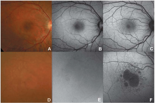 FIGURE 5.1. Comparison of fundus AF imaging with a conventional fundus camera and cSLO. (A) Fundus photograph of a 29-year-old subject with no eye disease and clear media shows good quality, with small retinal vessels and foveal reflex visible. (B) Fundus AF imaging with the conventional fundus camera using the filters as applied for fluorescein angiography and maximum flash intensity (300 J) in the same subject produces a noisy image with low contrast. The optic nerve head appears to be artificially bright, which may be caused by scattered excitation light and therefore would be attributable to pseudofluorescence. (C) Fundus AF imaging with the cSLO, in contrast, results in a clear image with high image contrast and high sensitivity. (D) The quality of the fundus color photograph of this patient with geographic atrophy secondary to age-related macular degeneration (AMD) is slightly impaired as a result of concomitant nuclear sclerosis of the lens. (E) Corresponding fundus AF image obtained with a conventional fundus camera using the excitation and emission filters used for fluorescein angiography. The image is hazy and no retinal details are visible. (F) Fundus AF image obtained using a cSLO. The quality of the AF image is better than that obtained with the fundus camera, and macular abnormalities, including a central area of atrophy, are observed. |
Confocal Scanning Laser Ophthalmoscopy
The use of a cSLO optimally addresses the limitations of the low intensity of the AF signal and the interference of the crystalline lens. It was used initially by von Rückmann and coworkers (8) in a clinical imaging system.
The cSLO projects a low-power laser beam on the retina that is swept across the fundus in a raster pattern (9). The intensity of the reflected light at each point, after it passes through the confocal pinhole, is registered by means of a detector and a two-dimensional image is subsequently generated. The use of confocal optics ensures that out-of-focus light (i.e., light originating outside the adjusted focal plane but within the light beam) is suppressed and thus the image contrast is enhanced. This suppression increases with distance from the focal plane, and signals from sources anterior to the retina, i.e., the lens or the cornea, are effectively reduced.
In contrast to the 2-degree discrete retinal field of the fundus spectrophotometer, the cSLO allows imaging over larger retinal areas. The standard image encompasses a retinal field of 30 degrees × 30 degrees. Additional lenses allow for imaging
of a 55-degree field or, using the composite mode, imaging over even larger retinal areas. To reduce background noise and enhance image contrast, a series of several single images is usually recorded (8,10, 11, 12, 13). For the final fundus AF image, a number of these frames (usually 4 to 32) are averaged and pixel values are normalized. Given the high sensitivity of the cSLO and the high frame rate of up to 16 frames per second, fundus AF imaging can be performed within seconds and at low excitation energies that are well below the maximum retinal irradiance limits of lasers established by the American National Standards Institute (14) and other international organizations.
of a 55-degree field or, using the composite mode, imaging over even larger retinal areas. To reduce background noise and enhance image contrast, a series of several single images is usually recorded (8,10, 11, 12, 13). For the final fundus AF image, a number of these frames (usually 4 to 32) are averaged and pixel values are normalized. Given the high sensitivity of the cSLO and the high frame rate of up to 16 frames per second, fundus AF imaging can be performed within seconds and at low excitation energies that are well below the maximum retinal irradiance limits of lasers established by the American National Standards Institute (14) and other international organizations.
Three different cSLOs have been widely used to obtain fundus AF images: the Heidelberg retina angiograph (HRA classic, HRA 2 and HRA Spectralis; Heidelberg Engineering, Dossenheim, Germany), the Rodenstock cSLO (RcSLO; Rodenstock, Weco, Düsseldorf, Germany), and the Zeiss prototype SM 30-4024 (ZcSLO; Zeiss, Oberkochen, Germany). For fundus AF imaging, all three use an excitation wavelength of 488 nm. Emitted light is detected above 500 nm for the HRA, above 515 nm for the RcSLO, and above 521 nm for the ZcSLO. Clinically useful fundus AF imaging has been reported with all three systems by several studies (8,10,12). A systematic comparison among the three systems by Bellmann and coworkers (15) in 2003 showed that both image contrast and image brightness were significantly higher with the ZcSLO and HRA classic compared to the RcSLO. Using a model eye, the highest background noise was measured with the ZcSLO and the lowest with the HRA classic. Since image contrast and brightness, and background noise are important indicators of image quality, Bellmann et al. (15) concluded that the observed differences might be of great importance when comparing fundus AF findings obtained with different imaging devices. Subsequent to their study, further developments led to the introduction of the HRA 2, which is currently the only commercially available cSLO for fundus AF imaging. This device allows real-time imaging, i.e., recording of the final mean and normalized image during acquisition. No time-consuming postacquisition processing of a movie is required. Thanks to an improved algorithm for automated image alignment to correct for eye movements during acquisition, a higher number of single frames can also be more easily captured, improving the signal-to-noise ratio and therefore possibly leading to better visualization of details. Recently, the combination of cSLO imaging with spectral-domain optical coherence tomography (OCT) in one instrument was made possible. This new imaging device enables simultaneous cSLO and OCT recordings, taking advantage of the registration of the fundus image and lateral eye movements by the cSLO system and synchronous topographic alignment to OCT scans. Several OCT scans can be averaged to reduce the background noise, and three-dimensional correlations of visible structural changes are possible.
MODIFIED FUNDUS CAMERA
Until recently, clinical applications of fundus AF imaging were limited to the cSLO, and in recent years the cSLO has gained increasing popularity and more widespread application. However, the major advantage of the cSLO—its sophisticated technical setup—also represents its major drawback: its considerable purchase and maintenance costs.
As mentioned above, fundus AF imaging with a conventional fundus camera operating in the same wavelength range as the cSLO has limitations due to the relatively low fundus AF signal, the absorption effects of the crystalline lens, and the nonconfocality, which makes the fundus camera prone to light scattering. Delori and coworkers
(16) described the possibility of obtaining fundus AF images using a modified fundus camera. This included the insertion of an aperture in the illumination optics of the camera to minimize the loss of contrast caused by light scattering and fluorescence from the crystalline lens. However, this modification also resulted in the restriction of the angle of view to a 13-degree-diameter circle; this, together with the complex design, is the likely reason why this setup has not been further pursued and used by other groups or in a clinical setting to date. Spaide (17) reported his elegant idea of modifying a commercially available fundus camera by simply moving the excitation and emission wavelengths for fundus AF imaging toward the red end of the spectrum to bypass the fluorescence of the lens. The theoretically inexpensive purchase of an additional filter set, together with the broad availability of the fundus camera, may represent an attractive alternative. Figure 5.2 illustrates the excitation and emission filters of the modified fundus camera as introduced by Spaide in comparison with the cSLO for fundus AF imaging. Note that Spaide recently developed an additional modification of the filters (here called “modified fundus camera 2” as opposed to “modified fundus camera 1” for the first modification). Currently, there is only one commercially available modified fundus camera for fundus AF imaging (Topcon TRC-50IX; Topcon, Paramus, NJ), based on the modification by Spaide (modified fundus camera 2). Because only the filters are altered in the modified fundus camera, the other technical details remain unchanged compared to the conventional fundus camera, including the angle of coverage (up to 50 degrees) and possible range of flash light intensities.
Currently, fundus AF imaging with the modified fundus camera is based on excitation by one single flash and the immediate capture of a single image. After acquisition, the image brightness and contrast values of this single image are manually adjusted to better visualize the individual distribution of fundus AF intensities.
Stay updated, free articles. Join our Telegram channel

Full access? Get Clinical Tree


