Since the introduction of functional endoscopic sinus surgery (FESS) in the United States in 1985, the information gained from imaging has proved imperative in understanding regional morphology and guidance of surgical procedures. More than 20 years later, the importance of imaging continues to be the anatomic detail afforded by this technology, the roadmap it provides in planning the surgery, and the morphologic detail it provides in recurrent disease. The latest development in CT technology, cone beam CT instrumentation, may change the way imaging of the nasal cavity and paranasal sinuses is performed in the future. These topics are discussed in this article.
Since the introduction of functional endoscopic sinus surgery (FESS) in the United States in 1985, the information gained from imaging of the nasal cavity and paranasal sinuses has proved imperative in understanding the regional morphology and guidance of surgical procedures. This regional morphology can vary significantly from patient to patient, and one quickly becomes aware of the fact that “no two noses are alike.”
Given the need for accurate and detailed display of the nasal cavity and paranasal sinus anatomy, the commonly used imaging technology in 1985, standard plain films and polytomography, was quickly replaced with CT. Coronal CT scans afforded improved resolution of the bony framework and the superimposed mucosa in addition to regional inflammatory pathology. The application of multiplanar reconstruction and then 3-D imaging subsequently provided a more 3-D understanding of the CT imaging data.
In 1991 a significant advance in the use of imaging information to help guide surgeons in the performance of FESS was accomplished with the introduction of image-guided surgery. The imaging data were used to register a patient’s location on the operating table with the patient’s imaging data in a computer, which then was able to show the location of the surgeon’s instruments in the operating field. Surgical accuracy and safety were significantly advanced.
More than 20 years after the introduction of FESS in the United States, the importance of imaging for surgeons continues to be the anatomic detail afforded by this technology, the roadmap it provides in planning the surgery, and the morphologic detail it provides in patients with recurrent disease after surgery. When considering the need to distinguish between various pathologic entities, MRI information can be added to CT information, because its soft tissue resolution is superior to CT.
The latest development in CT technology is cone beam CT (CBCT) instrumentation. This is a miniaturized CT scanner providing sufficient resolution to outline the maxillofacial bony architecture, and therefore the nasal cavity and paranasal sinus morphology. This scanner requires little space, is easy to operate, emits reduced radiation, and can easily fit in an office setting. This equipment may change the way imaging of the nasal cavity and paranasal sinuses will be performed in the future. These developments are the topics discussed in this article.
CT technique
Single-channel CT scanners use incremental or helical acquisition schemes for paranasal sinus examinations. Image acquisition in the coronal plane is preferred for optimal display of the anterior osteomeatal unit. The slice thickness should be 3 mm or less without interslice gap for optimal evaluation. Image acquisition in the coronal plane may require extension of the head, which may not be possible for some elderly patients and patients with airway problems or neck pain. Thin axial images can be reconstructed in the coronal plane for such patients.
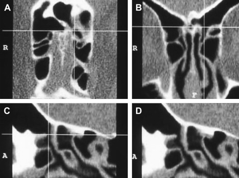
Multidetector CT (MDCT) scanners (also called multichannel or multislice CT scanners) use multiple rows of detectors that allow registration of multiple channels of data with one rotation of the x-ray tube. For example, a 16-slice MDCT scanner has a 16-fold capacity for collecting image data per x-ray tube rotation compared with a single-channel CT. Currently, 64-channel CT scanners are in routine clinical use. A head-to-toe CT scan with slices as thin as 0.2 mm can be obtained in 60 seconds. Recently, 312-channel scanners have been introduced that can image the same volume of tissue over and over again in a short time affording the physiologic studies of heart motion, myocardial perfusion, and brain perfusion. Thin slices permit isotropic data sets, in which the voxels (the smallest elements of a data set) are cubical. Isotropic voxels afford excellent reconstruction of images in essentially any desired plane without degradation of image quality. Isotropic imaging created a paradigm shift in CT imaging, no longer limited by the plane of acquisition. Data can be collected from a body part in any desired plane and 2-D images in any desired plane (multiplanar reconstruction) can be reconstructed ( Fig. 1 ). Real-time interactive manipulation of image data and 3-D reconstructions are made possible by high-performance workstations equipped with special software.
In the MDCT scanners, the x-ray beam is collimated to the thickness of the detector row making it a fan-shaped beam.
Flat panel–based/CBCT scanners were recently introduced for routine clinical use. Instead of rows of detectors, these use detectors arranged in a flat surface to capture the x-ray, which is not collimated to a fan shape but rather takes the form of a cone. These scanners have changed the image acquisition paradigm once again. Flat panel–based CT, instead of building the volume from individual slices, acquires the image data volume directly. This provides seamless volume images, which improve 2-D and 3-D reconstructions and model-building capability for presurgical evaluation.
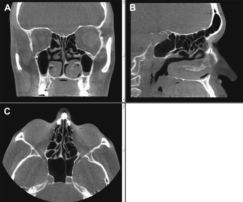
The x-ray source and the detector rotate around a fixed region of interest. The flat panel area detector permits a wider Z-axis coverage compared with a CT slice, allowing coverage of large areas in just one turn of the gantry, with enough data acquired to permit image reconstruction. A CBCT system ( Fig. 2 ) has some advantages over traditional MDCT, including decreased cost and radiation exposure. It also has inherent disadvantages, however, which include poor soft tissue contrast resolution due to noise from scatter radiation. Modern MDCT scanners have a contrast resolution of 1 Hounsfield unit (HU), which is 10 times better than that afforded by CBCT scanners. This remains the most significant barrier in widespread clinical use of CBCT.
In-office Considerations
The implementation of this technology in a rhinologic office would be more convenient for patients requiring the study, in that it would preclude the need to go through the effort of an additional office appointment. Although the immediate availability of the imaging data improves physician convenience, there are additional factors that need to be considered before adding this equipment to an ear, nose, and throat (ENT) office. The financial considerations regarding the equipment purchase are beyond the scope of this article, which addresses only technical issues.
Before a practice considers acquiring CBCT technology, perhaps the first issue to be considered is whether or not a facility is capable of housing the equipment. As CBCT emits radiation, there are radiation safety considerations, which must be evaluated on a state-by-state basis, as laws vary. Radiation monitoring is important to minimize exposure to the office staff and the general public, requiring proper structural shielding of the equipment to limit the scatter radiation beyond the space housing the equipment.
Most scanners permit the manipulation and viewing of the acquired data at the workstation, but if there is a desire to view images at other locations, a high-speed network must be in place. The amount of data acquired is often large and, depending on the volume of the practice, considerations must be made in regard to data storage. Accessibility of the images from multiple locations, such as office, operating room, and so forth, requires the use of a picture archiving and communications system and compatibility of this equipment with existing equipment should be considered.
It is also important to consider who will actually be acquiring the images. In most cases, a licensed CT technologist is needed to operate the equipment. Furthermore, who will interpret the imaging information? Although dental specialists may be well trained in the interpretation of the dental applications and otolaryngologists in sinus applications, what about nondental and nonsinus lesions that occasionally are present? The lack of soft tissue contrast, hence the inability to diagnose soft tissue lesions in the paranasal sinuses and orbits, is a significant limitation that has the potential to increase the vulnerability of practitioners. Liability issues regarding “missed” diagnoses need to be considered and need to be addressed in the implementation process of this diagnostic equipment. Lastly, but of equal importance, is the consideration of the frequency of use of the equipment. Having the equipment on the premises of an office makes it convenient to evaluate patients with chronic sinusitis with this technology. The physician-owner of the equipment needs to address possible queries regarding “overutilization” and “self-referral.” Strict guidelines regarding this issue should be established at the time of implementation of this technology to show a planned approach to the CT usage and therefore avoid possible criticisms that may be raised.
Radiation Considerations
To measure radiation emitted by MDCT scanners in a standardized fashion, CT dose-index (CTDI) and dose-length product have been developed. Approximate radiation equivalent doses related to diagnostic procedures are provided in Table 1 . The same general radiation principles are considered when comparing CBCT to MDCT but conventional metrics, such as CTDI and dose-length product, cannot be directly applied to CBCT because of altered beam geometry and differences in x-ray scatter profiles. In addition, the standard phantoms used do not capture the expanded Z-axis beam generated by CBCT that potentially results in significant underestimation of the dose associated with CBCT. An additional complicating factor is that the highest radiation dose in CBCT is at the center of the field, with diminished radiation toward the periphery. For these reasons, volumetric CTDI and dose-length product have been introduced to estimate radiation exposure with CBCT but as yet there is no universally applicable and standardized measure available. Nonetheless, actual dose measurements are obtained with volumetric indices using 18-cm phantoms with a few additional centimeters to incorporate scatter radiation that inevitably are encountered. Comparisons between CBCT and traditional MDCT have been performed ( Table 2 ). To maintain the same signal to noise at thinner slice sections, more radiation dose must be used. Published reports indicate that the effective dose varies for various full field-of-view (FOV) CBCT devices, ranging from 0.29 to 0.477 mSv, depending on the type and model of CBCT equipment, the duration of exposure, and FOV selected (see Table 2 ). Comparing these doses with multiples of a single panoramic dose or background equivalent radiation dose, CBCT provides an equivalent patient radiation dose of 5 to 74 times that of a single film–based panoramic x ray or 3 to 48 days of background radiation. The use of additional personal protection (thyroid collar) can substantially reduce the dose by up to 40%. Comparison with patient dose reported for maxillofacial/sinus imaging by MDCT, approximately 1.0 mSv, indicates that CBCT provides a dose reduction. It is not yet clear, however, whether or not the reported degree of dose reduction will be realized in routine clinical settings.
| Diagnostic Procedure | Effective Dose (mSv) | Number of Equivalent Posteroanterior Chest Radiographs for Equivalent Dose | Time Period for Equivalent Effective Dose from Natural Background Radiation |
|---|---|---|---|
| Posterioanterior chest radiograph | 0.02 | 1 | 2.4 days |
| Skull radiograph | 0.07 | 4 | 8.5 days |
| Lumbar spine | 1.30 | 65 | 158 days |
| Intravenous pyelogram | 2.50 | 125 | 304 days |
| Upper gastrointestinal series | 3.00 | 150 | 1.0 year |
| Barium enema | 7.00 | 350 | 2.3 years |
| CT head/sinuses | 2.00/0.96 | 100/48 | 243/100 + days |
| CT abdomen | 10.00 | 500 | 3.3 years |
Stay updated, free articles. Join our Telegram channel

Full access? Get Clinical Tree


