Correction of Astigmatism


Correction of Astigmatism


Edward S. Bennett

Kimberly A. Layfield

P. Douglas Becherer


The purpose of this chapter is to discuss methods of managing the astigmatic contact lens patient. These patients can often be challenging to the eye care practitioner; however, it is the ability to fit these people successfully that makes practice both enjoyable and profitable. The principles of residual and high astigmatic correction with gas-permeable (GP) lenses and astigmatic correction with soft toric lenses are reviewed.


▪ GAS-PERMEABLE CONTACT LENS APPLICATIONS


Residual Astigmatism

Residual astigmatism can be defined as the astigmatic refractive error present when a contact lens is placed on the eye to correct an existing ametropia. When a spherical lens is applied, the residual astigmatism is approximately equal to the difference between the corneal astigmatism and the refractive or total astigmatic error of the eye.

Residual astigmatism can be classified as either induced or physiologic. Induced residual astigmatism is associated with lens application and can be caused by lens warpage, flexure, decentration, or a toric anterior or posterior lens surface. This section of the chapter primarily addresses physiologic residual astigmatism, which commonly results from curvature refractive index differences of the posterior cornea and crystalline lens.


Calculated and Actual Residual Astigmatism

The calculated (or predicted) residual astigmatism (CRA) can be defined as the amount of astigmatism one would predict to result when a spherical GP lens is placed on the eye. It can be obtained directly by subtracting the patient’s central anterior corneal toricity (as measured by keratometry) from the total astigmatism of the eye at the plane of the cornea. The following examples illustrate the determination of CRA. In these examples, TRA refers to the total refractive astigmatism and ΔK refers to the difference between the keratometric readings of the two corneal meridians.


In Examples 4 and 5, the importance of vertexing the patient’s refraction to the corneal plane is quite apparent. In both cases if vertex distance was ignored, the calculated residual astigmatism would equal zero.

If a GP spherical lens of standard thickness (to minimize or eliminate the effects of flexure) is selected for a diagnostic fitting, the predicted spherocylindrical overrefraction (OR) can be calculated by using the following guidelines1:


  • List the spectacle correction (Rx) and keratometric readings.


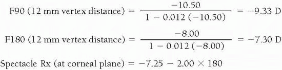
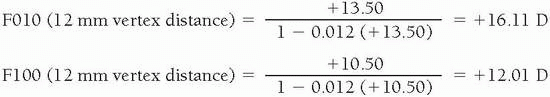
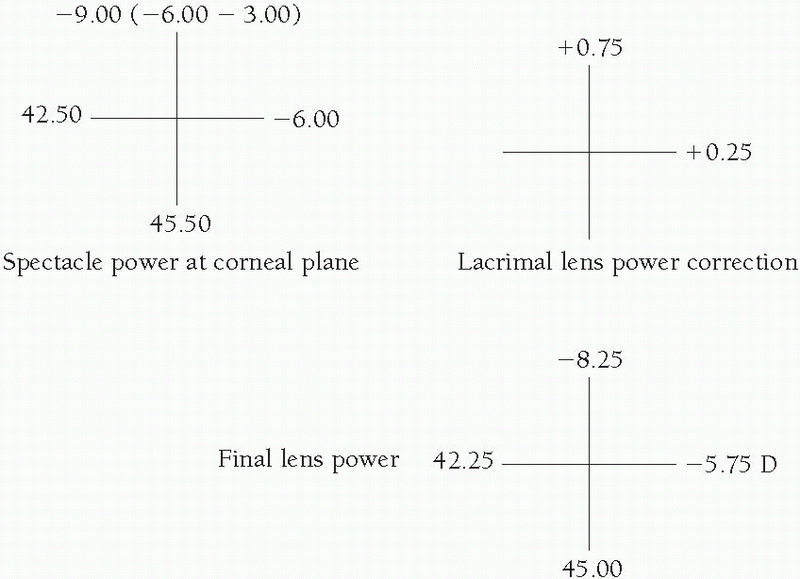
  • The effective power should be determined at the corneal plane (if indicated).


  • Determine the lacrimal lens power induced by the base curve radius (BCR) of the lens.


  • Add together the powers of the contact lens, lacrimal lens, and the difference between the keratometric readings of the principal corneal meridians.


  • With the following formula, subtract the value obtained in step 4 from the spectacle correction to obtain the overrefraction:

    Overrefraction (OR) = Spectacle Rx − [Contact Lens Power (CLP) + Lacrimal Lens Power (LLP) + ΔK]

The following example illustrates this principle:


Does the CRA correlate well with the residual astigmatism actually obtained after diagnostic lens application (i.e., actual residual astigmatism, or ARA)? There does appear to be some correlation, although often the ARA will be slightly less.2,3,4,5 In one study of over 400 eyes fitted with spherical GP lenses, the mean CRA was found to be −0.51 D ×090, whereas the mean ARA was equal to −0.23 D × 090.2 The difference between the CRA and ARA values could be caused by many factors, including inaccuracy of the keratometer for determining anterior corneal curvature (i.e., it evaluates only a few points on the paracentral cornea). In addition, examiner error in performing both refraction and keratometry could produce a difference between these two astigmatic values.

When a patient has refractive and keratometric cylinder axes that differ by >15 degrees, it can be assumed that the axes are unequal and the use of conventional crossed-cylinder
equations are necessary to determine the CRA. Because of the time involved, unless the appropriate tables or a computer-assisted contact lens design program is available, the use of a GP, spherical diagnostic lens for overrefraction to determine the residual astigmatism is advisable.


Methods of Correcting Residual Astigmatism

A GP contact lens may cause a reduction in visual acuity that is unacceptable to a patient because of the amount of residual astigmatism. This depends on the amount of residual astigmatism, the patient’s refractive error, and whether critical vision demands are common. Highly ametropic patients may be able to tolerate a higher amount of residual cylinder than low ametropes. Therefore, individual variance is determined by the amount of residual astigmatism necessary to contraindicate the use of a spherical GP lens; however, patients exhibiting >0.75 D often experience subjectively compromised vision. Methods of correcting residual astigmatism include spherical GP lenses, spherical soft lenses, soft toric lenses, and front surface toric GP lenses.


Spherical Gas-Permeable Lenses:

Spherical GP lenses can be successfully fitted to patients exhibiting residual astigmatism if any one of the following conditions exists:

1. ARA differs in amount from CRA. For example, you may predict a CRA of −1.00 × 090, but your overrefraction results in a value of −0.50 × 090. Rechecking keratometry or the subjective refraction may determine where the error was made. However, the most important factor is to never allow the CRA to prevent spherical GP lens application because of the possibility of obtaining a lower ARA value.

2. The lens can flex on the eye to reduce residual astigmatism. In most cases, flexure or bending of a GP lens on the eye will increase the existent residual astigmatism. However, there is one case in which flexure will actually reduce or totally correct residual astigmatism. It has been found that when the corneal toricity is with-the-rule and the residual astigmatism is against-the-rule, a thin spherical GP lens will flex and reduce the amount of residual astigmatism.6 This is illustrated in the following example:


A thin lens can flex between 0.25 to 0.50 D to correct some of this residual astigmatic error.6,7 The use of a GP lens with high oxygen permeability (Dk) in a thin, large-diameter design fitted “steeper than K” (e.g., the Menicon Z thin design) should, in theory, correct even a greater amount of residual astigmatism.

3. The demand on critical vision is low.

4. The patient’s visual acuity is not decreased to an unacceptable level.


Spherical Soft Lenses:

There is one situation in which a spherical soft lens would definitely be indicated. If very little or no refractive astigmatism is present in the patient’s spectacle correction,
a spherical soft lens should provide acceptable visual acuity. This is demonstrated in Example 8.


The other advantage of spherical soft lens use is the avoidance of a more complicated and expensive lens design.


Soft Toric Lenses:

The most common reason for the rapid decline in front surface toric GP lenses for correction of residual astigmatism is the optical quality, parameter availability, and disposability of soft toric lenses. With few exceptions, patients with ≥0.75 D of ARA can be fitted successfully into soft torics. The availability of large diagnostic sets incorporating numerous astigmatic corrections has also made this an easy option for fitting patients. The following examples illustrate representative applications for soft toric lenses in patients with a high amount of residual astigmatism:


In Examples 9 and 10, these patients exhibited no and high corneal astigmatism, respectively; however, they were both good candidates for soft toric lenses. Soft toric lenses are most successful when the refractive cylinder is between −0.75 D and −2.00 D and the cylinder axis is not oblique. The reasons for this are fourfold:


  • Most soft toric lenses are available in these parameters; higher-cylinder-power custom lenses are available at slightly more—to much greater—expense.


  • Most diagnostic sets and inventories are in these parameters.


  • In high refractive astigmatism, rotation of the lens with the blink may reduce visual acuity.


  • Oblique cylinder axes tend to result in greater lid effect on the lens edge; therefore, rotational instability is possible.


Front Surface Toric Gas-Permeable Lenses:

Application of the patient’s residual astigmatic correction onto the front of the GP lens surface was, until the introduction of soft toric lenses, the most common method of correcting this problem. It is still a recommended option in some cases, including patients who desire or benefit visually from a GP lens and those who have experienced soft lens-induced complications [i.e., edema, giant papillary conjunctivitis (GPC)]. Three stabilization methods have been used: (a) prism ballast, (b) prism ballast and truncation, and (c) periballast.

1. Prism ballast. Prism ballast can be incorporated into a GP lens to allow the patient’s residual cylinder to be ground onto the front surface of the lens. The purpose of the prism is to stabilize the lens from possible rotational movement induced by the action of the lids. It is recommended when patients have lower lids at or below the lower limbus, when large palpebral apertures with loose lids are present, and whenever discomfort is experienced with truncated, prism-ballasted lens designs.8

The amount of prism to be incorporated into the lens design is the minimum amount that produces stabilization and is dependent on lens power. An amount equal to 0.75 to 1 Δ for moderate and high minus lenses and 1.25 to 1.5 Δ for low minus and plus lenses has been recommended.9 A greater amount of prism is indicated with plus power lenses because of the thinner edge present in these designs.

Because of the greater center thickness (CT) of these lenses in comparison to spherical designs, a high-Dk lens material (>50) is recommended. A minimum overall diameter (OAD) of 8.8 mm is recommended, both to incorporate the prism effectively and help offset the possible effects of flare from a heavier, potentially inferiorly decentering lens design. To estimate the center thickness of a prism-ballasted lens, the following equation can be used9:

Center thickness × 100 = Prismatic power × Overall diameter

Therefore, if 1 Δ were used for stabilizing a 9.0-mm OAD, 0.09 mm would need to be added to a conventional spherical lens design of the same power (more plus meridian) to obtain an estimate of the CT in prism-ballasted form. If the conventional spherical CT for the lens power in the most plus meridian is 0.15 mm, in prism-ballasted form the CT would equal 0.15 + 0.09, or 0.24 mm.

If a diagnostic fitting set is present, a slightly “steeper than K” lens should be selected. As the center of gravity tends to be more anterior and the mass of these lenses tends to defy gravity somewhat, a plus tear film centrally should assist with centration. If the lens is riding inferiorly with little or no movement after the blink, a minus carrier should be indicated in the final order. A well-fitted lens will move slightly superiorly with the blink but with little or no rotation (i.e., a direct vertical movement).10 Evaluating the amount of lens rotation with the blink is very important. This effect will vary as a result of such factors as the lid configuration, location, tightness, and forcefulness of the blink. As a result of the natural alignment or symmetry of the superior lid, there is a tendency for the lid to rotate nasally or excyclorotate. Therefore, the presence of tight lids or a forceful blink may contraindicate a front surface toric design. Assuming the base of the prism is dotted on the diagnostic lens, the amount of rotation can be evaluated in several ways, including the following:


  • Trial frame. The patient can also wear a trial frame in combination with a low-power cylinder trial lens having hash marks for judgement of rotation (Fig. 14.1). The marks on the spectacle trial lens can be aligned with both the prism base and the optical section beam, and the degree reading can be read directly from the trial frame.


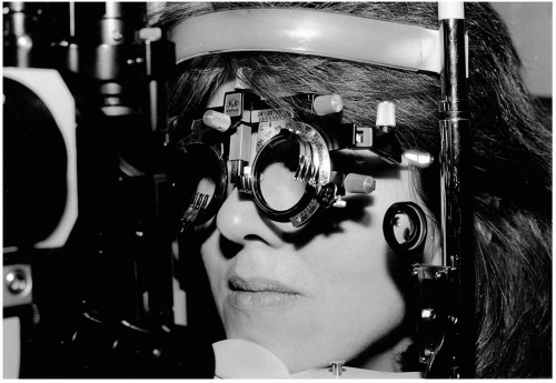
    ▪ FLGURE 14.1 Trial frame use with trial lens and hash marks to estimate toric lens rotation.


  • Slit-lamp beam rotation. Many of the slit lamps in use today allow the practitioner to rotate the optical section to align with the position of the prism base. The amount of rotation can be read directly from a scale on the slit lamp.


  • “Guesstimate.” The most commonly used (and convenient) method is simply to estimate the amount of rotation with the blink. Because it is very easy to underestimate the amount of rotation, always think of the lens as a clock, with each hour equivalent to 30 degrees. If the prism base appears to be at approximately 6:30 (not 6 o’clock), the prism base has rotated 15 degrees. The importance of proper evaluation of rotational amount and stability is discussed further in the section of this chapter on soft toric lenses.

After the amount of rotation has been determined by one of the aforementioned methods, the contact lens powers must be adjusted accordingly. If, as you observe the lens, the right lens rotates 15 degrees nasally (to the observer’s right) and the left lens rotates 15 degrees nasally (to the observer’s left), then the LARS (left add, right subtract) principle is used (Fig. 14.2). In this case the axis of the final cylinder power of the right lens is decreased by 15 degrees, while the cylinder axis of the left lens is increased 15 degrees. On the average, prism-ballasted lenses tend to rotate 10 to 15 degrees nasally.

When a desirable lens-to-cornea fitting relationship has been achieved and an overrefraction performed through the ballasted sphere, the lenses can be ordered. If a diagnostic fitting set is not available (as is often the case), an overrefraction over the best-fitting spherical lenses will assist in determining the final lens powers. The calculations required to arrive at the final parameters are illustrated in the following example1:


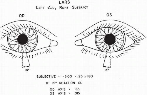
▪ FIGURE 14.2 The LARS (left add, right subtract) principle.

The LLP can be obtained by subtracting the combined powers of the contact lens and the overrefraction from the spectacle correction.

The values obtained in the overrefractions above actually equal the predicted values. These can be obtained by performing the following calculations:


OD


OS


LLP


= Spectacle Rx − (CLP + OR)


= [−1.50 − 1.00 × 090] −


[−2.50 − 1.25 × 090]


[(−3.00) + (+) 1.25 − 1.50


− [(−3.00) + (+)0.25 − 1.00


× 090]


× 090]


= [−1.50 − 1.00 × 090]


[−2.50 − 1.25 × 090]


− [(−)1.75 − 1.50 × 090]


− [(−)2.75 − 1.00 × 090]


= +0.25 + 0.50 × 090


+0.25 − 0.25 + 090


The contact lens power can be derived simply by subtracting the LLP from the spectacle correction:


OD


OS


CLP


= Spectacle Rx − LLP


= [−1.50 − 1.00 × 090]


[−2.50 − 1.25 × 090]


= [+0.25 + 0.50 × 090]


− (+)0.25 − 0.25 × 090


= −1.75 − 1.50 × 090


−2.75 − 1.00 × 090


As the cylinder will be ground on the front surface of the lens in plus cylinder form, the contact lens powers are transposed to:


OD


OS


−3.25 + 1.50 × 180


−3.75 + 1.00 × 180


As compensation for lens rotation is often desired, this could become:


OD


OS


−3.25 + 1.50 × 165


−3.75 + 1.00 × 015


The contact lens order could be written as follows:


Parameter


OD


OS


BCR


43.50 (7.76)


43.50 (7.76)


CLP


−3.25 + 1.50 × 165


−3.75 + 1.00 × 015


OAD


9.0


9.0


OZD


7.8


7.8


SCR/W (=BCR + 1 mm)


8.8/.3


8.8/.3


PCR/W (=SCR + 2 mm)


10.8/.3


10.8/.3


CT


0.26


0.25


Prism


1Δ, double dot base


1Δ, dot base


Material


Fluoroperm 60


Fluoroperm 60


Add. information


Minus carrier


Minus carrier


2. Prism ballast and truncation. In most cases in which a front toric GP lens is desirable, the lens of choice is a prism-ballasted truncated design. The addition of truncation assists in providing good rotational stability.

Most of the design and fitting information provided for prism ballast-only designs also pertains to lenses that incorporate prism ballast. The primary differences pertain to OAD, prism, and the shape of the inferior edge. Typically, vertical diameters are 8.7 to 9.2 mm, with horizontal diameters usually 0.4 to 0.5 mm larger.8 Truncating a prism-ballasted lens reduces the ballast for minus lenses and increases it for plus lenses. Therefore, especially in high minus powers, the need for more prism ballast is imperative to maintain the truncation in contact with the lower lid; an amount equal to 1.25 to 1.5 Δ would be recommended, whereas a smaller amount is indicated for low minus and plus power lenses. Finally, the shape of the truncation is quite important. As the truncation should rest evenly against the lower lid, the edge should be flat to increase the distribution of lens pressure across as much of the lid as possible.8 Anterior tapering of the lens edge may result in the truncation slipping under the lower lid; posterior edge tapering may result in subjective discomfort. Because of the typical nasal rotation of the base, ordering the truncation at approximately 15 degrees temporal to the base-apex line would be recommended. Referring back to Example 11, the order of a prismballasted truncated design might be similar to the following:


Parameter


OD


OS


Base curve radius


43.50 (7.76)


43.50 (7.76)


CLP


−3.25 + 1.50 × 165


−3.75 + 1.00 × 015


OAD


9.4/8.9


9.4/8.9


OZD


7.8 (decentered 0.5 mm) up


7.8 (same as OD)


SCR/W


8.8/0.3


8.8/0.3


PCR/W


10.8/0.3


10.8/0.3


CT


0.26


0.25


Prism


1.25 Δ


1.25 Δ


Material


Fluoroperm 60


Fluoroperm 60


Add. information


Double dot base


Dot base


Truncation 15° temp OU


The above examples assumed that diagnostic lenses were unavailable. Obviously, the success rate would be higher if diagnostic lenses were used. A recommended diagnostic set is provided in Table 14.1.

Prism-ballasted, front surface toric lens designs, both truncated and nontruncated, are associated with some problems that limit their use. These include the following1:


  • Vision is blurred.


  • Discomfort results from prism, truncation, or both.


  • Quality control is poor.


  • 4. Inferior decentration causes flare and possibly corneal desiccation.


  • It is not possible to modify the front surface.


  • If unilateral, asthenopia can result from a vertical imbalance although low amounts of prism (i.e., 0.75 − 1 Δ) can usually be tolerated.


  • Edema can develop if a low-Dk GP lens material is used.

Verification of front surface toric lenses is straightforward. The back surface of the lens is placed against the lens stop of the lensometer and is rotated until the position of the target image indicates prism base down (axis = 90 degrees). If, for example, the left lens cylinder was ordered at axis 105, the base of the prism should be rotated nasally 15 degrees to obtain the power in that meridian. The lens is then rotated 90 degrees to obtain the power in the other
meridian. The cylinder power of the lens is the same on the eye as in air when measured with the lensometer, as the cylinder is on the front surface only. If the lens was ordered with the power −3.25 +1.25 × 075, this should be the power read with the lensometer.


TABLE 14.1 CIRCULAR PRISM-BALLASTED TRIAL LENS SET (10 LENSES)


BASE CURVE


OAD/OZD


CLP


SCR/W


PCR/W


1. 40.50 (8.33)


9.2/8.0


−3.00


9.30/0.3


11.30/0.3


2. 41.50 (8.13)


9.2/8.0


−3.00


9.10/0.3


11.10/0.3


3. 42.00 (8.04)


9.2/8.0


−3.00


9.00/0.3


11.00/0.3


4. 42.50 (7.94)


9.0/7.8


−3.00


8.90/0.3


10.90/0.3


5. 43.00 (7.85)


9.0/7.8


−3.00


8.90/0.3


10.90/0.3


6. 43.50 (7.76)


9.0/7.8


−3.00


8.80/0.3


10.80/0.3


7. 44.00 (7.67)


9.0/7.8


−3.00


8.70/0.3


10.70/0.3


8. 44.50 (7.58)


8.8/7.8


−3.00


8.60/0.3


10.60/0.3


9. 45.00 (7.50)


8.8/7.8


−3.00


8.50/0.3


10.50/0.3


10. 46.00 (7.34)


8.8/7.8


−3.00


8.30/0.3


10.30/0.3


CLP, contact lens power; OAD, overall diameter; OZD, optical zone diameter; PCR/W, peripheral curve radius/width; SCR/W, secondary curve radius/width.


3. Periballast. A periballasted lens design is cut in lenticular form with a high minus carrier. Two forms of this lens design are available. In one form, the final lens is cut with no flange at the top and with the entire 1.0 to 1.3 mm of flange left at the bottom to achieve the ballast. In the other form, the lens is manufactured such that a small amount of flange remains at the top to provide a minus carrier effect.

A periballast does reduce some of the prism ballast-induced problems. The advantages include better optical quality, a thinner design, and no vertical imbalance. However, it is rarely used because of the rotational instability and flange-induced discomfort.


High Astigmatism

The correction of high astigmatic error, defined as ≥2.50 D of corneal astigmatism, is quite different from correction of residual astigmatic error. In most cases, the selection of a carefully designed spherical or bitoric design will be successful with these patients. The latter design alternative is most often recommended, and these designs are easy to fit and evaluate. Other alternatives include aspheric designs, toric soft lenses, and back surface toric GP lenses.


Spherical Gas-Permeable Lenses

Although the benefits of a spherical design in high astigmatism include the use of an uncomplicated lens design and less expense, the selection of this alternative will, in most cases, eventually result in failure because of such problems as decentration-induced symptoms of visual flare, corneal desiccation resulting from excessive peripheral clearance, flexure-induced fluctuation in visual acuity, and lens rocking resulting in corneal staining.10 In addition, although good centration is possible to achieve regardless of the amount of corneal astigmatism, these lenses will, as a result of poor corneal alignment, apply excessive pressure (i.e., bearing zones) against the cornea, possibly resulting in corneal distortion.11 This condition is accelerated if poor centration is present.12

In many cases, it is not a bad idea to use a spherical lens as the initial diagnostic lens and evaluate vision, corneal alignment, and centration. A relatively low-Dk material (i.e., 25-50) should be selected to minimize flexure and facilitate manufacture. The BCR should be about one-third of the difference “steeper than K” to achieve a well-centered intrapalpebral lens-to-cornea fitting relationship. The CT in minus lens powers should be 0.02 to 0.04 mm thicker than with low astigmatic patients to minimize flexure. Overkeratometry should also be performed to rule out flexure. If toricity >0.50 D exists with overkeratometry, either a flatter BCR or a bitoric lens design should be considered.


Aspheric Designs

An aspheric design may provide better centration and a more uniform fluorescein pattern than a spherical lens design. In particular, designs with an elliptic back surface (i.e., the progressive and the so-called “biaspheric” designs) have been shown to exhibit good centration in patients having 2 to 3 D of corneal astigmatism (Fig. 14.3).13 However, to minimize symptoms of visual flare, good centration is imperative with these designs.


Soft Toric

Improvements in quality control, enhanced quality of vision, and greater oxygen transmissibility currently make this modality an option to consider when a high astigmatic patient with no evidence of corneal distortion is strongly motivated toward soft lens wear.14 In addition,
numerous companies manufacture custom soft toric lenses in practically any axis and power, and improvements in edge designs have resulted in better subjective comfort than was attained with previous-generation designs. Finally, computer-assisted lens design programs are available that are especially beneficial in cross-cylinder situations and currently are being used by both practitioners and manufacturers.15 This type of program is capable of providing a recommended cylinder axis and power based on the patient’s refractive data, the diagnostic lens parameters, and the amount of rotation on the eye.


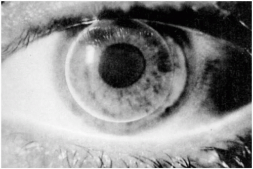
▪ FIGURE 14.3 An aspheric lens (Boston Envision) providing good centration and a less obvious “dumbbell-shaped” fluorescein pattern than present with a spherical design.

Excellent quality control is imperative with these lenses, and they should also be stable on the eye; rotation of only a few degrees can significantly affect visual performance, especially with patients having more than 3 D of corneal astigmatism. If corneal distortion or irregular astigmatism is present, a much better visual result can be attained with the selection of a GP lens. Manufacturers’ claims of success and accuracy may also be erroneous; therefore, it’s important to consider toric soft lenses when the patient is motivated, astigmatism is regular, and the need for critical distance vision is not great.


Back Surface Toric

A back surface toric lens design has the advantage of providing greater alignment of the posterior lens surface to the cornea; therefore, better centration is present. In addition, problems such as flexure, lens rocking, and flare are minimized.

There are numerous philosophies on how to determine the base curve radii for any posterior surface (i.e., back surface or bitoric designs). The Mandell-Moore philosophy for determining the base curve radii is provided in Table 14.2.16 To assist in achieving alignment between lens and cornea, toric peripheral curves may be beneficial.17 To determine the specific peripheral curve radii to select, the following philosophy can be used:


  • Secondary curve radii (SCR) = 1.0 mm flatter than the base curve radii [e.g., if the base curve radii are 41 D (8.23 mm) and 44 D (7.67 mm), the SCR would be 9.23/8.67 mm or rounded off to 9.2/8.7 mm].


  • Peripheral curve radii (PCR) = 3.0 mm flatter than the BCRs; in the above case they would be equal to 11.2/10.7 mm.

If a spherical periphery is desired, simply add 1.0 mm to the average BCR to determine the SCR and add 3.0 mm to determine the PCR. In the above example, the average between 41 D and 44 D equals 42.50 D (7.94 mm); the SCR would equal (approximately) 8.9 mm and the PCR would equal 10.9 mm.


TABLE 14.2 MANDELL-MOORE FIT FACTOR


CORNEAL CYL


FIT FLAT MERIDIAN


FIT STEEP MERIDIAN


2.0 D


On K


0.50 D Flatter


2.5 D


0.25 D Flatter


0.50 D Flatter


3.0 D


0.25 D Flatter


0.75 D Flatter


3.5 D


0.25 D Flatter


0.75 D Flatter


4.0 D


0.25 D Flatter


0.75 D Flatter


5.0 D


0.25 D Flatter


0.75 D Flatter


From Mandell RB, Moore CF. A bitoric lens guide that really is simple. Contact Lens Spectrum 1988;3(11):83-85.


When determining the base curve radii, the tear layer power will result in a change in power. To determine these values, Sarver’s formula can be used18:

Fs = Ff + Kf − Ks

where

Fs = the back vertex power of the contact lens in the steeper principal meridian (in air)

Ff = the back vertex power of the contact lens in the flatter principal meridian (in air)

Ks = the BCR of the contact lens in the steeper principal meridian

Kf = the BCR of the contact lens in the flatter principal meridian

All of this information can be incorporated into the following example:


A spherical diagnostic lens with a BCR of 41.50 D was attempted. However, this lens resulted in inferior decentration and some flexure-induced uncorrected corneal astigmatism confirmed by toric readings by keratometry performed over the lenses. A back surface toric lens design, using the Mandell-Moore base curve philosophy, is then ordered. The parameters can be obtained from the following:


  • Kf = 40.50 + (−)0.25 = 40.25 D


  • Ks = 44.50 − 0.75 = 43.75 D


  • Ff = +0.50 + (0.25)(LLP) = +0.75 D


  • Fs = +0.75 + (40.25 − 43.75) = −2.75 D

The peripheral curves can be determined as follows:


SCR = 8.00 mm (rounded off from 8.04) + 1.00 = 9.00 mm

PCR = 8.00 + 3.00 = 11.00 mm


Final order (empirical):


BCR


Power


SCR/W


PCR/W


OAD


40.25/43.75


+0.75


9.00/.3


11.00/.3


9.2


(8.38)(7.71)


Unfortunately, the great majority of high astigmatic patients would not be able to achieve optimum visual acuity from a back surface toric design because of the problem of induced cylinder. A back surface toric GP contact lens in situ induces a cylinder in the optical system (contact lens-fluid lens) designed to correct the ametropia. The minus cylinder is the result of the difference between the refractive index of the contact lens (n = 1.44-1.49 in most cases; 1.49 will be used here) and the index of the tear lens (n = 1.336). The exact amount would be 0.456 times the back surface toricity. The minus cylinder axis will lie along the flatter principal meridian of the toric back surface of the contact lens. This induced cylinder rarely corrects and sometimes compounds the residual astigmatism.

The following contact lens conversion factors are important when determining the changes in power induced by a toric back surface contact lens.


  • From back surface lens toricity (measured with the radiuscope) to contact lens cylinder power in air (measured with the lensometer)—multiply by 1.452 (or approximately 1.5).


  • From back surface lens toricity (measured with the radiuscope) to the contact lens cylinder power measured in fluid (on the eye or induced)—multiply by 0.456 (or approximately one-half).


  • From contact lens cylinder power in air (measured with the lensometer) to the contact lens cylinder power in fluid (on the eye or induced)—multiply by 0.314 (or approximately one-third).


  • From the contact lens cylinder power in fluid (on the eye or induced) to the contact lens cylinder power in air (measured with the lensometer)—multiply by 3.19 (or approximately 3).

Essentially, this concept can be simplified to a 1:2:3 principle (Fig. 14.4). This would represent a fractional component by which if one component is known, the other two can be easily determined. If “2” equals the amount of base curve toricity verified with the radiuscope, “1” equals 1 divided by 2 or one-half the base curve toricity; “3” equals both three times the “1” value or 3/2 times the base curve toricity. If the base curve toricity equals 3 D, the induced cylinder predicted with lens wear is one-half this value or 1.5 D; the value verified with a lensometer is 4.5 D or 3/2 times the radiuscope value.

Referring back to Example 12, the amount of induced astigmatism would equal approximately 0.5 × ΔK (back surface or −3.50 × 180) = −1.75 × 180. A plus correcting cylinder of the same amount and axis is applied to the front surface; therefore, in this case, +1.75 D × 180 is the front surface cylinder power. This will result in a power of -3.50 × 180 while creating a spherical power effect (i.e., the lens can rotate on the eye without affecting vision); this will be discussed later in this section of the chapter.

The other factor to consider when verifying a back surface toric lens is that because the induced astigmatism is not corrected, when the cylinder power is verified with a lensometer, a value equal to approximately 1.5 times the back surface toricity (radiuscope cylinder) will be read. In the previous example, the amount of cylinder power recorded with a lensometer is -3.50 × 1.5 = −5.25 D × 180. This is a key factor when a back surface toric is differentiated from a bitoric lens because a bitoric design with the induced cylinder corrected on the front surface (unless a significant residual astigmatism is also being incorporated into the lens) will verify with a similar cylinder for both the radiuscope and the lensometer.

To summarize this discussion, it is apparent that to obtain both good centration and good visual acuity, a bitoric lens is indicated. There is one situation in which a back surface toric design would provide the preferable vision correction. This design is the lens of choice when
the corneal toricity is against-the-rule and the residual astigmatism is approximately 0.5 times the amount of back surface toricity of the lens (as measured with the radiuscope).


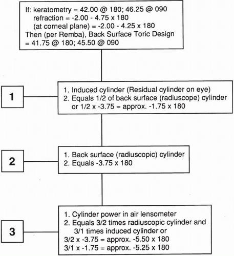
▪ FIGURE 14.4 The 1:2:3 principle.


Bitoric Design

In most cases of high corneal astigmatism, a bitoric lens design should be used. The benefits of centration (Fig. 14.5) and, if the lenses are well designed and manufactured, satisfactory visual acuity are present with this option.

It was mentioned earlier that if the induced astigmatism that was created as a result of the toric anterior tear layer is corrected, a spherical power effect is created. In other words, if this front surface correction is ground onto the lens in the correct meridian relative to the principal meridian of the base curve, lens rotation will not alter the correction and the bitoric lens will provide a spherical effect when correcting only for the induced astigmatism.19,20 This is
shown in Figure 14.6 in which the extreme case of 90-degree rotation is provided. It is shown that the tear layer will compensate, and the front surface cylinder correction will still equal the new cylinder and axis of the induced cylinder.


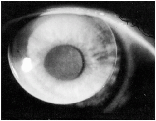
▪ FIGURE 14.5 A well-centered bitoric lens on a highly astigmatic cornea.


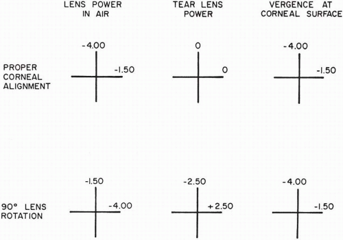
▪ FIGURE 14.6 The principle of spherical power effect.


Fitting Methods:

A misperception of bitoric lenses is that they are very challenging to fit. However, this has not been substantiated by recent research.21,22 In a survey of the Diplomates of the Cornea and Contact Lens Section of the American Academy of Optometry (AAO), approximately 90% responded that bitoric GP lenses varied from acceptable to very easy to fit.22 These lenses are fitted either empirically or via a bitoric diagnostic set.


Empirical Methods:

The lens powers and base curve radii of any back surface or bitoric lens design can be determined by several methods, including the previously demonstrated computational method.10 Example 13 shows how these values can be determined for a bitoric design using both computational and optical cross methods:


It is important for the laboratory to understand that these are the values that should be verified with the lensometer. Therefore, the powers should represent compensated values with the induced cylinder correction on the front surface. In this case, approximately 0.50 × −2.50 (back surface cylinder) = −1.25 D × 180. + 1.25 D × 180 will need to be added to the front surface to arrive at the final lens powers of −5.75/-8.25.

As the optical cross method illustrates, it is not necessary to use a formula to determine the final lens powers. Essentially, a bitoric design can be considered as two spherical designs when tear lens power calculations are performed. In this example, a BCR was selected that was 0.25 D “flatter than K” in the horizontal meridian. Using the SAM-FAP philosophy (i.e., steep add minus/flat add plus), the power in the meridian becomes 0.25 D more plus or -5.75 D. In the steep meridian, a BCR was selected that was 0.75 D “flatter than K” in the steep meridian; therefore, the final lens power becomes 0.75 D more plus or −8.25 D.

3. Mandell-Moore Bitoric Lens Guide

Another computational method for determining the bitoric lens specifications is the Mandell-Moore bitoric lens guide.16 This is a simple reference guide in which the keratometric and refraction information is entered and the final values are derived using the recommended base curve radii. This is an excellent empirical method for determining powers and base curve radii in which it is not necessary to compute lacrimal lens effects. It has also been found to result in a comparable success rate when compared with diagnostic fitting of bitoric lenses.23 An example of this method is provided in Figure 14.7. The form is downloadable from the GP Lens Institute website (www.gpli.info). There is also a calculator to perform the calculations on this website.


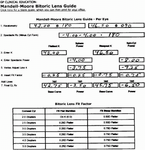
▪ FIGURE 14.7 Mandell-Moore bitoric lens guide.


Spherical Power Effect Bitoric Diagnostic Lenses:

The use of bitoric diagnostic lenses is the preferable method of fitting these patients. Most Contact Lens Manufacturers Association (CLMA) member laboratories have bitoric diagnostic fitting sets available for loaner use as well as for purchase. Excellent success rates have been reported by fitting high astigmatic patients by using the Polycon II spherical power effect (SPE) bitoric diagnostic lenses (Ciba Vision Corp.).24,25,26 In fact, in the aforementioned survey of AAO Diplomates, the Mandell-Moore Empirical Fitting Guide was the most commonly used empirical fitting method and the Polycon II SPE design was the most commonly used bitoric diagnostic fitting set.21 This concept makes fitting bitoric designs as simple as fitting spherical lens designs, and many patients obtain visual acuity equal to or better than that achieved with their optimum spectacle correction.

Ten lens diagnostic sets are available with 2 D (recommended for <3 D of corneal astigmatism), 3 D (recommended for 3-5 D of corneal astigmatism), and 4 D (recommended for >5 D of corneal astigmatism) of back surface toricity. The 3 D diagnostic set is recommended for most bitoric fits. The base curve radii of the diagnostic lenses range from 40.50/43.50 to 45.00/48.00 in 0.50 D steps, all with powers of p1/-3.00 D. The induced cylinder correction is already incorporated into the lens.

The initial SPE diagnostic lens flat meridian BCR should be 0.12 D to 0.50 D flatter than the flat K reading. As the diagnostic lenses are designed in 0.50 D steps, there should only be one lens to meet this criterion. The determination of the final lens powers is a two-step procedure:


  • Perform a spherical refraction over the selected SPE diagnostic lens.


  • Add the overrefraction to the powers in the flat and steep meridians of the diagnostic lens.


Example 14 shows how the SPE concept is used in the diagnostic fitting process:


In the above example, a higher-Dk lens material (>50) would be recommended because of the powers necessary. As there was no predicted residual astigmatism and assuming the visual acuity was acceptable with a spherical-only overrefraction, it can be concluded that it was negligible. In most cases, if there is <0.75 D of residual astigmatism, it is not necessary to incorporate it into the lens correcting power. However, if the patient’s visual acuity is reduced significantly (typically, at minimum, one line worse than the optimum correction) with a spherical-only overrefraction but is optimally corrected with the residual cylinder present, a cylinder power effect (CPE) bitoric lens design is indicated. This design incorporates both the induced and the residual cylindrical error (as determined with a SPE bitoric diagnostic lens). The following steps summarize the CPE fitting process:


  • Select the recommended SPE diagnostic lens.


  • Perform a spherical overrefraction; if the visual acuity is reduced, perform a spherocylindrical overrefraction.


  • Use Silbert’s rule8 to determine the final lens powers: “If the axes are at or near the principal corneal meridians, add the appropriate power in the refraction to the air power of the corresponding meridian in the diagnostic lens, and order.”

Examples 15 and 16 are representative examples of CPE bitoric fitting.


Jul 5, 2016 | Posted by in OPHTHALMOLOGY | Comments Off on Correction of Astigmatism

Full access? Get Clinical Tree

Get Clinical Tree app for offline access