Figure 26.1 Light is transmitted through the anterior segment of the eye to reach the posterior elements and reaches the electrodes at either the subretinal or epiretinal layer.
Sakaguchi and Tano et al. (10) investigated suprachoroidal transretinal stimulation in which an electrode was inserted into the suprachoroidal space to elicit electrical evoked potential (EEP). In the subretinal approach, explored by Chow et al. (11–13) and Zrenner et al. (14), lost photoreceptor function was replaced by a subretinal microphotodiode array (MPDA) that activated the remaining functioning retinal network. In the epiretinal approach, investigated by Eckmiller et al. (15), Humayun et al. (16,17), Rizzo et al. (18,19), and Walter et al. (20,21), devices stimulated the ganglion cells from the vitreous side of the retina.
SUPRACHOROIDAL–TRANSRETINAL STIMULATION
A new approach in artificial retina stimulation considers suprachoroidal–transretinal stimulation (STS) to elicit phosphenes. In 2010, STS implantation was shown to be safe and functional in two patients with advanced RP (22). This method involves insertion of a retinal prosthesis in the sclera pocket and placement of a reference electrode in the vitreous cavity. The device consists of a secondary coil that receives signals from an external coil and a decoder that generates pulses, which are then delivered to individual electrodes. The internal device was implanted under the skin of the temporal portion of the skull, and a 49-electrode array was implanted in the sclera pocket of one eye (Figs. 26.2 and 26.3).
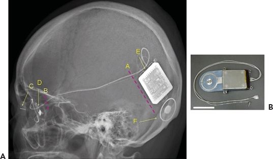
Figure 26.2 Diagram of retinal prosthesis system. A. Lateral view of the skull XP of Pt 1 after implantation surgery. A, Position of skin incision to insert and anchor the device. B, Position of skin incision to fix the cable to the bone of the lateral orbital wall. C, Return electrode. D, Stimulating electrode. E, Decoder. F, Secondary coil. B. The implanted devices, cable, and electrodes. Scale bar, 3 cm. (Reprinted with permission from Fujikado T, Kamei M, Sakaguchi H. Testing of semichronically implanted retinal prosthesis by suprachoroidal-transretinal stimulation in patients with retinitis pigmentosa. Invest Ophthalmol Vis Sci. 2011;52(7):4726. Copyright 2011. The Association for Research in Vision and Ophthalmology, Inc.)


FIGURE 26.3 Photograph of 49-channel stimulating electrode (A–D) and return electrode (A,B,E,F). Top (A) and side (B) views of stimulating and return electrode protected by protective silicone cover. Top (C) and side (D) views of 49-channel stimulating electrode. The diameter of each electrode is 0.5 mm, and the center-to-center electrode distance is 0.7 mm. The inset in (D) shows the protective cover that reinforced the junction between the electrode array and the cable. Top (E) and side (F) views of return electrode. The diameter of return electrode is 0.5 mm. Scale bars in (A–F), 5 mm. (Reprinted with permission from, Fujikado T, Kamei M, Sakaguchi H. Testing of semichronically implanted retinal prosthesis by suprachoroidal-transretinal stimulation in patients with retinitis pigmentosa. Invest Ophthalmol Vis Sci. 2011;52(7):4726. Copyright 2011. The Association for Research in Vision and Ophthalmology, Inc.)
Functional testing using head scanning revealed that the detection and discrimination of objects was possible with a small number of active electrodes. The resolution of the image with STS prosthesis may be lower because the electrodes are farther from the retina than they would be when utilizing either the subretinal or epiretinal approach. In addition, there is a potential need for greater stimulation thresholds, and a demand for increased power given the added distance. It is considered safer, however, as the electrodes do not touch the retina and are stably fixed in the sclera pocket.
SUBRETINAL IMPLANTS
In 1956, a retinal prosthesis was described in which a light-sensitive selenium cell was placed behind the retina of a blind patient, allowing the patient to discern a moment of light perception (23). Subsequently, microchips containing light-sensitive MPDAs were implanted between the neural retina and the retinal pigment epithelium. Access to the subretinal space is gained through internal or external mechanisms. It is achieved externally by a process in which the sclera is dissected down to the choroid, the choroid is excised, and the implant is placed in the desired location under the retina. Internal access is accomplished by a vitrectomy and retinotomy (24). A combination of the two methods may also be employed: fluid is used to detach the retina internally, and a choroidal incision is made externally. MPDAs are used to replace degenerated photoreceptors by rendering the transmitted light into small currents proportional to the light stimulus. Essentially, there is direct replacement of lost photoreceptor function.
In the case of hereditary retinal degenerations, the remaining intact neural tissue may be used to transmit and process image information. Subretinal implants require less current for stimulation because they are placed anatomically closer to the surviving bipolar cells, and they do not need adhesives or mechanical fixation. Inserting the microchip under transparent retina allows the microchip to sense light while simultaneously generating a signal through use of an array. Additionally, there is no need for either external cameras or processing units. It was considered that subretinal implantation may affect neurotrophic factors and enable a level of neuroprotection to the remaining viable tissue. Electroretinograms were assessed, which led to later suggestions that subretinal stimulation may preserve photoreceptors (25).
A consortium of universities in Germany developed and tested subretinally implanted MPDAs and used the device to transform visual scenes into electrical stimuli (26). Experimenting with in vitro and animal studies, they created a compatible and biostable implant. In addition, they employed a transchoroidal surgical technique for feasibility of implantation. Functionally, their subretinal implant moved in conjunction with the eye. There are two aspects to the implant: the MPDA with 1,500 elements that senses light using a photodiode, amplifies the signal, and connects the signal to the respective microelectrode (Fig. 26.4) and the additional electrode array of 16 electrodes for light-independent direct stimulation (Fig. 26.5).

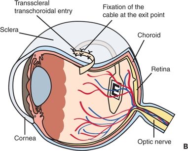


Figure 26.4 Implant position in the body A. The cable from the implanted chip in the eye leads under the temporal muscle to the exit behind the ear and connects with a wirelessly operated control unit. B. Position of the implant under the transplanted retina. C. MPDA photodiodes, amplifiers, and electrodes in relation to retinal neurons and pigment epithelium. D. Patient with wireless control unit attached to a neckband. E. Photograph of the subretinal tip at the posterior eye pole through a patient pupil. (A, B, C modified from; D, E. Reprinted from, Zrenner E, Bartz-Schmidt KU, Benav H, et al. Subretinal electronic chips allow blind patients to read letters and combine them to words. Proc Biol Sci. 2011;278:1489–1497.)


Figure 26.5 Implanted device and DS electrode arrays. A. Prototype of the implant with the MPDA on the polyimide substrate containing gold leads as conductive paths for the DS array and the MPDA. The 16 TiN electrodes of the DS array are visible at the inferior part of the implant. B. Layout of first-generation DS array. Electrodes are rectangular with dimensions of 50 × 50 μm with a grid spacing of 280 μm. C. Layout of second-generation DS array. Four TiN elements are grouped to form a single electrode. Those elements are separated by 20 μm from each other creating a compound electrode that covers an area of 120 × 120 μm. D. Fundus photo of participant 10 showing the chip implanted subretinally. Note the retinal vessels passing over the chip. (Reprinted with permission from, Wilke R, Gabel VP, Sachs H. Spatial resolution and perception of patterns mediated by a subretinal 16-electrode array in patients blinded by hereditary retinal dystrophies. Invest Ophthalmol Vis Sci.2011;52(8):5995–6003. Published on June 21, 2011 as Manuscript iovs.10-6946.)
A pilot study was undertaken in order to provide evidence that subretinally planted multielectrode arrays may restore visual function in patients affected by a retinal dystrophy. This study concluded that visual perception may be restored enough to provide patients with a degree of localization and recognition of objects; moreover, the potential to acquire enough vision to affect daily living (27). Further work is being performed to increase the level of spatial resolution.
In 2004, Chow et al. (28) reported on a pilot study in which an artificial silicon retina microchip was implanted in the subretinal space. The chip was composed of approximately 5,000 independent functioning electrodes and was powered entirely by incoming light. Their microchip was well tolerated; successful implantation was seen in six patients over 1 to 1.5 years with some degree of visual function improvement. As with other subretinal devices, visual improvement may result from the neuroprotective effect of the subretinal implant on photoreceptors (28). Rizzo and Wyatt produced a subretinal stimulator chip that receives information from a camera mounted on a pair of glasses. The subretinal implant decodes the information from the camera and stimulates ganglion cells accordingly.
There are certain limitations to the subretinal prosthesis, which include a more complex implant procedure and the potential for subretinal damage from thermal energy. There have been reports of histologic changes to the surrounding retina such as a decrease in the cellular density of the inner retina and a presence of macrophages at the implantation site (29,30). Additionally, an external power source is needed to achieve adequate power levels for signal amplification (31,32). Subretinal implants are subject to corrosion over time, which may change the surface characteristic of the implant and disintegrate the electrode (24). Furthermore, there is currently no method available to noninvasively determine the viability of the remaining retinal cells needed for the implant to work successfully (33). Damage to the remaining cells could mean that the transmitted information is nonspecific. For this reason, direct stimulation of the ganglion cells by an epiretinal implant may be preferred.
EPIRETINAL IMPLANTS
The epiretinal prosthesis is composed of extraocular and intraocular components. In contrast to subretinal electrodes, which rely on information transmitted posteriorly through the cornea and lens, the epiretinal implant requires a supplementary optical system. Moreover, there is no light-sensitive element, so additional processing is necessary to prepare the visual information. The optical system consists of a camera built into a pair of glasses, a battery source, and a small processing unit. The camera captures and digitizes information from the environment. The images are then transmitted electronically to the remaining surviving inner retinal neurons. These images are preprocessed and modified in such a way that they are easily transmitted from the retinal implant to the optic nerve and subsequently to the brain. Essentially, information is transmitted from an external device to an internal receiver and microelectrode array (34).
One of the greatest difficulties the epiretinal implant faces is the affixation of the structure to the retinal surface. A functional, chronic prosthesis was implanted for the first time by Humayun (35). A blind test subject was able to see phosphenes upon stimulating an electrode array. The patient could detect light, discern motion, and recognize simple shapes. In late 2011, interim results from Second Sight’s visual prosthesis were published, in which the Argus II retinal prosthesis system was evaluated. An electronic stimulator and antenna was sutured onto the sclera using an encircling silicon band. Following pars plana vitrectomy, electrode array and cable were introduced into the eye and tacked to the epiretinal surface. The camera first captured video before sending it to the processor, where it was converted to an electronic signal sent to the transmitter coil in the glasses. The antenna and receiver coil wirelessly received the data and sent the information to the electrode array where electrical stimulation pulses were emitted. The microelectrode induced cellular responses in the retina that traveled to the optic nerve and brain producing visual precepts. There was a 10% incidence of presumed endophthalmitis, which was treated medically, and two retina detachments, one of which may have been due to blunt trauma. The most common reported adverse event was conjunctival dehiscence over the extraocular implant. Subjects in the study had better ability in terms of object localization and motion discrimination. The best recorded visual acuity obtained in Second Sight’s visual prosthesis study was 20/1,260 (36). The Argus II retinal prosthesis was approved for sale in Europe.
Epiretinal implants may also nonspecifically stimulate the bipolar cells and ganglion cells of the inner retinal layer (37). Learning retinal implants, which are employed by Intelligent Medical Implants (IMI), use an epiretinal stimulator that is fixed onto the retina by a sclera tack. Using a wireless control, information is received through a camera mounted on eyeglasses. The information is modulated through an encoder; the settings on the encoder are calibrated in an iterative process until visual perception matches picture information (38,39).
A completely intraocular retinal prosthesis (Fig. 26.6) is under investigation by the Epiret 3 study group. The system is comprised of a computer system, a transmitter, and a transmitter coil. The receiver is implanted similarly to that of an intraocular lens within the sulcus but with a wired connection to the epiretinal array that is anchored to the retina with retinal tacks (40).

Figure 26.6 Concept of the EPIRET3 system. A transmitter coil sends data and energy to the receiver unit of the implant, which is located in the posterior chamber of the eye. The receiver unit is connected with the stimulator unit carrying an array of 25 3D IrOx electrodes by a flexible microcable. The stimulator is placed safely onto the retinal surface and fixed with retinal tacks. (Reprinted with permission from, Roessler G, Laube T, Brockmann C. Implantation and explanation of a wireless epiretinal retina implant device: observations during the EPIRET3 prospective clinical trial. Invest Ophthalmol Vis Sci. 2009;50(6):3003–3008. Copyright Association for Research in Vision and Ophthalmology.)
Stay updated, free articles. Join our Telegram channel

Full access? Get Clinical Tree


