58
Artificial Vision
Nancy Kunjukunju  Hirokazu Sakaguchi
  Motohiro Kamei
  Hugo Quiroz-Mercado
At one time, it was believed that visual loss was permanent once the neural retina or optic nerve had been damaged. There were two events that modified this way of thinking. In 1968, a visual prosthesis was evaluated in a blind patient (1), and in 1974 an experiment was conducted in which a patient with no light perception vision could perceive light after an electrode was used to stimulate the visual cortex (2). At present there are a number of groups working on different approaches to developing a visual prosthesis for the blind.
Dobelle developed an approach that stimulated the visual cortex intracranially (2–5). In experiments conducted by Dobelle et al. and Norman et al., using either implanted surface electrodes or intracortical microelectrodes, cortical cells were activated thus stimulating the visual cortex (2–5). This type of electrical stimulation of the visual cortex requires intracranial surgery and as such, there is the potential for a high rate of complications such as CNS infection, epilepsy, and disturbance of the blood flow to the optic nerve.
On the other hand, Santos reported that 30% of the ganglion cells and approximately 80% of the inner nuclear layer cells remain histologically intact after death of photoreceptors in the eyes with severe visual loss due to retinitis pigmentosa (RP) (6). Other groups, therefore, have approached the development of a visual prosthesis stimulating those remaining inner retinal neurons. One such ophthalmological approach involves the use of subretinal electrodes and has been investigated by Chow et al. (7–9) and Zrenner et al. (10, 11) (Figs. 58-1 and Figs. 58-2). Using this method, lost photoreceptor function is replaced by a subretinal microphotodiode array (MPDA) that activates the remaining retinal network. Another approach used by certain groups such as Eckmiller et al. (12, 13), Humayan et al. (14, 15), Rizzo et al. (16, 17) and Walter et al. (18) investigates the use of an epiretinal device to stimulate ganglion cells from an implanted microelectrode array from the vitreal side of the retina
(Fig. 58-3). Another viable option is approaching the retinal prosthesis from within the suprachoroidal space. Sakaguchi and Tano et al. reported regarding the suprachoroidal transretinal stimulation system (STS) in which an electrode upon insertion into the suprachoroidal space elicits an electrical evoked potential (EEP) through transretinal stimulation (19), and Fujikado and Tano et al. also reported the effect of this system in clinical trial (20).
There are advantages and disadvantages to each method of electrical stimulation. Implanted cortical electrodes can treat blindness with complete atrophy of the retina or optic nerve, but requires intracranial procedures and may result in limited spatial perception. Retinal stimulation (Fig. 58-4), in contrast, utilizes the preexisting signal-processing network along the proximal visual pathways and is expected to have higher resolution. The visual field through an epiretinal electrode for instance, has a visual angle of 10 degrees (21). However, the area of visual field that will be reconstructed by a small (several millimeter square or in diameter) electrodes array is limited. Retinal stimulation involves predictable retinal damage due to the chronic direct attachment of an implant array. Moreover, the epiretinal or subretinal electrode necessitates that sufficient bipolar cells or ganglion cells remain in the small area around the electrode to elicit a response to electrical stimulation.
At present, there are five clinical trials underway to evaluate the efficacy of visual restoration through retinal prosthesis (22). Second Sight Medical Products, Inc has a 16-electrode epiretinal device that has been implanted in six subjects in the United States for over five years (23). A second-generation device has 60 electrodes and is currently in phase 2/3 of a clinical trial. In Germany, Intelligent Medical Implants GmBH has implanted four patients with a 49-electrode epiretinal array (24). The fourth clinical trial involves another epiretinal implant, the EPI RET3, which is a 25-electrode array that was implanted for four weeks in six blind patients (25). In the fifth clinical trial a 1550-MPDA and a 4 × 4 electrode array from Retina Implant AG, Reutlingen, Germany, was implanted in the subretinal space of eight patients (26).
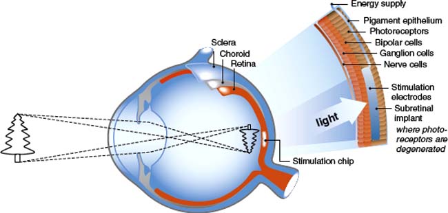
Figure 58-1. Subretinal implant (schematic).
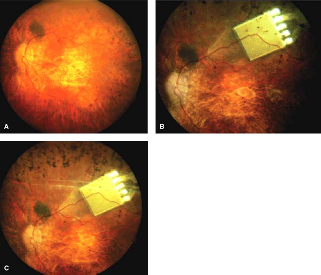
Figure 58-2. Subretinal implant (image as implanted under retina).
EPIRETINAL PROSTHESIS
In animal models, epiretinal stimulation was shown to reproducibly elicit neural responses in the retina. In humans, preliminary tests of epiretinal electronic stimulation showed that patients were able to identify a crude shape and there was no persistence of the image, either a letter or box shape, pursuant to stimulation (14, 15, 27).
The epiretinal prosthesis (Fig. 58-3) is composed of extraocular and intraocular components. The external component consists of a lightweight camera built into spectacles, pocket batteries and a small pager-sized processing unit. The camera is used to capture and digitize images from the external environment. These images are then transformed into patterns of electrical stimulation that can excite inner retinal neurons. Information and power are relayed from the external portion to an internal receiver/stimulating microelectronic chip and microelectrode array (28).
There are advantages and disadvantages to the epiretinal approach. The advantages include (a) the vitreous acts as a sink for heat-dissipation from the microelectronic device, (b) the implantable portion of the device has little microelectronics, (c) the wearable or extraocular portion of the device allows easy upgrades without needing subsequent surgery and (d) electronics allow user and doctor full control over every electrode parameter and digital signal processing involved in imaging objects. Disadvantages include (a) the techniques that necessitate prolonged adhesion of the device to the inner retina using retinal tacks, (b) a wire connecting extraocular and intraocular components forms a permanent track between the vitreous cavity to the outside, which may raise a possibility of late infection and detachment of the electrodes from the retina associated with the eye movement, and (c) the large amount of current required to stimulate target bipolar cells using an epiretinal device and be the close proximity of this current to target cells (28).
The Intraocular Retinal Prosthesis (IRP) developed in conjunction with Second Sight Medical Products, Inc. converts external images that are captured via camera into a pixilated image (15). The processed information is transmitted into the eye by magnetic coils in the form of controlled electrical pulses. A transscleral cable delivers the electrical stimulation pattern to an internal array of 16 platinum microelectrodes, ranging from 250 to 500 μm. The pulsed information transmitted to the microelectrodes on the array stimulates viable inner retinal neurons. Temporal to the fovea, the array is attached to the inner retinal surface via a tack that is inserted into the sclera (29). Canine retina implanted with the epiretinal prosthesis showed no evidence of rejection and examination of the retinal tack showed minimal effect on the retina (30).
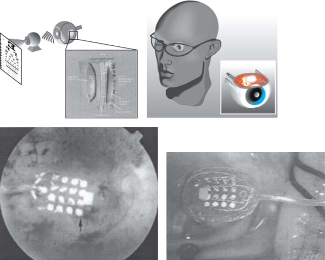
Figure 58-3. Epiretinal implant (schematic and implanted view).
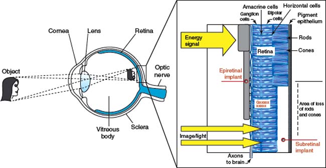
Figure 58-4. Subretinal and epiretinal implant (schematic).
Patients implanted with the epiretinal device were able to discriminate between visual precepts created by different electrodes based on position; they also had the ability to distinguish levels of brightness based on various levels of current (31). Patients perceived phosphenes in response to electrical stimulation and were able to detect motion as well as shapes. The external imaging system, for instance, was used by the patient to detect ambient light, locate a flashlight carried by a person 120 cm away and locate a dark object under normal room conditions. Additional tests seem to demonstrate that epiretinal stimulation can be conducted in a retinotopic manner. A higher pulse width signal for instance, stimulates retinal ganglion cells, while photoreceptors and bipolar cells respond to lower pulse width. Further, retinal ganglion cells respond to shorter pulse durations while deeper retinal layers respond to longer pulse durations. Testing appears to indicate that visual perception can be created with a maintained degree of retinotopy (32).
A second-generation version of the epiretinal device from Second Sight has 60 electrodes. The image processor will continue to be extraocular and information will be converted to a form of electrical stimulation that will excite inner retinal neurons. However, information will be transmitted wirelessly.
Rizzo and Wyatt at Harvard Medical School developed a second epiretinal prosthesis. The extraocular portion of the unit had an external battery pack, a charge coupled device camera (CCD) and a signal processing unit as well as a laser mounted onto a pair of glasses. The intraocular portion of their device was a photodiode panel and stimulator chip affixed onto a modified intraocular lens. A 10 μm thick polyimide electrode array was implanted onto the retina and attached to the retinal surface using a small gold weight and viscoelastic. The photodiode panel captured the processed signal from a laser pulse emitted from the glasses. This information was then delivered to the microelectrode array on the retinal surface of the eye by the stimulator chip. The device was implanted in five blind patients and there was no histological evidence of retinal damage from the electrical stimulation. Results from short-term studies were inconclusive and Rizzo and Wyatt abandoned the epiretinal implant for a subretinal implant (33).
A third epiretinal implant was developed by a consortium in Germany directed by Rolf Eckmiller. As is typical, this epiretinal implants has both intraocular and extraocular components. A retinal encoder (RE), which approximates the typical receptive field properties of retinal ganglion cells, replaces the visual processing capabilities of the retina by means of 100 to 1000 individually tunable spatiotemporal filters. The RE is situated in the frame of a pair of glasses. The RE processes visual
information and simulates filtering operations performed by individual ganglion cells. The RE output is encoded and transmitted via a wireless signal to the implanted retinal stimulator (RS). The RS is a microcontact foil centered on the fovea and fixed to the retinal surface. The RS must be in contact with a number of retinal ganglion cells to elicit electrical spikes. Visual patterns are mapped onto spikes for the contacted ganglion cells through the RS. The REs simulate a complex mapping operation of parts of the neural retina, but also provide a perception-based dialogue between the RE and human subject. This dialogue tunes the various receptive field filters with information “expected” by the central visual system to generate optimal ganglion cell codes for epiretinal stimulation (12).
SUBRETINAL PROSTHESIS
In the subretinal (Figs. 58-1 and Figs. 58-2) approach to visual restoration, a MPDA is implanted between the neural retina and the retinal pigment epithelium. In animal models, subretinal stimulation has been shown to elicit neuronal activity in retinal ganglion cells. Access is gained to the subretinal space by one of two methods: ab externo (through the scleral and choroid) or ab interno (through the vitreous cavity and retina).
One advantage over the epiretinal approach is that the microphotodiodes of a subretinal prosthesis replace the functions of the damaged photoreceptor cells because the remaining intact neural network in the retina is still capable of processing electrical signals. The subretinal implant is anatomically closer to the next surviving neuron in the visual pathway (bipolar cells) and thus should require less current for stimulation. Subretinal placement eliminates the need to have adhesives to hold the implant in place; as no mechanical fixation is required, there is less surgically induced trauma upon implantation. External cameras and processing units are not necessary and the patient’s eye movements can be used to locate objects. Additionally, initial prototypes of the model apparently do not require external power sources and may use solar cells (10, 11, 34–38). It has also been postulated that the electrical stimulation provided by the subretinal implant may affect neurotrophic factors that provide neuroprotection to the retina. In certain studies involving subretinal implantation in rat models, in which electroretinogram (ERG) responses were assessed, there was some suggestion that subretinal electrical stimulation may temporarily preserve photoreceptors (39). The stimulation of various neurotrophic factors may also be due to the mechanical presence of the implant in the subretinal space (40).
A consortium of research universities in Germany under the guidance of Eberhart Zrenner has an implant that consists of a MPDA, which contains 7000 microelectrodes in a checkerboard pattern configuration. The device is 3 mm in diameter and 50 microns in thickness. Each MPDA has an area of 400 μm2, is made of biocompatible silicon and silicon oxide, and is designed to be both insulating and permeable to light. Prototypes of their subretinal device have an external power source that supplies energy to the subretinal implant by means of very fine wires that are run outside of the eye (10, 11, 15, 34–38).
There are certain limitations to a subretinal prosthesis. Current photodiode technology is inefficient. The current power retained from solar cells does not provide enough energy to generate enough electricity to power the needed levels of illumination. This lack of an energy source may mean that the subretinal prosthesis will require active power supplementation from an external source in order to achieve adequate power levels (34, 41, 42). Although an extracorporeal connection does not qualify for permanent use in patients, seven volunteer patients with RP were implanted with a subretinal implant connected to an extracorporeal connector in the retroauricular space via a transscleral, transchoroidal cable. Energy was supplied by gold wires on a transscleral, transchoroidally implanted polymide foil leading to the lateral orbital rim where it was fixated and connected to a silicone cable. To overcome this transcutaneous cable connection the receiver of a wireless system may be placed either subcutaneously in the retroauricular space, episclerally, or even intraocularly via a modified intraocular lens in the capsular bag (43). Other research is being conducted to increase the spectrum of photodiode absorption to include infrared light to increase energy delivery to the potential array (35, 41, 44). Finally, the subretinal area is limited and heat dissipation may cause thermal injury. There are reports of histological changes to the surrounding retina that includes a decrease in the cellular density of the inner retina, expression of glial fibrillary acidic protein (GFAP) in the Muller glia, and the presence of macrophages at the implant site (34, 41, 45). In animal models, the photoreceptors facing the subretinal implants underwent degenerative changes associated with underlying glial tissue. Studies are currently targeting the shape and coating of the subretinal prosthesis to enable better integration with the retina. The effects of various coatings such as silicon oxide, iridium oxide and parylene and three geometries—flat, pillars, and chambers—are being studied (46). The next generation of prostheses may include porous architecture, allowing nutritional exchange between the retina and the underlying choroids in order to alleviate any histological changes (35).
OPTIC NERVE ELECTRODES
A Belgium research group implanted a spiral cuff electrode that supported four electrodes around the optic nerve of a blind patient with RP (47, 48). The patient perceived corresponding phosphenes in different locations whenever the pulse width, current intensity, the number or frequency of the stimulus train was changed. Using this system a volunteer with RP could recognize “U” and “L” shape patterns after training (47). Although animal studies have shown that it is possible to stimulate the optic nerve and elicit visual evoked potentials (49, 50), the optic nerve is a tightly packed bundle of axons of ganglion cells, and direct stimulation of a small area of the optic nerve would be expected to activate a large segment of the visual field. Consequently, spatial resolution is potentially limited because optic nerve stimulation with a relatively large contact area of a cuff electrode may hinder detailed perception. However, selective and localized axonal stimulation by a multiple microelectrode array with low charge density may yield higher visual resolution.
A Japanese research group developed a method of electrical stimulation of the optic nerve with a set of transvitreous, needle-type electrodes as a viable, novel approach to a visual prosthesis. Sakaguchi et al. determined that transvitreous electrical stimulation of the optic nerve would elicit EEP in albino rabbits (51). The electrical stimulation of the optic nerve activates the primary visual pathway. This approach to optic nerve stimulation has the advantage of leaving the brain intact as it requires no intracranial surgery. Moreover, it was reasonable to assume that more selective and localized microstimulation of axons by an intrapapillary microelectrode with a low charge density would activate functionally distinct subunits within the optic nerve and provide blind patients with better spatial resolution.
The methodology involving the implantation of optic nerve electrodes involves platinum wire coated with epoxy resin. Platinum is proven biocompatible electrode material that is used in long-term neural stimulating electrodes because of the superior charge transfer properties (52). The technique used for optic nerve electrode implantation mimics a similar technique using radial optic neurotomies for vein occlusions (53). Visual field defects related to the neurotomy site have been noted in vein occlusion surgery, which indicates that there is damage to either the optic nerve fibers or the blood supply following surgical manipulation (54). Nevertheless, it is hoped that these complications can be managed by the use of platinum wires that are thinner than the microvitreoretinal knife used in radial optic neurotomy surgery. Early histological examinations revealed no major complications, such as bleeding or degeneration when two needle-type electrodes were inserted into the optic nerve using a transvitreal approach. The preliminary study determined that electrical stimulation of the optic disc by 200 μm diameter needle-type electrodes could elicit electrically EEP. These electrodes were relatively large and instead 50 μm diameter electrodes were implanted to evoke cortical potentials. The wire electrodes were implanted and fixed into different portions of the optic disc without serious complications in 16 eyes. EEPs were elicited after biphasic stimulation of the optic nerve and histological evaluation revealed limited damage to the neural tissue adjacent to the electrode track. Such damage can result from mechanical injury caused by the electrode as well as from chronic neuronal tissue reaction to the electrode implantation. Electrical stimulation of the nerve is a concern as it was noted that electrical stimulation of the optic nerve head can affect circulation. Sugiyama et al. (55) observed that a current of 5 mA could decrease the blood supply of the optic nerve head. However, Morimoto et al. (56) showed that in vivo optical nerve stimulation with less than 70 micro (U) amps of current for 2 hours can enhance the survival of retinal ganglion cells.
After determining that it was feasible to implant transscleral wire electrodes into the optic nerve head, further work was done to conclude that transscleral intrapapillary wire electrodes were stable and tolerated for a longer duration of time (57). Four platinum electrodes were passed through the sclera and implanted into the optic nerve head of five rabbit eyes over the course of 4 to 6 months. The retina was monitored with color fundus, fluorescein angiography, ERG and visually evoked potentials. EEP were elicited by bipolar electrical stimulation of the optic nerve axons immediately after implantation and at one-month intervals. Except for one electrode that pulled out of the optic nerve head at 1 month after implantation, all electrodes remained stable in the implanted sites throughout the postimplantation period. There was no evidence of intraocular infection, inflammation, or vitreoretinal proliferation in any eye. Histological evaluation of the optic nerve revealed tissue encapsulation surrounding the electrode and increased expression of GFAP near the surface of the optic nerve. The visual cortex was activated by direct electrical stimulation of the optic nerve axons with the same charge at each monthly interval. Following this experiment, it was concluded that chronic implantation was a feasible option.
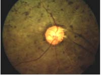
Although atrophy and degeneration of the nerve fibers combined with the hypertrophy of the glial cells and connective tissue structure within the optic nerve head of the RP patient may make implantation difficult, the implantation of the electrodes appears to be simple. A study was performed in which the efficacy and safety of direct optic nerve electrode induced artificial vision (AV-DONE, artificial vision by direct optic nerve electrodes) was studied in a blind patient with RP. The device was implanted into the optic disc of an RP patient with no light perception vision (Fig. 58-5). Phacoemulsification was performed prior to implantation. The device was comprised of three 0.05 mm wire electrodes. A silicone tube containing parylene coated platinum wires (each 0.05 mm) encircled the globe and was sutured at the four scleral quadrants with a 5–0 suture. A standard pars plana vitrectomy was performed with confirmed posterior vitreous detachment. The wire bundle was then inserted into the vitreous through the sclerotomy at 3.5 mm from the limbus. Three wire tips were inserted into the optic nerve using vitreoretinal forceps. The tips were inserted into the disc at a 1 to 2 mm depth away from the vessels. Another wire was left in the vitreous cavity as a reference electrode. The external wires were covered with tenon’s capsule and conjunctival tissue. At the time of electrical stimulation, a peritomy was performed and the wires were connected to the outside stimulator. The wires were functionally stable for 12 months. Phosphenes, visual sensations, were elicited by electrical stimulation through each electrode. The threshold for phosphene perception was elicited by pulses of 0.25 ms duration/phase and a pulse frequency of 320 Hz. The phosphenes ranged in size from a match head to an apple, were round oval or linear, primarily yellow and focally distributed. There were no complications during the follow-up period. The trial was limited by the absence of a transcutaneous transmission system to draw a complete and accurate phosphene map; nonetheless, it was successful in showing that localized phosphene perceptions were elicited by stimulating the optic nerve in a patient with advanced RP (58). The wire electrodes were implanted and fixed into different portions of the optic disc without serious complications in 16 eyes
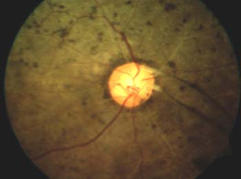
Figure 58-5. The insertion of the platinum wire electrodes into the optic disc. Three wire electrodes were inserted into the optic disc of the right eye, which had no light perception with retinitis pigmentosa. The electrodes were stable until at least 12 months.
Stay updated, free articles. Join our Telegram channel

Full access? Get Clinical Tree


