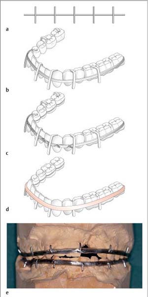
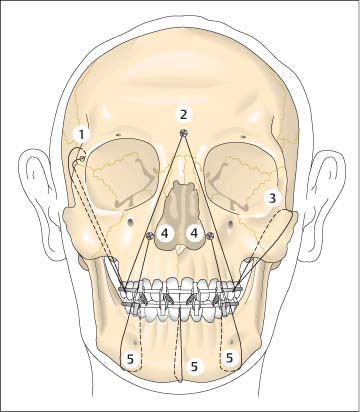
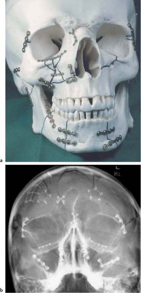
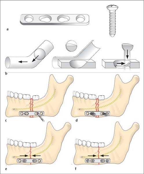
19 Treatment of Injuries of the Midface Splinting serves different purposes in dental luxation and jaw fractures. Splinting in tooth luxation injuries provides stabilization and immobilization following repositioning of the teeth. In conservative management of midface or mandibular fractures, various splinting techniques are utilized to stabilize the upper and lower jaws in normal occlusion, generally using splintage secured to the teeth. Splints are also often a necessary component in osteosynthesis techniques. Under favorable conditions, they can be removed immediately after placement of osteosynthetic devices. Splints must often remain in place for several weeks to support wound healing, achieve fine corrections, or for a combined conservative and surgical approach. This is particularly true for treating condylar process fractures. Splinting can be used as the sole treatment procedure in particular for tooth luxation, alveolar process fractures, nondisplaced fractures of the mandibular ramus including the temporomandibular joints, as well is in the pediatric jaw. Conservative management with splinting is also often used for nondisplaced fractures of the mandibular body and displaced joint fractures. Splints can be divided into the following types: The simplest intraoral splint is the wire ligature. It can be placed quickly and requires little material. Soft steel wire with a diameter of 0.4 or 0.5 mm is used. The ligature based on Ernst is a figure-eight ligature placed around two adjacent teeth, preferably including the premolars and first molar. Certain intermaxillary immobilization is established by placing at least one ligature in each quadrant and then connecting the ligatures to each other with elastic bands or wire (Fig. 19.1a). A number of modifications and developments in wire ligatures have been described. Wire ligatures can also be reinforced with acrylic. Such splints are mostly useful for temporary immobilization of the jaw until definitive fracture treatment (Fig. 19.1b,c). Trauma to the gingiva caused by fabricated wire splints is not inconsiderable. In addition, they can cause undesirable orthodontic movement of individual teeth. Thus, their use has largely been abandoned in favor of metal arch bar/acrylic splints (Schuchardt splint). This splint is made up of a prefabricated, soft, 2-mm thick semicircular arch bar with 1.4-mm thick transverse wire projections. After reducing the fracture, the wire splint is contoured as exactly as possible to the equator of the vestibular surfaces of the teeth. At the same time the occlusal sides of the projections are bent over the occlusal surfaces of the teeth, so that when tightening the wire ligatures the splint is prevented from slipping and coming into contact with the gingiva. After adaptation of the ligatures, the metal arch bar and ligature ends are reinforced with self-curing acrylic. Care should be taken not to crush the marginal periodontium or interdental papillae. After the acrylic has hardened, the occlusal surface wires are removed and the surface of the splint smoothed and polished (Fig. 19.2a–d). In fractures of the maxilla and alveolar process, or in sagittal fractures, the splint can be made more rigid with an acrylic palatal plate. For edentulous portions of the jaw, splints can be furnished with an acrylic saddle. Fig. 19.1 Intraoral splints (from Schwenzer and Ehrenfeld, Vol. 2, 2002). a Simple wire ligature (1) and figure-eight ligature based on Ernst (2) for temporary mandibulomaxillary fixation. b Continuous loop wiring based on Stout. c Wire splint based on Sauer. Indirect metal arch bar/acrylic splints (Muenster dental model) are fabricated after taking impressions of the jaw. If there are fractures within the dental arch, so-called model surgery must be performed. The advantage of this type of splint is its quick and simple application, sparing the patient discomfort. The splint lies directly on the dental arch, avoids injury to the marginal periodontium, and is easily removed. The disadvantages of this type of splint include the necessity of laboratory fabrication, which delays management and involves increased costs (Fig. 19.2e). Cap splints, commonly made of acrylic, and rarely of metal, cover the teeth completely: Denture splints are used for edentulous jaws. If the patient wears dentures and these were not destroyed in the accident, they can be used for immobilization. The dentures are securely fixed using circumferential wiring (see Fig. 19.3) of the mandible or by suspension wiring firmly fixed to the maxilla and then connected to each other with wire ligatures. The activator is an orthodontic appliance. A modified form of the device is also used for primary management or functional treatment of temporomandibular joint fractures. The device produces extension in the temporomandibular joint, thus preventing shortening in the fracture region. The head/chin strap is one of the oldest types of bandages used in the management of jaw fractures. It is used only for temporary immobilization in exceptional situations, however, as it offers insufficient stability and can obstruct breathing if it slips. Emergency immobilization is achieved using the wooden spatula bandage (see Fig. 1.6, p. 7). The chin cap bandage is an important element in extraoral bandaging. All fixation devices (Stenzel frame, chin cap) are attached to it. A far more stable device is the halo frame, a metal crown that is fixed to the calotte with screws. Holes for fixation are located in the arc of the frame, allowing various rods and clamps to be placed in any position desired and connected with intraoral splints. Fig. 19.2 Metal arch bar/acrylic splint based on Schuchardt (a–d from Schwenzer and Ehrenfeld, Vol. 2, 2002). a Prefabricated soft metal arch bar with transverse wire projections. b Contoured metal arch bar. The transverse wires on the occlusal surface prevent the splint from slipping. c The wire splint is secured to the teeth with individual ligatures. d Finished splint. The occlusal surface wires are removed after reinforcing the splint with acrylic. e Metal arch bar/acrylic splint (Muenster dental cast) on the model following model surgery. External fixation techniques derived from surgery of the extremities occasionally are used for stabilizing mandibular fractures in edentulous patients. Percutaneously inserted screws are connected using special screw clamps and rods or even acrylic. In rare instances, reduction and stabilization measures may be unnecessary in nondisplaced fractures of the midface, without associated dislocation, malocclusion, or abnormal mobility. Close observation is mandatory to ensure that potential dislocations are identified in time. A liquid or soft diet is prescribed for about 6 weeks, until there has been sufficient osseous consolidation of the fracture sites. This procedure is predominantly used for edentulous patients. Splinting of the maxilla can be considered as a sole treatment measure in alveolar process fractures if the larger portion of the alveolar process is not fractured and if both fragments have sufficient dentition. Splinting can be achieved using a wire/acrylic splint with a palatal plate. If dentures are available, these can be refashioned into a splint. The splint remains in place for 6 weeks. Intermaxillary fixation of maxilla and mandible is insufficient by itself for immobilization in midface fractures, as movement of the mandible in the temporomandibular joint is possible, thus allowing movement of the maxilla. Additional fixation of the maxilla to the cranium is necessary. In rare situations stabilization can be achieved with splinting of the upper and lower jaws, along with inter-maxillary wiring, and cranial stabilization with a halo frame and Stenzel appliance. A slightly modified form of this procedure is experiencing a renaissance in the field of callus distraction in the treatment of severe malposition of healed midfacial fractures and in surgery of craniofacial deformity. Craniofacial suspension wiring, based on Adams (Fig. 19.3), can be used in place of extraoral fixation devices that are an unavoidable part of conservative management. Suspension wiring (0.4–0.5-mm thick, soft steel wire), running through the soft tissues and attached to the frontal bone, pyriform aperture, zygomatic arches, or frontozygomatic suture, fixes the maxilla splint to the facial skeleton. Suspension wiring generally remains in place for 6 weeks; intermaxillary wiring is required for 3–6 weeks. Maxillomaxillary suspension wiring: Suspension wiring runs from the margin of the pyriform aperture to the maxillary splint. Maxillomaxillary wiring can be used as a complementary procedure to suspension wiring of the zygomatic arches in Le Fort I fractures. Zygomatic arch suspension wiring: Here the suspension wiring consists of a wire looped around the zygomatic arches. This procedure can be used for all fracture sites inferior to the zygomatic arch and in which the stability of the zygomatic arches is not compromised (Le Fort I infrazygomatic fractures, alveolar process fractures, pyramidal fractures). Fig. 19.3 Craniofacial (internal) suspension wiring (from Schwenzer and Ehrenfeld, Vol. 2, 2002). 1 Frontomaxillary suspension; 2 frontal bone suspension based on Kufner; 3 zygomaticomaxillary suspension; 4 suspension on the pyriform aperture using osteosynthesis screws; 5 perimandibular wire looping (circumferential wiring). Medial frontal bone suspension: In this procedure based on Kufner, a screw is placed in the center of the forehead above the root of the nose. Suspension wires run from there along both sides of the bony nasal skeleton to the maxillary splint. Suspension wiring cranial to the frontozygomatic suture: This procedure is used for centrolateral type III Wassmund fractures and Le Fort III fractures, if the zygomatic arches cannot be used for fixation. Suspension wiring is as a general rule fixed at a point cranial to the frontozygomatic suture. Despite the often delicate structures of the midface, miniplates, microplates, and three-dimensional plates can be fixed to nearly any sufficiently stable site. Stable and anatomically exact three-dimensional reconstruction of the midface is thus possible, as is the maintenance of areas of bone vital to function such as the anterior wall of the maxillary sinus (Fig. 19.4). Plating has made it possible to reconstruct the original facial dimensions, i. e., anterior projection (profile), transverse dimensions (facial width), and vertical dimensions (facial height) in correct occlusion. At the same time the patient can be spared the considerably unpleasant weeks-long intermaxillary wiring. Stable fixation shortens the duration of injury course and allows early mobilization of the temporomandibular joint in combination injuries with involvement of the joint. The risk of infection is very low, even compared to wire osteosynthesis. The disadvantages include cost of implantation, implant removal—which is often necessary—and especially the often difficult surgical technique. Various miniplate, three-dimensional plate, microplate and three-dimensional microplate systems are available. Plate thicknesses range between 2.0 and 0.5 mm. Plates are fixed using self-tapping screws. Microplates are used for fixation of the thin, nonload-bearing skeletal portions of the anterior wall of the maxillary sinus, nasoethmoidal complex, infraorbital region, and forehead. Miniplates are used to stabilize the force-transmitting structures of the nasal and maxillojugular buttresses. Attention should be paid to first restoring the supporting buttresses of the midface that absorb masticatory forces and form the trajectory system (nasal, maxillojugular, and pterygopalatinal pillars). Plates should therefore be placed longitudinally to the pillars, parallel to the trajectory system. To ensure maximum stability, every hole in the plates should have a screw placed in it. Screws must be firmly tightened, as loose screws pose a risk of infection in much the same way as unstable osteo-synthesis does. Fig. 19.4 Position of miniplates and microplates for reconstructing a complex fracture of the midface. a Plates on a model of the skull. b Radiograph of a complex fracture of the facial skeleton. Further surgical measures, for example, reconstruction of the orbital floors, repositioning of the nose, and drainage of the paranasal sinuses, are taken only after reduction and stabilization of the midface. Osteosynthesis techniques result in functionally stable inter-fragmentary fixation with simultaneous retention. In other words, osteosynthesis offers an instrument that unifies fixation and retention systems. Wire fixation of midface fractures can effectively ensure adaptation of bony fragments, but it is insufficiently stable for use alone without additional procedures such as suspension wiring, splinting, and intermaxillary fixation. Wire osteosynthesis can be used for temporary fixation of bone fragments or in regions that are not acted on by compressive and tensile forces (anterior wall of the frontal sinus, anterior wall of the maxilla). The goal of stable osteosynthesis is total immobilization of fragments eliminating the need for additional fixation devices and, ideally, achieving primary fracture healing. The most common procedure for absolute immobilization is interfragmentary compression, which produces static friction between the fracture surfaces using axial compression, which prevents fracture fragments from further displacement. Interfragmentary compression systems include: Compression plate osteosynthesis: Interfragmentary axial compression is created by the special geometry of the holes in the compression plate, along with the eccentric placement of the screw. The screw head resembles a sphere that is inserted in an inclined plane, i. e., the plate hole. As the screw is tightened, the vertical downward movement of the screw head and screw is converted to horizontal movement of the plane (the plate moves away from the fracture gap) resulting in compression of the fracture ends. In order for this to work, the screw must be inserted eccentrically, with the drilled hole placed at a distance from the fracture. Specially designed drill bits and drill guides are available (Fig. 19.5). Fig. 19.5 Compression osteosynthesis (from Schwenzer and Ehrenfeld, Vol. 2, 2002). a Compression plate (dynamic compression plate, DCP) from the AO foundation. Four-hole DC plate with screw. b Spherical gliding principle of the dynamic compression plate. Upon tightening the screw, the screw head produces horizontal movement of the plate. c After reducing the fracture and adapting the osteosynthesis plate, the mandible is drilled through the small diameters of the eccentric inner plate holes. d Compression screws are inserted and tightened. e Upon tightening the screws, the spherical screw head is moved toward the larger circumference of the plate holes, causing the bone fragments to move toward each other. f Tightening both outer retention screws. Lag screw osteosynthesis: The lag screw principle is based on the following: As the screw is tightened the fragments are pressed against each other. To prevent the screw pulling through the gliding hole, an underlying plate can occasionally be placed. Figure 19.6 illustrates the principle underlying lag screw osteosynthesis. The most commonly used osteosynthesis technique applied in facial skeleton fractures is microplate or mini-plate placement to ensure bone adaptation. This management approach involves realignment and fixation of the fracture ends in their anatomically correct position. Tensile forces are absorbed by the plates, while compression forces are transmitted through the bones. Fig. 19.6 Lag screw osteosynthesis (from Schwenzer and Ehrenfeld, Vol. 2, 2002). a Preliminary drilling of the screw hole in the inner fragment. The drilled hole in the outer fragment has already been widened to serve as a gliding hole. b Cutting the thread in the inner fragment. c Screwing the lag screw into the threaded hole. d Compression of both fragments with tightening of the screw. Screws are the most important element in plate fixation and fragment stabilization (lag screw). Proper selection and placement of screws is the key to ensuring good stabilization of fractures or osteotomies. Even the best plate is useless if it is not fixed securely with the appropriate screws according to fracture type, localization, and bone mass. Screws are classified according to diameter and thread type. The screws that are mainly used in facial surgery have threads covering the entire screw. The thread is cut asymmetrically to the screw core, similar to a cortical screw. Screw diameter is between 1.0 and 2.7 mm (thread diameter). If the primary screw strips, so-called emergency screws are available for most screw sizes. These are slightly larger in diameter and can grip the bone (Fig. 19.7a,b). The screw is held in place by friction between the screw threads and the bone. Two different methods of creating a threaded hole are used: Self-tapping screws: Screws with self-tapping threads are based on the principle of wood screws. After drilling a hole in the bone with a diameter only slightly smaller than the screw diameter, the screw is inserted in the hole and tightened. There are two types of self-tapping screws: Thread-cutting screws combine the principle of a screw and a tap in one. Two or three flutes are located in the tip of the screw to clear bone debris produced by threading the hole as the screw is turned. Screws must be tightened in a “two-steps-forward-one-step-backward” fashion so that bone debris can be cleared by the appropriate flutes (Fig. 19.7c). The thread-forming screw, which presses the threads into the bone, does not have any flutes for clearing bone debris. Threaded holes: Inserting screws into threaded holes requires preliminary drilling of a hole and pretapping. Using a threaded hole requires screws possessing deeper threads. Their holding capacity is determined by an exact fit between the screw and the threaded hole and the large surface contact area created with the bone. This procedure allows screw removal and precise reinsertion at a later time. It finds use especially with compression osteosynthesis and temporary mandibular osteotomy. Fig. 19.7 Screw nomenclature. a Schematic illustration of a screw. b Various screw heads. c Difference between screw tip in thread-forming and thread-cutting screws. d Monocortical and bicortical screw fixation. Screw fixation can be monocortical or bicortical (Fig. 19.7d): The most crucial step in securing the plate is proper and exact screw placement. The stability of bony fixation is also dependent on the chosen plate dimensions, but the holding power of the screws in the bone is more important. Imperfect drilling of the screw holes or flawed insertion of the screw in the bone results in insufficient mechanical stabilization of the fracture. Drills: Every screw must be exactly matched to a suitable drill. If the drill canal is too wide, the screw will not have adequate gripping power. If the canal is too narrow, forceful insertion of the screw will strip the threads, likewise resulting in inadequate holding capacity. The length of the drill bit can vary. Drills come either with or without a depth stop that allows only brief drilling to a maximum depth. When drilling, care should be taken not to allow the drill to come into contact with metal objects—for example, plates—as the resulting cuttings interfere with wound healing. Drilling should always be preformed with cooling irrigation, sharp drill bits, and a maximum torque of 600/min (Fig. 19.8a). Drill sleeves allow the drilled hole to be lined up exactly with the plate hole. A distinction is made between concentric drill sleeves, which place the drilled hole exactly in the center of the plate hole, and eccentric drill sleeves, as necessary for positioning screws in compression plates. For compression plating, the plate hole must always end up distal to the fracture gap. Drill sleeves also protect surrounding tissue from trauma caused by the drill. A depth gauge (bicortical screws) is used to measure the length of the screw required for exact fixation. A sliding metal hook grasps the opposite side of the bone and, after the instrument has been advanced to the bone, the screw length is measured. If the exact screw length is not available, a slightly longer screw should always be selected. The stability of a screw in the bone is higher if the concentric screw tip protrudes from the bone. Screw length is measured before cutting the thread (Fig. 19.8b). Screwdrivers are available for every screw size and type of screw head. Screwdrivers are used for holding and inserting the screw. A firm and exact fit between the screwdriver and the screw head must be ensured to avoid damaging the screw head. The screwdriver handle corresponds to the screw dimensions to prevent excessive force transmission (Fig. 19.8c). Meticulous instrument handling in the proper order is essential for screw placement. 1. Drilling the screw hole: – Drill bit size must correspond exactly to screw diameter. – The drill must be cooled while drilling. – The rotational speed of the drill must not exceed 600/min. At greater speeds there is thermal damage to the bone, followed by bone necrosis and escape of the screw. – The drill canal must be drilled in one pass and exactly in the planned direction. Multiple attempts at redrilling or even changing direction eliminate the holding capacity of the screw in the widened drill canal. – A drill guide should be used for exact placement of the screw in the middle of the plate hole. Fig. 19.8 Instruments for placing screws and adapting plates. a Various drill bits, the top one without a depth stop and the bottom one with a depth stop. b Depth gauge for determining screw length. c Screwdrivers for various screw thicknesses. d Aderer pliers for plate bending. – The length of the screw should correspond to the bone thickness and take monocortical versus bicortical fixation into consideration. – The flutes in the tip of a self-tapping screw reduce the holding power of the screw in the bone, and thus the fluted portion should end up positioned outside of the bone. – However, the screw should not penetrate the tissues beyond the bone too deeply, as damage to anatomic structures such as nerves or vessels, or infection, for example, with mucosal contact in the paranasal sinuses, can result. 3. Pretapping: – Pretapping is only necessary for nonself-tapping screws. – Care should be taken that the tap is positioned at exactly the same angle as the drilled hole. – The thread is cut in a two-steps-forward-one-step-backward fashion to allow clearing of bone debris by the flutes in the tip of the tap. 4. Inserting the screw: – The screw can now be inserted into the bone. Insertion of self-tapping screws must also be done in a two-steps-forward-one-step-backward fashion to enable the screw to cut its own thread. – The screw should ultimately be firmly inserted in the bone, without being overtightened as this strips the thread (“after firm comes loose”). – If the turning moment exceeds the stability of the screw at the junction between the screw head and thread, the screw head can separate. Possible causes include: – The drilled hole is not sufficiently deep. – The screw is too long for the hole. – The selected diameter of the screw is too narrow for the bone, which is too compact. – The chosen screw material does not meet the required standards. The purpose of plate osteosynthesis is to ensure adaptation of the fractured bone in its exact anatomic position and to neutralize forces acting on the fracture fragments. Muscular pulling forces from muscles attached to the bone are the main source of force. If forces are inadequately neutralized, the fragments will loosen, become redisplaced with resulting gap formation, and in the worst case there will be formation of osteitis in the fracture gap or pseudarthrosis. Thus, assessing the forces acting on the fracture fragments is imperative. Bending instruments: The three-pronged bending pliers (Aderer pliers) have three intertwined prongs to bend plates without causing significant deformity of the holes. These can generally bend the plate at its connecting bridges along the edge and surface, i. e., in two opposing planes (Fig. 19.8d). Cutting instruments: Plates can be shortened using sharp pliers (side cutting nipper). Care must be taken to keep the cut edge as smooth as possible as it can otherwise interfere with wound healing. Plate-holding instruments: A whole range of instruments—such as forceps—can be used to hold the plate in position after it has been contoured to the bone. As the approaches to the fracture site are often narrow, most surgeons prefer using an anatomic forceps. Visualization of the full extent of the fracture is always a prerequisite for plate placement. This includes complete vision of the placement surfaces for the plate on all fracture ends. The plate always must be fixed with at least two screws on each fragment end, i. e., the stable portions of the fragments.
 Flowchart and Checklist Craniofacial Injuries, Chapter 3, p. 20.
 Antibiotic Therapy, Chapter 24, p. 210.
 Diagnosing Injuries of the Midface, Chapter 9, p. 69.
Conservative Management
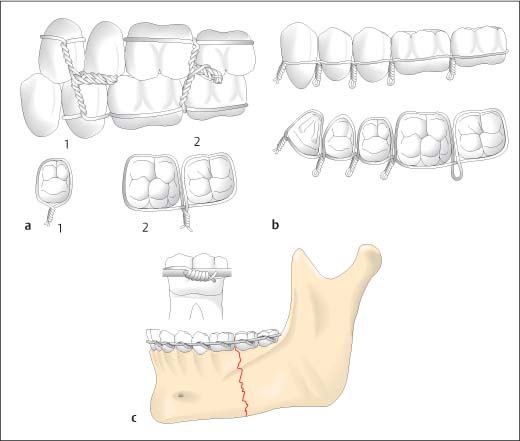
Splinting
 Extraoral splints: These splints externally surround and support the broken bone (chin cap, nasal bandaging).
 Intraoral splints: These splints are attached to the teeth (wire ligatures, arch wires, cap splints) or are placed on the edentulous jaw in a similar fashion to a prosthesis (denture splinting).
 Combined extraoral/intraoral splints: Extraoral splinting (head bandaging, halo appliance) is combined with intraoral splinting.
Intraoral Splinting
 The simplest form is the miniplast fabricated tray, which is a heat-formable tray splint fabricated after taking an impression of the jaw. The splint is secured to the teeth either by a clamp effect, cement, perimandibular wire looping (circumferential wiring) around the mandible, craniofacial wiring of the maxilla, or is fixed with osteosynthetic screws. Miniplast fixation is relatively unstable and is thus suitable only for splinting luxated teeth or management of limited alveolar process fractures.
 More stable cap splints must have a surface that is adjusted according to gnathologic aspects. Only then are exact occlusal restoration and undisturbed function possible during the consolidation phase. Such splints must thus be constructed with the assistance of an articulator. They are usually made of plastic and only rarely of metal. Occasionally, they are so stable that fixation against the maxilla may be unnecessary in non-displaced fracture of the dentate mandible.
Extraoral Splinting
Controlled Spontaneous Healing
Monomaxillary Fixation
Intermaxillary Fixation
Intermaxillary Fixation and Stabilization with a Halo Frame
Surgical Procedures
Craniofacial Suspension Wiring
Osteosynthesis with Miniplates and Microplates
Osteosynthesis Techniques
Wire Osteosynthesis
Compression Osteosynthesis
 Compression osteosynthesis with a dynamic compression plate;
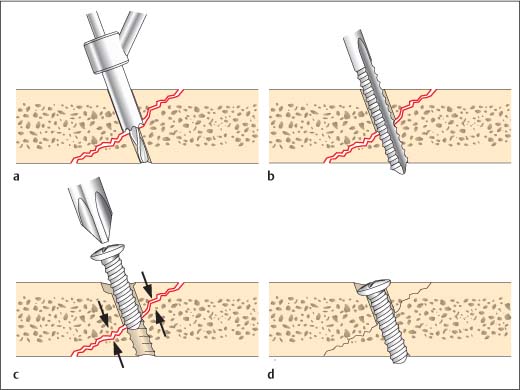
 Lag screws.
 Screws are placed directly in the fragments without utilizing plates;
 The screw thread only engages the fragment on the far side of the fracture gap. In addition, the screw hole is threaded only in the fragment furthest from the screw head (countersink hole); the wider drill canal (the gliding hole) in the fragment nearest the screw head does not engage the screw threads.
Adaptation Osteosynthesis
Osteosynthesis Materials
 Graft and Osteosynthesis Materials, Chapter 25, p. 211.
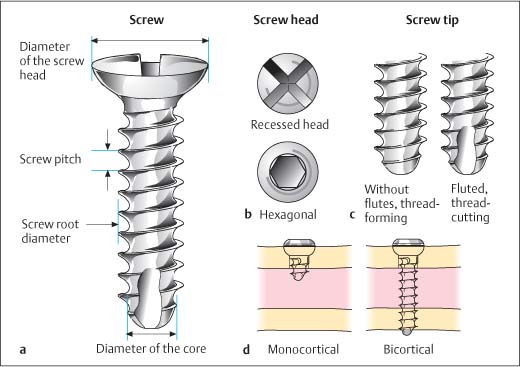
Screws
Screw Types
 threaded holes created by the screw itself;
 threaded holes produced by a tap.
 thread-cutting;
 thread-forming screws.
 Local compression loading when tightening the screw is high and thus there is a risk of microfractures occurring in the bone around the screw (Fig. 19.7c).
Screw Fixation
 In monocortical fixation only one side of the cortical bone is engaged; there is no contact with the opposite cortical bone segment. In the craniofacial region, monocortical fixation is only relevant for the mandible, as this is the only area with notable bicortical bone. Monocortical fixation allows fixation of screws even on the tooth-bearing mandible at the ideal localization, without damage to the roots of the teeth or the inferior alveolar nerve.
 In bicortical fixation, cortical bone, cancellous bone, and the opposite cortical bone are used for fixation of the screw. This type of fixation allows placement of compression plates, which can be done on the mandible and zygomaticofrontal suture. These are the only regions of the facial skeleton where the bone offers sufficient resistance to screw compression; elsewhere the bone is too thin.
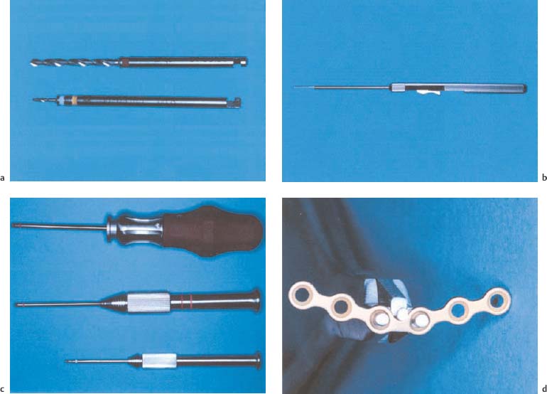
Screw Placement
Instruments for Placing Screws
Step-by-Step Screw Insertion Procedure
Plates
Types of Plates
 Straight plates, which are available with various numbers of holes, can be ideally adapted to bone contours in all three dimensions, given their three-dimensional malleability.
 Prebent plates (Y-, L-, T-, H-plates) also come with a varying number of holes, and are used when plates with a strong bending capacity are required, but bending with pliers might potentially damage the plate. When choosing the plate it must be remembered that the goal of osteosynthesis is to neutralize functional forces.
 Further plates include three-dimensional reconstruction plates, which are based on the principle of a force-neutralizing parallelogram and mesh, that can be used for reconstruction of comminuted fractures, for example, in the frontal sinus or orbital wall regions. Various manufacturers also offer plates for orbital wall reconstruction.
Instrumentation for Plate Adaptation
Steps in Plate Placement Procedure
Stay updated, free articles. Join our Telegram channel

Full access? Get Clinical Tree


