Purpose
To describe the inconsistencies in definition, application, and usage of the ocular reference axes (optical axis, visual axis, line of sight, pupillary axis, and topographic axis) and angles (angle kappa, lambda, and alpha) and to propose a precise, reproducible, clinically defined reference marker and axis for centration of refractive treatments and devices.
Design
Perspective.
Methods
Literature review of papers dealing with ocular reference axes, angles, and centration.
Results
The inconsistent definitions and usage of the current ocular axes, as derived from eye models, limit their clinical utility. With a clear understanding of Purkinje images and a defined alignment of the observer, light source/fixation target, and subject eye, the subject-fixated coaxially sighted corneal light reflex can be a clinically useful reference marker. The axis formed by connecting the subject-fixated coaxially sighted corneal light reflex and the fixation point, the subject-fixated coaxially sighted corneal light reflex axis, is independent of pupillary dilation and phakic status of the eye. The relationship of the subject-fixated coaxially sighted corneal light reflex axis to a refined definition of the visual axis without reference to nodal points, the foveal-fixation axis, is discussed. The displacement between the subject-fixated coaxially sighted corneal light reflex and pupil center is described not by an angle, but by a chord, here termed chord mu. The application of the subject-fixated coaxially sighted corneal light reflex to the surgical centration of refractive treatments and devices is discussed.
Conclusion
As a clinically defined reference marker, the subject-fixated coaxially sighted corneal light reflex avoids the shortcomings of current ocular axes for clinical application and may contribute to better consensus in the literature and improved patient outcomes.
Centration of intraocular lenses (IOLs) and refractive corneal treatments has always been important; but with the development of wavefront and topography-guided treatments, aspheric and multifocal IOLs, and corneal inlays, there has been a renewed interest in the matter. Any attempt at centration implies the identity of a reference center point. Without the proper frame of reference, descriptions of centration have limited reproducibility, utility, and relevance. This article examines the ocular axes and angles as described in the literature and suggests an alternative to applying the theoretical reference axes in the clinical setting. Reference markers that can be identified clinically are described, and a new clinically defined reference axis for preoperative measurement, intraoperative alignment, and postoperative assessment of refractive treatments and devices is presented.
The Reference Axes and Their Limitations
The human eye is not a centered optical system, as the fovea does not lie along the optical axis of the eye. The lens and cornea are slightly tilted and decentered relative to each other. These multiple unaligned refractive surfaces create challenges in both the optical description of the eye and the clinical determination of centration. In an attempt to study the optical properties of the eye, vision researches have created simplified models and described ocular reference axes to characterize these models. These axes have proven useful in modeling the eye and describing ocular alignment and motility issues. However, they lack the specificity and precision to be clinically useful in refractive corneal and intraocular surgery.
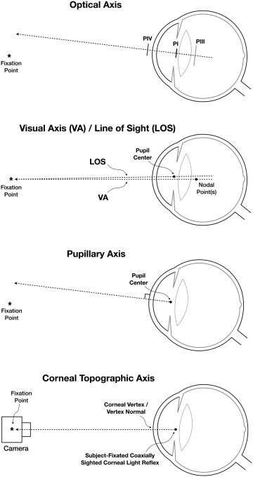
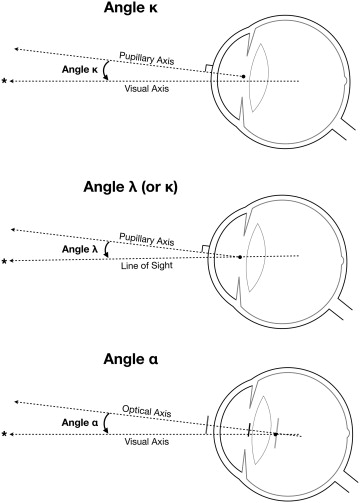
A review of the literature reveals that a number of ocular axes have been used to relate the optical structures of the eye, namely the optical axis, visual axis, line of sight, and pupillary axis ( Figure 1 , Table 1 ). In order to describe the relationships among these axes, various angles have been described, namely, angles kappa, lambda, and alpha ( Figure 2 , Table 2 ). Unfortunately, some concepts pertaining to ocular axes and angles are theoretical and cannot be applied clinically. Further, the terminology and definitions of ocular axes and angles have been used inconsistently and sometimes interchangeably.
| Ocular Axis | Alternate Names | Reference Point Outside Eye | Reference Point in Relation to Cornea | Reference Point in the Eye | Reference Point on the Retina |
|---|---|---|---|---|---|
| Optical axis | – | None | First Purkinje image a when the 3 Purkinje images are aligned | Purkinje images | None |
| Visual axis (2 nodal points) | Visual line, line of vision, line of regard, line of gaze, Gesichtslinie, principal line of direction | Fixation point | Undefined b | Two nodal points (anterior and posterior) | Fovea |
| Visual axis (1 nodal point) | – | Fixation point | Undefined b | One nodal point | Fovea |
| Visual axis (no nodal point) | Fixation point | Undefined b | None | Fovea | |
| Line of sight (reference point on retina described as fovea) | – | Fixation point | Corneal sighting center, c , visual center of the cornea d , | Entrance pupil center e | Fovea |
| Line of sight (reference point on the retina not described) | Sighting line, Visierlinie | Fixation point | Corneal sighting center, c visual center of the cornea d | Entrance pupil center e | None |
| Pupillary axis | Pupillary line, optic axis of Gullstrand | None | Orthogonal to cornea corresponding to the center of pupil | Entrance pupil center, center of curvature of the anterior surface of the cornea | None |
| Topographic axis | Videokeratograph optic axis, keratometry axis, device’s optical axis | Fixation point in the topographer | Corneal vertex/vertex normal/coaxially sighted corneal light reflex a , f | Corneal vertex/vertex normal/coaxially sighted corneal light reflex a , f , g | None |
| Subject-fixated coaxially sighted corneal light reflex axis | – | Fixation point | Subject-fixated coaxially sighted corneal light reflex a | Subject-fixated coaxially sighted corneal light reflex a , g | None |
| Foveal-fixation axis | – | Fixation point | Undefined | None | Fovea |
a First Purkinje image/subject-fixated coaxially sighted corneal light reflex originates from the cornea but is actually located inside of the eye.
b Referred to as the ophthalmometric pole by Le Grand and El Hage.
c Point corresponding to the pupillary center when sighted coaxially.
d Provided in dictionary of visual science, Cline et al., 1989.
e Lancaster stated that line of sight also passes through the center of rotation of the eye.
f When topographer is centered on the coaxially sighted corneal light reflex.
g Apparently directed toward the center of curvature of anterior surface of cornea, based on the principles of the reflection of light on the anterior surface of cornea.
| Angle/Chord Name | Alternative Names | Axes Involved | Subject-Fixated Coaxially Sighted Corneal Light Reflex Axis | Angle Subtended at e | |||
|---|---|---|---|---|---|---|---|
| Pupillary Axis | Visual Axis | Line of Sight | Optical Axis | ||||
| Alpha | Beta c , | – | Yes | – | Yes | – | Nodal point |
| Kappa a , b , | Delta d , | Yes | Yes | – | – | – | Unspecified |
| Lambda | – | Yes | – | Yes | – | – | Entrance pupil center |
| Mu | – | – | – | Yes | – | Yes | |
a Le Grand and Tabernaro described angle kappa as the angle between pupillary axis and line of sight, which is described as angle lambda elsewhere in the literature.
b Landolt and Landolt (1914), cited by Alvaro.
c Brubaker, in Duke-Elder (1932), cited by Alvaro.
d Howe, cited by Cords R, in: Schieck F, Bruckner A. Kurzes Handbuch der Ophthalmologie. Berlin: Julius Springer; 1930: vol. 3, p 468; further cited by Alvaro.
Optical Axis
Centered optical systems (eg, a telescope or microscope) have an optical axis, defined as the line passing through the geometric center of the optical elements. In a perfectly aligned optical system, the optical axis passes through the center of the object as well as the image; and it would be sufficient to describe the entire optical system. Since the eye is not a centered optical system, a true optical axis cannot be defined. Therefore, the eye’s optical axis is defined theoretically as a line that connects the 4 Purkinje images ( Figure 1 , Top). As such, there is no position or direction of the light source that enables the Purkinje images to be perfectly aligned. Nevertheless, if one minimizes the spread of these images, the corresponding direction of the source identifies the direction of the optical axis. Alternatively, some authors define the optical axis as the line of “best fit” through the centers of curvature of the “best fit” spheres to each surface, while others define it as the line connecting the geometric centers of the cornea and lens. It is important to note that the optical axis as thus defined is indeterminate when the lens is removed. In an aphakic eye, the first and second Purkinje images would define the optical axis; however, they are so close that it is not possible to connect them for clinical purposes. As such, the optical axis offers little clinical value for centration purposes. In the absence of a true optical axis, alternative axes may be considered.
Visual Axis
The concept of the visual axis is based on the line of direction—also known as richtungslinie—that originates from a point in space, passes through the anterior and posterior nodal points, and approaches an undefined location on the retina ( Figure 1 , Second from top). By its classical description, the visual axis is a broken line that connects the point of fixation with the first and second nodal points and the fovea. It travels from the fixation point to the first nodal point, exits from the second nodal point with the same angle, and intersects the fovea when the patient is fixating. To simplify the understanding of the visual axis, several publications describe a single (unified) nodal point; and others choose to omit the nodes from the description altogether, defining it instead as the line connecting the fixation point with the fovea.
Since it represents the actual path of light through the eye, the visual axis would be a logical candidate to use as the preferred reference axis for centration. Unfortunately, the visual axis cannot adequately serve this function for a number of reasons. The term “visual axis” is variably defined and used in the literature. Even if a consistent definition is used, the reference to nodal points is problematic in the clinical setting. Nodal points represent theoretical mathematical constructs with no corresponding anatomic landmarks, making clinical correlation of the visual axis in real eyes problematic. Eyes without perfect radial symmetry (eg, from astigmatism or coma) do not have nodal points. The concepts of nodal lines, nodal rays, nodal ellipses, nodal centers, and nodal axes have been proposed in these situations. Spherical and chromatic aberrations further complicate the definition. Without a consistent definition and without the ability to locate nodal points, the visual axis cannot be applied clinically.
Line of Sight
In lieu of these theoretically defined axes, it has been suggested that an anatomically defined axis would be more appropriately used in centration. The line of sight is defined in the terms of geometrical optics as a line joining the fixation point to the center of the entrance pupil ( Figure 1 , Second from top). By design, the line of sight is meant to correspond to the chief ray of a bundle of rays reaching the fovea. In principle, the visual axis as well as the line of sight should connect the fixation point to the fovea. The difference lies in the path of these 2 axes; while the visual axis passes through the 2 nodal points, the line of sight passes through the center of the pupil. That is, the line of sight goes toward the entrance pupil center in object space and appears to come from the exit pupil center in image space.
The biggest advantage of the line of sight is its anatomical definition, thus making it convenient to locate clinically. It has been suggested that the visual axis should be renamed the “nodal axis” and that the line of sight should be renamed the “visual axis,” thus adding to the confusion in nomenclature.
The biggest problem with using the line of sight clinically is that unless the pupil is perfectly centered, the line connecting the fixation point with the pupil center will not intersect the fovea. Further, the pupil center is not static; the pupil shifts with changes in pupil size owing to light and accommodation. Similarly, pharmacologic, congenital, pathologic, traumatic, and surgical causes of corectopia shift the pupil center such that the line joining the fixation point to the center of the entrance pupil would continue to a nonfoveal location on the retina. In aniridia, there is no pupil, so the line of sight definition becomes unusable.
Pupillary Axis
The pupillary axis is another anatomically defined axis; it is the line perpendicular to the cornea that passes through the center of the entrance pupil ( Figure 1 , Third from top). The pupillary axis can be easily located by centering the coaxially sighted corneal light reflex on the patient’s pupil. However, like the anatomically defined line of sight, the pupillary axis varies in location owing to the change in the center of the entrance pupil with variations in pupil size or with corectopia.
Corneal Topographic Axis
Not a traditional ocular axis, the corneal topographic axis (videokeratograph optical axis or keratometric axis) is essentially the optical axis of the topographer, defined in relation to the eye being examined. The point on the cornea corresponding to the coaxially sighted corneal light reflex has been described as the “corneal vertex” or “vertex normal” and is defined as the point of tangency of a plane perpendicular to the corneal topographer axis with the corneal surface. Therefore, the corneal topographic axis is the line connecting the fixation point in the topographer to the first Purkinje image when the patient is coaxially fixated with the optical axis of the device ( Figure 1 , Bottom). Based on the principles of reflection, the corneal topographic axis is apparently directed toward the center of curvature of the anterior surface of the cornea and thus is perpendicular (normal) to the cornea. It is also important to recognize that while the corneal topographic axis was initially described for the corneal topographer, fundamentally it applies to any ophthalmic imaging device or microscope with coaxial optics centered on the coaxially sighted corneal light reflex.
Ocular Landmarks for Positional Reference
Ocular axes are useful for describing and communicating spatial positioning within the model eye, but the literature contains a multiplicity of conflicting definitions and usages—particularly for the visual axis and the line of sight. Reference axes that were defined nearly a century ago, for hand-drawn eye models, simply lack applicability to clinical practice and intraocular surgery, during which corneas, lenses, and pupils are routinely manipulated. They do not provide sufficient correlation to actual identifiable structures and do not account for variations in the human eye.
A new clinically defined reference system is needed to provide an anchor around which discussions and studies of centration can be made. The definition should be conceptually precise and clinically applicable. Its name should denote the concepts that it embodies, and its use should not be encumbered by previous misapplications of its definition. It should also be irrespective of the pupil/iris configuration or lens status. This axis should be usable in the clinic, in surgery, in the laboratory, and in eye modeling. Anatomic reference landmarks for this axis should ideally be easily and reproducibly identifiable in all eyes.
Anatomic Structures as Reference Markers
The pupil and iris function as important reference markers owing to their easy visualization and importance in visual function. However, pupil size and location are always in flux, so precision and consistency cannot be achieved with this marker. The corneal apex and the lens apex could have relevance as reference markers, but changes in corneal shape (eg, from contact lenses, corneal scarring, or ectasia) and lens status (eg, after cataract extraction) limit their utility. Nonparaxial structures, such as the limbus and conjunctival vessels, could be considered as well. Unfortunately, there is no direct correlation of any anterior segment structure to vision and fixation.
Purkinje Reflections as Reference Markers
Until simultaneous visualization of both anterior segment structures and the fovea is possible, an effective way to correlate structure with function is to analyze how light interacts with these structures. Light reflecting off corneal and lenticular interfaces produces Purkinje reflections or Purkinje images. The location and appearance of each Purkinje image is determined both by the shape of the structure from which it originates and by the direction from which the eye is illuminated and viewed. Purkinje images therefore provide both anatomic and function/fixation information.
There are 4 Purkinje images, numbered sequentially PI to PIV, according to the interface from which they originate: the anterior and posterior surfaces of the cornea and the anterior and posterior surfaces of the lens/IOL ( Table 3 ). Since PII is much dimmer and nearly coincides with PI, only 3 Purkinje reflections (PI, PIII, and PIV) are typically seen. Although sequentially named, confusion as to the identity of the Purkinje images can arise because the Z-axis locations of the images do not correlate with the surface of their origin. Figure 3 shows the appearance of the Purkinje images in a pseudophakic subject through a surgical microscope ( Figure 3 , Top) and through a pupillometer ( Figure 3 , Bottom). In most pseudophakic subjects, PIII is seen behind the IOL while PIV is seen near the anterior surface of the cornea.
| Purkinje Image a | ||||
|---|---|---|---|---|
| PI | PII | PIII | PIV | |
| Source | Cornea, anterior surface | Cornea, posterior surface | Lens/IOL, anterior surface | Lens/IOL, posterior surface |
| Location | Lens-iris plane | Lens-iris plane | Anterior vitreous | Corneal surface |
| Relative size | Small | Small | Largest | Medium |
| Relative brightness | Bright | Dim | Dim to very bright | Medium |
| Orientation | Upright | Upright | Upright | Inverted |
| Movement with eye rotation | Slow | Slow | Rapid | Medium |
Stay updated, free articles. Join our Telegram channel

Full access? Get Clinical Tree


