Technical developments have taken place since the first endoscopes suitable for sialendoscopy appeared. Now, a variety of endoscopes are available. Ranging from rigid to flexible, each type has its own properties. Light sources, imaging, recording instrumentation, and other equipment used with the endoscopes facilitate or extend the range of their use. Experiences using different endoscopes in more than 300 endoscopies are discussed.
The diameter of salivary ducts sets a limit on the size of the instruments that can be used within them. The miniaturization of endoscopes finally allowed sialendoscopy to begin in 1988 ( Fig. 1 ). Multiple considerations are needed to adapt endoscopes to the salivary ducts and glands, including compact outer diameter, highest number of pixels, durability, effective cleaning and sterilization, large working channel for various instruments, ergonomic handling, and flexible maneuverability inside the duct system.
Types of endoscopes and their properties
Different types of endoscopes have emerged to meet the demands listed previously: flexible sialendoscopes, rigid sialendoscopes, and semiflexible sialendoscopes (compact and modular). Table 1 lists different models of sialendoscopes from the past and present. Box 1 lists the addresses of different producers and distributors for material usable for sialendoscopy. Each type of endoscope has its own clinical properties.
| Author, Year, no. of Pixels, Additional Information | Type of Endoscope | Compact/Modular/Steerable Flexible | Manufacturer/Distributor | Outer Diameter/mm | Diameter of the Working Channel/mm | Diameter of the Irrigation Channel/mm |
|---|---|---|---|---|---|---|
| Gundlach 1990 | Flexible | Unknown | Richard Wolf | 2 | 0.6 | Only one channel |
| Königsberger 1990 | Flexible | Steerable | Karl Storz | Unknown | >0.8 | |
| Katz 1991 | Flexible | Olympus (Tokyo, Japan) | 0.8 | None | ||
| Arzoz 1994 | Rigid | Unknown | Karl Storz | 2.3 | 1 | Only one channel |
| Gundlach 1994 | Flexible | 1.5 | 0.5 | |||
| Nahlieli 1994 | Rigid | Modular | Friatec (Mannheim, Germany) | 2.9 | None | 2.9–2.7 |
| Zenk 1994 | Flexible | Steerable | 1.6 | >0.4 | ||
| Iro 1995 | Flexible | Steerable | 1.6 | 0.6 | Only one channel | |
| Ito 1996 | Flexible | Clinical Supply (Japan) | 1.5 | 0.2 | ||
| Iro 1996 | Flexible | Steerable | 1.5–2.0 | >0.4 | 0.2 | |
| Arzoz 1996 | ? | Karl Storz | 2.1 | 1.0 | ||
| Yuasa 1997 | Flexible | Medical Science (Tokyo, Japan) | 0.8 | None | ||
| Yuasa 1997 | Rigid | Medical Science | 1.0 | None | ||
| Nahlieli 1997 | Rigid | 2.0 | 1.0 | |||
| Nahlieli 1997 | Rigid | 2.5 | 1.0 | |||
| Hopf 1998 | Flexible | Steerable | ? | 1.6 | 0.5 | Only one channel |
| Marchal 1998 | ? | ? | 0.9–1.6 | |||
| Nahlieli 1999 | Semirigid | Karl Storz | 1.3 | None | 1.3–1.0 | |
| Nahlieli 1999 | Semirigid | Karl Storz | 2.3 × 1.3 | 1.0 | 1.3–1.0 | |
| Kerr 2001 | Rigid | Richard Wolf | 1.5 | ? | ? | |
| Marchal 2001 | Flexible | Nonsteerable | 0.5–0.8 | None | None | |
| Marchal 2001 | Semirigid | Modular | Karl Storz | 1.3 | None | 1.3–1.0 |
| Marchal 2001 | Semirigid | Modular | Karl Storz | (2.67 mm 2 ) | 0.8 | + |
| Marchal 2001 | Semirigid | Modular | Karl Storz | (2.29 mm 2 ) | 0.8 | + |
| Chu 2003 | Rigid | 3.1 | + | |||
| Zenk 2004 6000 px | Semirigid | Compact | PolyDiagnost | 1.1 | 0.4 | + |
| Geisthoff 2007, 2008, 6000 px, a | Semirigid | Compact | Gyrus ACMI/Spiggle & Theis | 1.7 | 1.0 | 0.2 |
| Nahlieli 2007, Iro 2008, 6000 px, a | Semirigid | Compact | Karl Storz | 0.8 | – | 0.25 |
| Nahlieli 2007, Iro 2008, 6000 px, a | Semirigid | Compact | Karl Storz | 1.1 | 0.4 | 0.25 |
| Nahlieli 2007, Iro 2008, 6000 px, a | Semirigid | Compact | Karl Storz | 1.6 | 0.8 | 0.26 |
| 6000 px | Semirigid | Modular | PolyDiagnost | 0.9, 1.1, 1.6, 2.0 | One-joint working and irrigation channel also containing the optical system (0.53 mm) | |
| 10,000 px (one version with opening angle of 70° and one of 120°) | Semirigid | Modular | PolyDiagnost | 1.1, 1.6, 2.0 | One-joint working and irrigation channel also containing the optical system (0.9 mm) | |
| 30,000 px | Semirigid | Modular | PolyDiagnost | 1.6, 2.0 | One-joint working and irrigation channel also containing the optical system (1.2 mm) | |
| 6000 px, a | Semirigid | Compact | Spiggle & Theis | 0.9 | None | 0.26 |
| 6000 px, a | Semirigid | Compact | Spiggle & Theis | 1.0 | 0.41 | 0.2 |
| 6000 px, a | Semirigid | Compact | Spiggle & Theis | 1.2 | 0.62 | 0.2 |
| 6000 px, a | Semirigid | Compact | Spiggle & Theis | 1.4 | 0.62 | 0.3 |
| 6000 px | Flexible | Steerable | Spiggle & Theis | 1.3 | One-joint working and irrigation channel of 0.35 mm | |
- –
Almikro, Bad Krozingen, Germany ( www.almikro.de )
- –
Balaton, Warsaw, Poland
- –
Boston Scientific, Natick, Massachusetts ( www.bostonscientific.com )
- –
Cook Medical, Bloomington, Indiana ( www.cookmedical.com )
- –
Gyrus ACMI, Southborough, Massachusetts ( www.gyrusacmi.com ) (formerly Gyrus ACMI/Stuemer, Tuttlingen, Germany)
- –
Karl Storz, Tuttlingen, Germany ( www.karlstorz.com )
- –
PolyDiagnost, Pfaffenhofen, Germany ( www.polydiagnost.com )
- –
Richard Wolf, Knittlingen, Germany ( www.richard-wolf.com )
- –
Sialo Technology, Ashkelon, Israel ( www.sialotechnology.com )
- –
Spiggle & Theis, Overath, Germany ( www.spiggle-theis.com )
Flexible Endoscopes
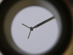
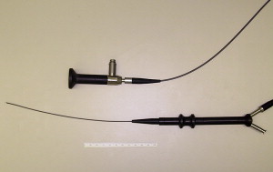
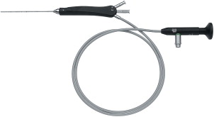
Flexible endoscopes are advantageous as it is possible to move them through ductal kinks and bends. Some of the flexible endoscopes can be steered, which is especially helpful when a certain branch has to be intubated (see Fig. 1; Figs. 2–5 ). Their use is atraumatic; however, a drawback is that only weak forces can be applied (eg, to surmount stenotic areas). Handling is often more difficult than for semirigid or rigid endoscopes. The success rate for normal stones seems to be lower than for semirigid endoscopes. Flexible endoscopes are fragile and have a short lifespan and it is not possible to autoclave them.
Rigid Endoscopes
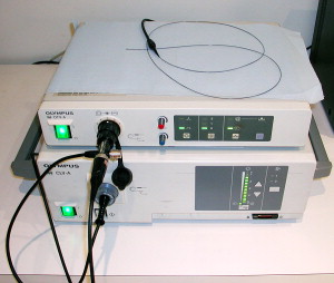
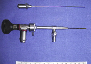
Most clinical endoscopes rely on a fiberoptic system for image transmission. Rigid endoscopes, however, use a pure lens system with superb optical qualities and better resolution. These endoscopes have larger diameters but are more stable ( Fig. 6 ). They can be autoclaved. The camera is fixed directly onto the ocular attached to the endoscope, resulting in a cumbersome handling.
Semirigid Endoscopes
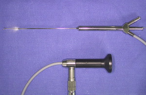
Semirigid endoscopes are a compromise between flexible and rigid endoscopes. The long, flexible, optical fiber connection for light and image transmission enables the decoupling of the examination probe from the rigid eyepiece. This means that work with semiflexible endoscopes can be performed with great freedom of movement and minimal effort while maintaining excellent precision. A modular and a compact construction type of semirigid endoscopes exist.
Semirigid Compact Endoscopes
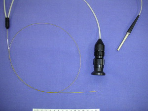
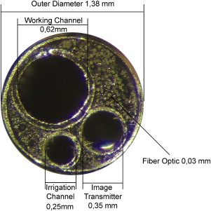
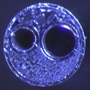
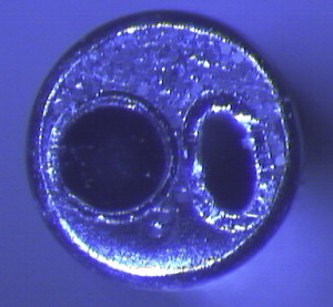
A typical therapeutic semirigid compact endoscope combines a fiber light transmission, a fiber image transmission, a working channel and an irrigation channel within one compact instrument ( Fig. 7 ). The outer tube covers, stabilizes, and protects all of the components resulting in a minimum outer diameter of the whole system. Fig. 8 shows the construction principle of the sheath of the examination probe of a semirigid compact endoscope and Figs. 9–11 show enlarged the tips of such endoscopes.

Semirigid Modular Endoscopes
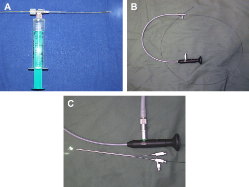
The optical fibers used for light and image transmission are combined into a single probe-like component ( Fig. 12 A, B). This can be used in combination with different sheaths (see Fig. 12 C). Using a small single sheath creates a diagnostic endoscope. The gap between optical system and the sheath’s outer wall is used as irrigation channel ( Fig. 13 ). A combination with a large single lumen sheath or a double-lumen sheath creates enough space to introduce different instruments ( Fig. 14 ).


In comparison with the compact versions, the ratio of the working channel to the total endoscope diameter is usually lower in modular endoscopes. The single therapeutic outer sheaths of modular endoscopes sometimes trap air, which can impair visualization by irrigating into the ducts. The modular systems, however, have two important advantages:
1. Economic advantage: only one optical system is necessary for a variety of procedures. The optical system is the most expensive part of the endoscope. By combining it with different sheaths, a versatile tool is created.
2. Hygienic advantage: compact endoscopes often have very thin irrigation channels. These are difficult to clean. Plasma sterilization may not be sufficient for these narrow channels, gas sterilization is often not available, and autoclaving can damage the endoscope. The probe-like optical system of modular endoscopes is easy to clean and is normally suitable for plasma sterilization. The channels of the different sheaths generally have larger diameters and the sheaths themselves are normally autoclavable or single use only.
Outer Diameter, Shape, Material, Maneuverability
The outer diameter is of paramount importance for the introduction of the scope and its advancement inside the narrow duct system. The endoscopes with diameters of approximately 1.5 mm and larger are sometimes not thin enough to accommodate the ducts and might not advance the pathology. In such cases, other approaches, such as sonographically controlled procedures, should be taken into consideration. Modular semiflexible endoscopes are produced with two different cross-sectional shapes: the round version conforms well with the round shape of the duct. The outer shape of a double tube uses the same perimeter of the duct for a lower cross-sectional area. The unused space between the two tubes, however, also has advantages: it can be used to flush fragments or debris with irrigation to clear the field of view. This space also allows for higher flow and passage of larger particles. For other large round endoscopes, it is sometimes necessary to interrupt endoscopy by removing the scope and massaging the gland to clear the duct system.
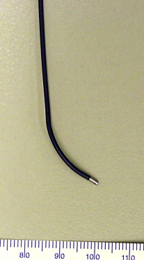
Some endoscopes are made from nitinol steel (see Fig. 12 B; Fig. 15 ), which is more flexible than regular steel and can be advantageous when following a curved duct. A more rigid system, however, is often easier to steer. Again, outer diameter also plays an important role here.

An interesting feature of one compact semirigid endoscope series (Marchal model, Karl Storz) is a slight bend in the endoscope shaft near its distal tip ( Fig. 16 ). This can make steering and selectively following branchings easier. The bend does reduce the usable diameter of the working channel, however, and prevents the use of straight, nonflexible instruments.

In most cases, the intraductal position of the endoscope tip can be easily seen by skin transillumination. Centimeter markings on the shaft, however, can help to assess exactly the tip’s position (Erlangen model, Karl Storz) ( Fig. 17 ).
Good maneuverability is also achieved by flexible, steerable, fine endoscopes. These endoscopes are mainly used for diagnostic purposes but do have a “working channel” in some models (Spiggle & Theis and Almikro) mainly for irrigation. Such models are of limited use for stone fragmentation and extraction as only fine baskets fit through the working channels. The use of laser fibers is limited as they are often not resistant to strong bending and break. The increase in combined endoscope approaches might give these instruments some more importance: a small, flexible, steerable endoscope is more likely to reach a stone in a curved duct system than a semirigid one. It can be used to mark the stone by the transillumination effect, so that it can be approached externally. Maneuvering a flexible steerable endoscope, however, often requires more skill and experience than a semirigid one.
Working Channel Diameter
The diameter of the working channel is of paramount importance for some therapeutic tasks. Table 1 gives an overview of the diameters of instruments used in therapeutic endoscopies. It is important to realize the effect of the diameter on the stability of the instruments. For instruments, such as forceps, balloons, or baskets, the cross-sectional area of a 0.4-mm diameter instrument is one quarter that of a 0.8-mm diameter instrument. The cross-sectional area of the latter one is 0.64 the size of a 1-mm diameter instrument. The rate of success and the risk of material fatigue breakage of the instruments are directly correlated with cross-sectional area. Additionally, the finer instruments are often more expensive. Alternatively, a large, stable instrument is of no use when it is too large to reach the relevant duct region. Sophisticated instruments in this respect are the so-called optical forceps, which are a combination of an outer sheath with an incorporated instrument (PolyDiagnost, Pfaffenhofen, Germany) ( Figs. 18 and 19 ). These instruments allow the effective use of forceps in combination with a small overall diameter of the whole instrument. Minor drawbacks of this system are that the forceps can impede vision during endoscope advancement. Additionally, a change of the instrument always means complete removal of the endoscope, a change-out of the instrument, and then its reinsertion.