4
Imaging of the Temporal Bone
The indications for presurgical assessment of the temporal bone by imaging are threefold: (1) to establish the histological diagnosis when not already done by tissue biopsy; (2) to determine the size and extent of the pathological process; and (3) to identify the lesion’s relationship or possible involvement with critical anatomical structures, such as the carotid artery, jugular vein, facial nerve, and meninges. Computed tomography (CT), magnetic resonance (MR), and angiography are the techniques used to study the temporal bone and auditory-vestibular pathways. CT is the method of choice for the assessment of bony structures. MR is superior for soft tissue structures or masses within or adjacent to bone.
Computed Tomography
Helical or spiral CT has replaced conventional CT. This technique allows rapid acquisition of volumetric data of the part of the body under investigation: 50 to 60 submillimeter sections of the entire temporal bone are acquired in less than 1 minute. New multislice scanners are even faster: the 16-slice CT unit is able to acquire 32 half-millimeter isotrophic images in 1 second. Because the voxel size is nearly equal in all three dimensions, image quality is also identical for axial, coronal, and sagittal images.
The axial projection is obtained with the patient supine and the canthomeatal line perpendicular to the tabletop (Fig. 4–1A, B). Direct coronal sections are obtained with the head overextended and the gantry of the scanner tilted so as to compensate for an incomplete extension of the head (Fig. 4–1C, D). These two projections are complementary because the axial delineates the anterior and posterior aspects and dimensions, whereas the coronal demonstrates the superior and inferior boundaries1.
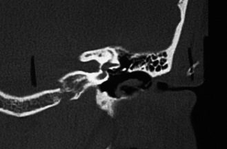
Sagittal and oblique projections can be obtained by computer reformations of the raw data. Sagittal sections are particularly useful for the assessment of the vestibular aqueduct (Fig. 4–1E) and mastoid segment of the facial canal. Oblique sections perpendicular to the long axis of the petrous pyramid are indicated for the assessment of the superior semicircular canal to rule out a possible fistula of the canal (Fig. 4–1F). CT provides excellent bony details and good demonstration of soft tissue densities within the air spaces of the temporal bone but very limited identification of the substance producing the abnormal density.
Magnetic Resonance
MR provides a far more precise assessment of the type of tissue within the air spaces and abnormal cavities of the temporal bone. Unlike CT and other radiographic techniques where pictures are related to the differential absorption of the x-ray beam by different tissues, MR images are obtained by the interaction of hydrogen nuclei or protons, high magnetic fields, and radio-frequency pulses. The intensity of the MR signal to be converted to imaging data depends on the concentration or density of free hydrogen nuclei in the tissue under examination and on two magnetic relaxation times, T1 and T2, which are tissue specific. Fat and body fluids contain large amounts of free protons and therefore emit strong signals that are displayed as bright areas. Air, bone, and calcifications appear as dark areas because they contain few free protons and therefore emit a weak MR signal. Pathological processes are recognized when the proton density and relaxation times of the involved tissue differ from those of the normal tissue.
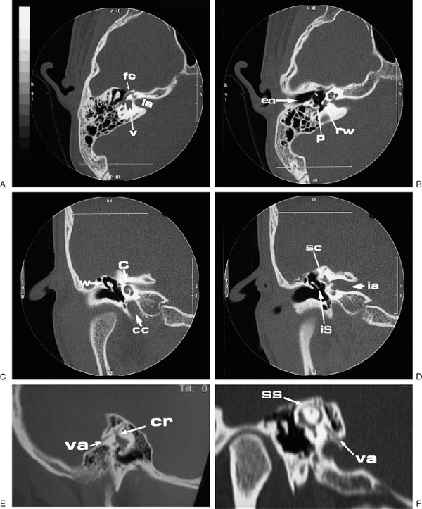
FIGURE 4–1 Computed tomographic sections of a normal temporal bone. (A, B) Axial; (C, D) coronal; (E) sagittal; and (F) oblique sections. C, cochlea; CC, carotid canal; CR, common crus, EA, external auditory canal; FC, facial nerve; IA, internal auditory canal; IS, incudostapedial joint; P, pyramidal eminence; RW, round window; SC, semicircular canals; SS, superior semicircular canal; V, vestibule; VA, vestibular aqueduct; W, lateral attic wall.
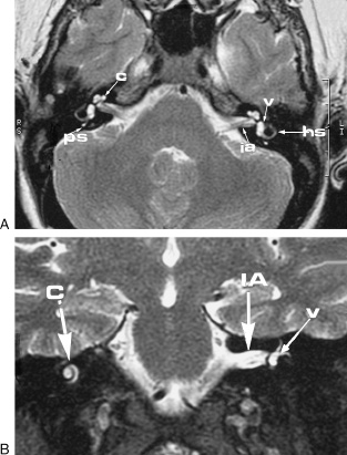
FIGURE 4–2 (A) Axial and (B) coronal magnetic resonance images of a normal temporal bone. C, cochlea; HS, horizontal semicircular canal; IA, internal auditory canal; PS, posterior semicircular canal; V, vestibule.
The study is performed with the patient supine as for the axial CT images. Different projections are obtained by changing the orientation of the magnetic field gradients without moving the patient’s head (Figs. 4-2A, B, 4-3, and 4-4).The use of ferromagnetic contrast agents has improved the recognition and differentiation of pathological processes.
Angiography
Selective angiography performed by the Seldinger technique remains the gold standard for the visualization of small vessels, both intra- and extracranial. Subtraction is necessary to delineate the vessels that are otherwise obscured by the density of the surrounding structures. Today this invasive procedure is seldom performed for the diagnosis of vascular tumors or anomalies but remains mandatory for identifying the feeding vessels of the lesion prior to embolization or surgical ligation.
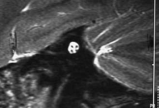
FIGURE 4–3 Magnetic resonance image of the internal auditory canal: sagittal section clearly showing the facial, auditory, and vestibular nerves.
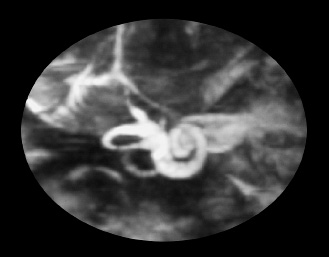
FIGURE 4–4 Three-dimensional reconstruction of the membranous labyrinth.
MR angiography (MRA) and CT angiography (CTA) are noninvasive studies that allow excellent detailed views of the vessels and vascular abnormalities. Gradient echo techniques and flow-encoded gradients have enabled the development of MRA. Unlike CTA, MRA is an imaging study of the vessels only, as the other tissues are nulled by the radiofrequency pulse sequences, and it can be performed without the use of contrast (Fig. 4–5).Following the imaging, two-dimensional (2D) reformatted images are usually created in multiple planes. Three-dimensional (3D) or volume rendered reconstructions can also be obtained, but the work of 3D reformatting is quite extensive and requires a separate work station.
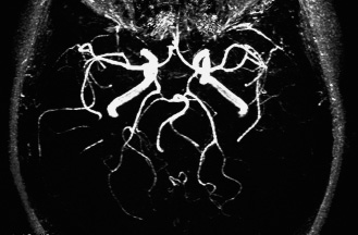
FIGURE 4–5 Magnetic resonance angiography of the brain showing carotid and basilar arteries and their main branches.
The introduction of ultrafast CT has opened the possibility of obtaining excellent angiographic images. In CTA the rapid acquisition of multiple images makes it possible to follow the intravenously injected bolus of contrast through the arteries and veins of the area under investigation. The obtained source images provide the data for 2D and 3D reformation in multiple planes (Fig. 4–6).
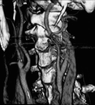
FIGURE 4–6 Computed tomographic angiography of the neck clearly showing the carotid arteries and their bifurcation.
MRA of the intracranial vasculature has been particularly useful in the diagnosis of aneurysms in the region of the circle of Willis (Fig. 4–7A,B) and arteriovenous malformations. CTA and MRA of the neck provide useful information on the patency of the carotid and vertebral arteries.
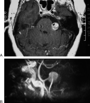
FIGURE 4–7 Aneurysm, left vertebral artery. (A) Axial magnetic resonance T1 section after contrast showing a bright mass in the left cerebellopontine cistern. The area of signal void within the enhancing lesion represents the patent lumen of the aneurysm, otherwise filled by a large blood clot. (B) Magnetic resonance angiography confirms the presence of an aneurysm arising from the left vertebral artery.
■ Imaging Finds for Pathological Conditions by Anatomical Location
The pathology of the temporal bone is reviewed in this chapter by anatomical location: mastoid, external auditory canal, middle ear, inner ear, oval window and labyrinthine capsule, petrous pyramid, and internal auditory canal and facial nerve.
Mastoid
The development of the mastoid varies from person to person and, to a lesser degree, from side to side of the same individual (Fig. 4–8). The pneumatization may be limited to a single antral cell or extend into the mastoid tip, temporal squama, and even the adjacent zygoma and occipital bone. The nonpneumatized mastoid process may consist of solid bone or may contain spongy diploic spaces filled with fatty marrow. On MR imaging (MRI), compact bone will produce no signal and will appear as an area of signal void. Instead, fatty marrow will appear as an area of high signal in the T1 image, which decreases in the T2 and should not be confused with fluid or other pathological processes.
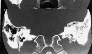
FIGURE 4–8 Asymmetric pneumatization of the mastoids.
Developmental variations occur in the mastoid, which should be recognized prior to surgery so as to avoid possible serious complications. In the axial CT images a shallow groove is usually seen in the posterior aspect of the mastoid produced by the lateral or sigmoid sinus. Occasionally, the sinus courses more anteriorly and produces a deep groove that may reach the posterior wall of the external auditory canal (Fig. 4–9). In the coronal CT images, the tegmen of the mastoid and attic is well seen as it passes in a horizontal plane slightly lower than the arcuate eminence. In cases of canal atresia or scanty development of the mastoid, the tegmen may be depressed, and the middle cranial fossa deepens to form a deep groove lateral to the attic and to the labyrinth (Fig. 4–10).
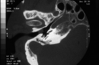
FIGURE 4–9 Anterior protrusion of the lateral sinus.
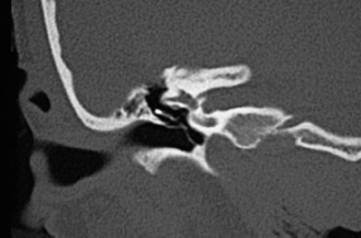
FIGURE 4–10 Low-lying dura.
The imaging findings of acute mastoiditis vary with the stage and severity of the process. In the early stage the mastoid cells appear cloudy, and air-fluid levels are often observed within the cells. As the infection progresses, the mastoid trabeculae become first deminer-alized and then destroyed with formation of coalescent areas of suppuration (Fig. 4–11).On MRI, pus can usually be differentiated from clear fluid because it has a slightly higher signal in the T1. If the process is not controlled, the mastoid cortex may be eroded with the formation of subperiosteal abscess, or the sinus plate is eroded (Fig. 4–11), which may lead to thrombophlebitis of the sigmoid sinus and to epidural and brain abscesses.
Chronic mastoiditis is the result of lower-virulence germs or of an incompletely controlled acute infection. If the infection occurs in childhood, the mastoid is poorly pneumatized, the mastoid antrum and developed air cells become partially or totally opacified, and the trabeculae become progressively thickened, which may lead to complete obliteration of the air cells (sclerotic mastoiditis). In children, eosinophilic granuloma and rhabdomyosarcoma produce extensive lytic lesions difficult to differentiate by imaging but usually quite different in their clinical course. The mastoid trabecular pattern is completely erased, and the mastoid cortex is thinned out, destroyed, or expanded. The external auditory canal and middle ear are usually involved with the progression of the disease.
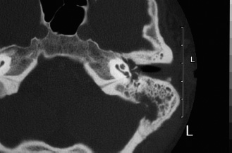
FIGURE 4–11 Coalescent mastoiditis with erosion of the sinus plate and thrombosis of the sigmoid sinus.
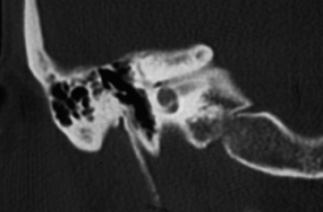
FIGURE 4–12 Agenesis of the right external auditory canal. The middle ear is aerated, but the ossicular chain is grossly hypoplastic and malformed.
External Auditory Canal
CT is the study of choice for lesions limited to the external auditory canal or involving the adjacent temporal bone, but MRI becomes preferable for pathological processes extending or arising outside the confines of the temporal bone.
Congenital malformations of the external auditory canal are not uncommon and are usually associated with microtia of varying degrees, although no direct correlation exists between the two abnormalities. The degree of atresia of the external auditory canal varies from complete agenesis ((Fig. 4–12) to stenosis and to closure of the canal lumen by a bony plate of variable thickness (Fig. 4–13). The soft tissue tag and pit noticeable in atretic ears often bear no topographic relationship to the underlying mastoid and middle ear.
Necrotizing (malignant) external otitis is an acute osteomyelitis arising in the external auditory canal and rapidly spreading to other portions of the temporal bone and adjacent areas. The infection is caused by the Pseudomonas bacterium and occurs in debilitated, diabetic, and immunosuppressed patients. The early CT findings are stenosis of the canal lumen due to soft tissue swelling and erosion of the canal walls (Fig. 4–14), particularly of its floor. The infection then spreads along the undersurface of the temporal bone to involve the facial nerve at the stylomastoid foramen, resulting in facial paralysis. If the infection is not controlled the process spreads to the temporomandibular fossa, mastoid, middle ear, and petrous pyramid.
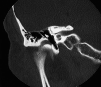
FIGURE 4–13 Stenosis and lateral bony atresia of the right external auditory canal.
External auditory canal cholesteatoma occurs in two different forms. The first, keratosis obliterans, is caused by blockage of the canal with accumulation of epithelial debris and consequent formation of a soft tissue mass filling and expanding the canal medial to the site of obstruction (Fig. 4–15). The second form, invasive keratitis, results from areas of dyskeratosis in the canal floor causing localized bony erosion. The lesion is first covered by epithelial debris, which then sloughs off, leaving exposed bone. Large cholesteatomas erode the annulus and extend into the middle ear cavity.
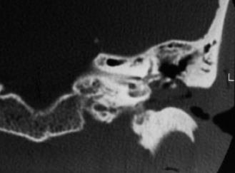
FIGURE 4–14 Necrotizing external otitis. The external auditory canal is almost completely obstructed by soft tissue. The superior wall of the canal and the scutum are eroded as the process extends into the middle ear.
Osteomas are frequent in the external auditory canal, where they cause stenosis of the canal lumen (Fig. 4–16).
Carcinoma of the temporal bone usually arises in the external auditory canal. The imaging findings vary with the extent of the lesion. The canal walls become eroded, then the tumor may spread anteriorly into the tempo-romandibular joint, posteriorly into the mastoid, where it reaches the facial canal, and medially into the middle ear (Fig. 4–17), jugular fossa, petrous pyramid, and labyrinth.