Today most cochlear implant users achieve above 80% on standard speech recognition in quiet testing, and enjoy excellent device reliability. Despite such success, conventional designs often fail to provide the frequency resolution required for complex listening tasks. Furthermore, performance variability remains a vexing problem, with a select group of patients performing poorly despite using the most recent technologies and processing strategies. This article provides a brief history of the development of cochlear implant technologies, reviews current implant systems from all 3 major manufacturers, examines recently devised strategies aimed at improving device performance, and discusses potential future developments.
“All of us in implant research have hoped that somehow we would hit upon an electrode configuration or external processing scheme that would suddenly give our patients normal hearing. This perfect device has eluded the many research teams that have formed around the world. Therefore, we have concentrated on determining whether one implant is a little better than another. However, differences in performance may be due as much to individual variation as to variations in the devices… I am not discouraged. I am simply much wiser about cochlear implants. Twenty years ago I thought implants could be developed and widely applied in 4–5 years. Let us recognize that we have at least another 20 years of painful, step-by-small-step development if we are to continue to improve the cochlear implant.” —William F. House, MD, 1986
Few modern medical advances better exemplify the success that can be achieved through synchronous technological and surgical innovations than the cochlear implant (CI). Despite early criticism from the scientific community, it was through persevering collaboration between pioneering surgeons, clinical scientists, and engineers that early prototype designs came to fruition. What once only provided individuals with the crude sensation of sound, allowing for improvements in lipreading ability, the majority of patients are now achieving more than 80% on open-set speech recognition tasks. Today nearly 200,000 patients have undergone implantation worldwide, and cochlear implantation has become the standard of care for hearing rehabilitation in patients with severe to profound sensorineural hearing loss (SNHL).
Despite tremendous progress over the last quarter-century there remains room for improvement. Looking forward, the ideal device should emulate natural hearing in both quiet and complex noise conditions, demonstrate safe long-term reliability, and overcome issues with user performance variance; the hardware package must be durable, energy efficient, and boast an inconspicuous design. In this article the authors provide a brief history of the development behind the CI, discuss the current state of available technologies, and review potential future directions both near-term and long-term.
History of cochlear implant development
In 1790, Allesandro Volta first discovered that electrical stimulation of the auditory system could create the perception of sound when he placed metal rods in his own ears. After activating a ∼50-V circuit he experienced the sensation of “une recousse dans la tete” (“a boom within the head”), followed by a sound likened to that of boiling thick paste. During the early 1900s, further research laid the theoretical groundwork for future implant development, realizing that electrical current may create auditory percepts through direct stimulation of the cochlear nerve.
In 1957, a French otologist (Djourno) and physicist (Eyriés) provided the first detailed description of the effects of directly stimulating the auditory nerve in a deaf patient. During a radical resection for extensive bilateral cholesteatomas the right cochlear and facial nerves were sacrificed. With a subsequent surgery aimed at grafting the severed facial nerve, an electrode was applied to the proximal auditory nerve stump. When a current was applied the patient was able to discern differences in intensity and frequency, and over time was able to appreciate environmental sounds and recognize several simple words.
In the early 1960s several independent groups in the United States began implanting patients with prototype CI designs. In 1964, Blair Simmons from Stanford University implanted 6 stainless-steel electrodes into the cochlear nerve through the modiolus. William House in Los Angeles fortuitously learned of Djourno and Eyriés’ earlier work when one of his patients provided an article describing their results. Inspired by this account, in 1961 House implanted several gold electrodes, and in 1965 he teamed up with engineer Jack Urban to develop devices that might weather long-term use. In 1972, House introduced a commercially available implant with a wearable signal processor, platinum electrodes, and an induction coil system, and in 1973 he began the first phase of clinical trials.
Despite these early triumphs there was growing skepticism from other experts in the field, and the concept of achieving meaningful audiologic rehabilitation in deaf patients through electrical stimulation was condemned by the scientific community. It was not until 1977, after a National Institutes of Health commissioned investigatory team evaluated the first 13 single-channel electrode implantees, that the concept of cochlear implantation became legitimized. In his report, Robert Bilger confirmed that CI technology could afford improved hearing with enhanced lipreading, recognition of limited environmental sounds, and improved control of voice modulation with minimal patient risk.
During this time, Graeme Clark in Sydney, Australia developed a multichannel banded electrode and implanted his first patient in 1978, which afforded limited open-set speech recognition. Early success prompted interest from the Australian national government and a partnership was formed between the University of Melbourne, the Australian government, and a medical equipment company, Nucleus Ltd, which led to the establishment of Cochlear Ltd.
Early CI commercial device development benefited from advancements in computer microcircuit fabrication and implantable pacemaker technologies. On November 26, 1984, the first single-channel CI (House/3 M) was approved by the Food and Drug Administration (FDA) for implantation in adult patients with profound postlingual deafness. Owing to improved spectral perception and open-set speech recognition, the multichannel design soon replaced earlier single-channel devices.
Early innovations including the addition of the multichannel electrode and increasingly sophisticated signal-processing strategies have revolutionized the CI industry. However, within the last 10 years we have seen a plateau in speech recognition performance in quiet, and our attention has thus shifted toward overcoming more difficult listening tasks including performance in background noise, sound localization, and music appreciation, in the quest to more perfectly replicate normal hearing.
Current implant systems
Overview
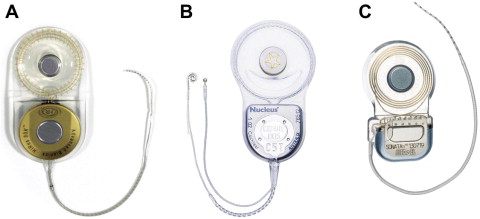
There are currently 3 manufacturers of CIs that have FDA approval: Advanced Bionics Corporation (Valencia, CA, USA), Cochlear Corporation (Lane Cove, Australia), and Med-El GmbH (Innsbruck, Austria) ( Fig. 1 ). Despite variations in component design and sound-processing strategies, device performance is generally comparable between all 3 implant manufacturers when evaluating present-day designs.
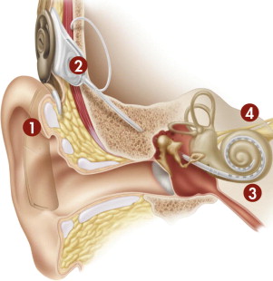
Virtually all modern CIs share a set of common functional components. In its most fundamental form, the CI is a transducer that changes acoustic energy into an electrical signal, which is used to stimulate surviving spiral ganglion cells of the auditory nerve ( Fig. 2 ). Despite the loss of stimulating inner hair cells from associated disease processes, the cochlea is able to preserve sufficient numbers of spiral ganglion cells, which are critical to successful implant stimulation.
The external hardware comprises 3 separate components: the microphone, the sound processor, and the transmitter. The microphone is generally placed on or near the earhook; it receives natural acoustic information and converts it to an analog electrical signal that is subsequently sent to the behind-the-ear (BTE) sound processor. The sound processor in turn alters the signal to a format that is meaningful to the receiving cochlea and central nervous system through the processes of amplification, compression, and filtering. In modern digital sound processors, this process also involves an analog-to-digital conversion. The processed signal, which contains temporal and spatial patterns of stimulation, is then encoded and sent through a transcutaneous transmitter, generally by way of radiofrequency, to the implanted device.
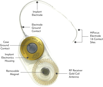
The implanted package contains the magnet, telemetry coil, and a hermetically sealed electronics package. Once received, the data are decoded and can be sent to individual channels according to the signal processing strategy that is used. The fantail protects the transmitting electrodes as they exit the hermetically sealed housing. The active lead contains individual wires that transmit data for each respective channel along the implanted multichannel electrode, while a second extracochlear lead serves as the ground electrode and is only used with the monopolar electrode configuration ( Fig. 3 ). Because the spiral ganglion cells located in Rosenthal’s canal are the intended site of stimulation, the ideal electrode location is near the modiolus in the scala tympani.
Electrical stimulation of the auditory system requires the completion of a full circuit loop whereby one electrode along the implanted array serves as the “active” electrode and a second serves as the “inactive” or return electrode. Monopolar stimulation is the most commonly used strategy in modern CI designs and generally incorporates a remotely located extracochlear reference electrode, which is either located on the case of the receiver-stimulator package or placed under the temporalis muscle. In many cases, the current return path for the monopolar electrode configuration is divided equally between the case ground and the remote ground placed under the temporalis muscle. A pseudomonopolar electrode configuration can also be used, which allows for the most basal electrode, or band electrode (Advanced Bionics Corp), to serve as the ground. Bipolar stimulation, on the other hand, uses a neighboring electrode within the implanted array as the return. Monopolar stimulation has been found to perform on par or better than bipolar strategies while simultaneously providing more efficient power use and reducing the likelihood of exceeding the limits of voltage compliance for any given electrode along the array.
Device Designs
This section provides a description of the most recent device and electrode designs available from the 3 major manufacturers ( Tables 1–3 ), reviews several notable advances with respect to electrode design and use, and finally discussed potential future electrode design options. While there are multiple driving concepts that continually influence and shape the evolution of electrode design, for the sake of brevity the authors focus their discussion on the electrode-nerve interface and the incorporation of trauma-minimizing strategies.
| Category | Subcategory | Advanced Bionics Corp: HR90K | Cochlear Corp: Nucleus 5 | Med-El GmbH: Sonata ti100 |
|---|---|---|---|---|
| Dimensions, mm (max. length × width × thickness) | Receiver-stimulator package (overall) | 56 × 28 × 5.5 | 50.5 × 30.5 × 3.9 | 45.7 × 24.8 × 5.9 |
| Titanium housing | 20 × 20 × 5.5 | 22.3 × 23.5 × 3.9 | 17.4 × 24.8 × 5.9 | |
| Telemetry coil | 28 × 28 × 3.0 | 28.2 × 30.5 × 3.3 | 28.3 × 24.8 × 3.7 | |
| Weight, g | Receiver-stimulator package | 12 | 8.8 | 8.6 |
| Case impact resistance, J | Receiver-stimulator package | Up to 6 | Up to 2.5 | Not available |
| Diagnostic testing | Impedance level testing | Yes | Yes | Yes |
| Neural telemetry | Yes | Yes | Yes | |
| Electrically evoked stapedius reflex threshold | Yes | Yes | Yes | |
| Electrically evoked auditory brainstem response | Yes | Yes | Yes | |
| Electronics platform | Maximum stimulation rate | Up to 83,000 pps | Up to 31,500 pps | Up to 50,700 pps |
| Current range | 0–1.75 mA | 0–1.75 mA | 0–1.2 mA | |
| Current source (simultaneous stimulation capable) | Multiple (Yes) | Single (No) | Multiple (Yes) |
| Category | Advanced Bionics Corp: Harmony | Cochlear Corp: Nucleus 5 (CP810) | Med-El GmbH: OPUS 2 |
|---|---|---|---|
| Dimensions, mm (max. height × thickness) | 54 × 13 | 51 × 9 | 57.8 × 8.7 |
| Weight, g (including lightest battery option) | 13.5 | 10.9 | 10.1 |
| Listening modes | BTE Omni Mic, T-Mic, Telecoil | BTE Omni Mic, SmartSound BEAM (adaptive [Focus] and fixed [Zoom] directionality), Telecoil | BTE Omni Mic, Telecoil |
| Frequency range, Hz | 150–8000 | 100–8000 | 70–8500 |
| Input dynamic range, dB | Up to 80 | Up to 75 | 75 |
| Number of programs that can be stored | 3 | 4 | 4 |
| Bilateral control with single remote | No | Yes | Yes |
| Water-resistant rating | No | Yes, IP44 & IP57 | No |
| Conventional-Length Electrode Designs | |||||
|---|---|---|---|---|---|
| Feature | Advanced Bionics Corp: HiFocus Helix | Advanced Bionics Corp: HiFocus 1j | Cochlear Corp: Contour Advance with AOS | Cochlear Corp: Straight Electrode (ST) | Med-El GmbH: Standard (H) |
| Number of active electrodes | 16 half bands | 16 half bands | 22 half bands | 22 full bands | 12 paired (total 24) |
| Number of potential pitch percepts | 460 | 460 | 161 | 161 | Not available |
| Proximal array diameter, mm | 1.1 | 0.8 | 0.8 | 0.6 | 1.27 |
| Distal array diameter, mm | 0.6 | 0.4 | 0.5 (Softip 0.2) | 0.4 | 0.5 |
| Recommended cochleostomy size, mm | 1.2–1.6 | 1.5–2.0 | 1.2–1.5 | 1.0–1.4 | 1.3 |
| Shape | Perimodiolar | Straight | Perimodiolar | Straight | Straight |
| Stylet incorporation | Yes | No | Yes | No | No |
| Total length, mm | 24.5 | 25 | 17.8 | 23.9 | 31.5 |
| Total length of active electrodes, mm | 13 | 17 | 14.4 | 16.4 | 26.4 |
| Spacing between contacts, mm | 0.85 | 1.1 | 0.31–0.42 | 0.45 | 2.4 |
| Approximate angular insertion depth | 360°–420° | 400°–500° | 360°–450° | 270°–390° | 540°–630° |
| Electroacoustic (Short) Electrode Designs | |||
|---|---|---|---|
| Feature | Cochlear Corp: Hybrid S(8) | Cochlear Corp: Hybrid L | MED-EL GmbH: Flex EAS |
| Number of active electrodes | 6 Half bands | 22 Half bands | 7 Basal pairs + 5 single apical |
| Proximal array diameter, mm | 0.4 × 0.25 | 0.55 × 0.4 | 0.8 × 0.78 |
| Distal array diameter, mm | 0.4 × 0.25 | 0.35 × 0.25 | 0.58 × 0.35 |
| Recommended cochleostomy size, mm | 0.5–0.7 | 0.6–1.0 | 0.8 |
| Shape | Straight | Straight | Straight |
| Stylet incorporation | No | No | No |
| Total length, mm | 10 | 16 | 26 |
| Total length of active electrodes, mm | 4.3 | 15 | 20.9 |
| Spacing between contacts, mm | 0.45 | 0.75 | 1.9 |
| Approximate angular insertion depth | 180°–205° | 230°–290° | 330°–390° |
Current device and electrode designs
The Nucleus 24 series devices (Cochlear Corp) all feature a single current source with 22 intracochlear electrode contacts housed within a silicone carrier. Electrode contacts are pure platinum with platinum-iridium wires, and the receiver-stimulator is housed in a hermetically sealed titanium case. The 24 M had a straight configuration and contained individual banded electrodes (exposed 360°) with 10 inactive proximal “stiffening rings” to facilitate insertion. The CI24RCS first introduced the curved or “perimodiolar” design and insertion stylet (Contour). It contained 22 half-band electrodes (exposed 180° facing the modiolar side); the 10 stiffening rings seen on the earlier 24 M model were replaced by 3 silicone rings. The Nucleus CI24RCA first used the Advance Off-Stylet (AOS) system and added a tapered soft tip (Softip) to decrease trauma during insertion (Contour Advance). The subsequent 24RE (ie, Freedom) device has a smaller size, but otherwise keeps a similar design to prior models. The recently added Nucleus 5 implant improves on the receiver-stimulator size in terms of both its overall footprint size and thickness, but again maintains an identical electrode design to previous generation implants. Cochlear Corp also manufactures a double array (Nucleus 24 Double Array) for use in patients with significant cochlear ossification; a basal array of 11 electrodes can be inserted through a standard cochleostomy location and a second apical array containing 11 additional electrodes can be inserted into the second turn of the cochlea. The previously mentioned thinner straight (ST) array remains available, and may be useful in patients with partially ossified cochleae or revision cases where a straight array was first used.
The HR90 K (Advanced Bionics Corp) implants similarly feature a hermetically sealed titanium housing and a telemetry coil encased in silastic. There are currently two electrode options, each incorporating 16 independent current sources corresponding to 16 intracochlear electrodes housed in a silicone carrier. The HiFocus Helix electrode uses a 24.5-mm perimodiolar design with stylet and houses 16 planar contacts arranged along the medial surface of the electrode. The HiFocus 1j uses a straight design, and is slightly thinner and longer than the HiFocus Helix. Both electrodes use a unique insertion tool to reduce trauma and decrease the risk of tip fold over and electrode buckling.
Med-El’s Sonata ti100 also incorporates a titanium device housing and platinum-iridium electrode wires. The standard array incorporates 12 independent current sources with 24 electrodes featured as 12 twin surfaces contained within a silicone carrier. Med-El also offers the Pulsar ti100 device, with an identical electronics package to the Sonata ti100, but uses impact-resistant ceramic casing with a smaller overall size and thickness (uniformly 4 mm thick). The most commonly used Standard (H) array uses a straight design with 2.4-mm spacing between the electrodes, which are distributed over 26.4 mm for an estimated insertion depth of 31.5 mm. Med-El also offers other additional electrode options; those currently with FDA approval include:
- 1.
Medium (M), with the same 12-electrode configuration with 1.9-mm spacing over 20.9 mm, designed for those with considerable low-frequency hearing or in patients for whom a deeper insertion is not desired (eg, cochlear malformations)
- 2.
Compressed (S), with the identical 12 paired electrodes but with 1.1-mm spacing between contacts along 12.1 mm, designed for patients with cochlear malformations or partial ossification
- 3.
Split electrode array (GB), where one lead contains 5 electrode pairs and the other 7 electrode pairs each with 1.1-mm spacing, designed for patients with extensive cochlear ossification.
Minimizing trauma
With early CI systems it was believed that electrode insertion resulted in significant intracochlear trauma, thereby irreversibly destroying all residual hearing. However, over the last 2 decades we have witnessed improved rates of hearing preservation following implantation through the use of modified surgical techniques and electrode design. Within last 10 years there has been a paradigm shift toward the development of minimally traumatic electrode designs and soft surgical techniques to improve performance and expand candidacy criteria.
There are at least 3 common mechanisms responsible for acute mechanical inner ear injury during electrode insertion. The electrode may be inserted through a cochleostomy created anteroinferior to the round window, or alternatively may be placed through the round window membrane. The round window membrane sits in close proximity to the vertically aligned osseous spiral lamina, and during electrode insertion it is possible to fracture the osseous spiral lamina or spiral ligament. A second common method of injury involves traumatic abutment of the lateral scalar structures at the first basal turn of the cochlea and beyond. Most electrodes demonstrate a relatively straight mid-scalar course down the basal turn of the cochlea. However, once reaching the first turn most electrodes abut the lateral wall and are forced toward the basilar membrane. This positioning may be true regardless of the type of electrode used, whether a straight or perimodiolar configuration. If continued force is applied, the electrode can displace the basilar membrane or fracture the interscalar partition, which can result in electrode excursion into the scala media or even the scala vestibuli. Finally, with today’s designs there appears to be a limit as to how far an electrode can be inserted before substantial trauma is incurred. The deeper the insertion, the narrower the radius of turn and smaller the scalar cross section becomes, making it more difficult to traverse without incurring damage.
Minimizing electrode-associated trauma during implantation offers several important advantages:
- 1.
For patients with residual low-frequency hearing, limiting trauma can allow for the preservation of natural hearing, thereby permitting concurrent electric-acoustic stimulation (EAS) strategies (see the section Electroacoustic Technologies)
- 2.
Lessening intracochlear damage may limit the amount of intracochlear fibrosis and ossification, making revision surgery less problematic
- 3.
Limiting injury may permit patient participation in future developments such as cellular regeneration
- 4.
Attenuating injury serves to reduce the risk of device-related otogenic meningitis
- 5.
There is evidence that patients with less intracochlear trauma following conventional length electrode insertion may perform better under the electric-only condition. To this end, implant designs have adapted perimodiolar technologies with insertion devices, and have explored shorter and thinner electrodes with more shallow insertion angles to reduce trauma and improve overall performance.
A thinner and shorter electrode allows for a smaller cochleostomy and is less likely to cause damage when contacting the delicate scalar structures. On the other hand, with a deeper insertion there are more surviving nerve fibers or spiral ganglion cell populations available to stimulate, theoretically allowing for better frequency coverage. This factor then raises one of the most important questions in current CI electrode design: what is the ideal depth of insertion? During the Hybrid 10 clinical trial, two different implant designs were investigated. The initial 6-mm design allowed for excellent hearing preservation but had poor electrical stimulation such that patients only received on average a 10% improvement in Consonant-Nucleus-Consonant (CNC) monosyllabic word scores. However, when a longer 10-mm electrode was used, patients received on average a 40% gain in CNC word scores in the combined electric-acoustic mode. Looking at the other end of the spectrum, what is too deep? In a study by Finley and colleagues, the electrode scalar location, whether in the scala tympani or scala vestibuli, and angular depth of insertion were evaluated using high-resolution computed tomography in 14 CI recipients. Lower CNC word scores were found to be associated with greater insertion depths and more numbers of contacts located in the scala vestibuli. While most studies have demonstrated similar findings (less than 400°), others have found no statistical correlation between insertion depth and monosyllabic word recognition. Spiral ganglion frequency mapping suggests that to stimulate low tone frequencies (<1000 Hz), an electrode must be inserted over 500°; however, with the current electrode models it appears that achieving such a depth of insertion would be met with unjustifiable trauma. Future technologies focusing on minimizing trauma beyond one and a half turns will be required if it is hoped to successfully use the full frequency spectrum of speech.
Improved electrode-to-nerve coupling
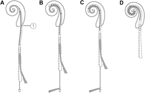
A second area of interest centers on optimizing the electrode-to-neuron interface through minimizing the distance between the stimulating electrode and the receiving neural cell groups. There are many theoretical advantages to perimodiolar positioning including lower energy requirements, a reduction in channel interactions, more discrete neural population stimulation, and less trauma during insertion. Earlier designs aimed at improving electrode position used large space–filling designs or incorporated “positioner” components. However, such attempts resulted in substantial trauma and have since been abandoned. One notable advance has been the introduction of precurved perimodiolar designs with accompanying insertion guides. Roland demonstrated that in comparison with conventional insertion techniques, the use of the AOS technique combined with a tapered soft-tip modification resulted in less insertional force and intracochlear trauma ( Fig. 4 ).
The early success of the multichannel electrode demonstrates the importance of improved spatial selectivity during stimulation. The number of largely independent filters used during normal hearing includes at least 28 for the frequency range covered by speech. Although today’s designs may include as many as 22 electrodes, the majority of users achieve less than 10 perceptually unique channels. Factors including electrode design, signal processing strategy, distance between stimulating electrode and modiolus, number and spatial distribution of surviving spiral ganglion cells, and intracochlear fibrosis may all limit spatial specificity during stimulation. Therefore, even when a large number of electrodes are available for use, such factors may limit the maximal number of discrete spiral ganglion cell populations that can be stimulated. It is interesting, however, that under testing conditions many users are able to discern frequency/pitch differences with each successive electrode along an entire array (as many as 22 physical electrodes or more using “virtual channels”). However, during real-time sound-processor use, even the highest performing subjects peak on objective performance testing with use of less than 10 perceptually independent channels, although more channels may permit improved subjective sound quality.
What does the future hold for electrode design? Drug-eluting designs and micropump delivery systems might allow for use of anti-inflammatory drugs that may lessen postimplant inflammation, reactive tissue formation, and neural-element degeneration. The use of neurotropic factors may prevent further neural degeneration associated with either electrode placement or progression of the underlying otologic disease, and may even allow for neural ingrowth allowing for improved electrode-to-neuron coupling. Robotic electrode insertion with steerable electrode arrays may minimize insertion variability and more consistently reduce traumatic array placement. There has been a renewed interest in intramodiolar electrode placement, with theoretical advantages including improved spatial resolution, lower energy requirements to achieve stimulus threshold, and a greater number of available stimulus sites. Finally, the use of pulsed optical stimulation may overcome issues of current spread seen with electrical stimulation and improve the spatial selectivity of stimulation.
Signal-Processing Strategies
Many of the performance improvements seen with conventional CIs over the last 2 decades can be directly attributed to the refinement of sound-coding strategies. Signal processing extracts and refines acoustic information to provide meaningful neural stimulation patterns that are palatable to the diseased inner ear and central auditory system.
Two important operations used by all current sound processors include signal compression and bandpass filtering. Normal hearing permits an approximate 120-dB dynamic range of stimulus amplitude with the ability to discern alterations of less than 1 dB, whereas the electric dynamic range of implant users is generally between 6 and 15 dB. Nonlinear signal compression seeks to reduce the output-to-input ratio, thereby narrowing the dynamic range to make it suitable for stimulation within the narrow spectrum of implant users. Bandpass filtering is another important processing step first introduced with multichannel implants. The frequency spectrum of interest for speech and other important environmental sound cues resides primarily between 100 and 8000 Hz. Selective frequency filtering removes unwanted information and allows for different frequencies to be applied to separate channels for independent processing along the corresponding neural frequency map of the cochlea (frequency-to-electrode matching).
The first commercially available single-channel CI (House/3 M) used a solitary compressed sinusoidal current. Early multichannel models subsequently adapted overlapping frequency bands with simultaneous stimulation. The next major development came from the discovery that formants, based on the resonance of the human vocal tract, could be selectively extracted and applied to specific electrodes corresponding to their matched modiolar frequency locations. The Nucleus Wearable Speech Processor was the earliest implant to implement formant use and adopted an F0F2 (F0, fundamental frequency; F2, second resonant frequency) strategy that provided more consistent open-set speech recognition.
Today there are multiple commonly used signal processing strategies used by the 3 main CI manufacturers. All commercially available pulsatile strategies are based on the Continuous-Interleaved-Sampling (CIS) strategy, which was first described by Wilson and colleagues in 1991. With CIS, a temporal envelope is extracted from several bandpass filters (5–20) and after nonlinear signal compression they are delivered to each electrode in nonoverlapping (or interleaved) pulses (>800 pulses per second per channel [pps/ch]). In other words, the pulse train is modulated with the temporal envelope of the incoming speech signal for any given filter bandpass. By using nonsimultaneous signal delivery, the CIS strategy is able to minimize problems associated with channel interaction. Advanced Bionics Corporation further developed several strategies based on the CIS blueprint. The Multiple Pulsatile Sampler (MPS), formerly known as the Paired Pulsatile Sampler (PPS), differs from the CIS strategy in that set electrodes pairs (1/5, 2/6, 3/7, 4/8) are designated so that the two electrodes within each pair stimulate in concert. By choosing relatively distant electrodes for each pair, the strategy reduces concerns of current summation. The MPS strategy also uses a faster stimulation rate (1445 pps/ch).
The “n-of-m” strategy is also based on the principles of CIS in that it uses bandpass filtering and temporal envelope extraction, but additionally integrates temporal frames lasting 2.5 to 4 milliseconds. Sound is sampled in sequential 2.5- to 4-millisecond intervals and is processed to several frequency bands. Within each interval, several bands with the highest envelope amplitude are selected and interleaved (∼1000 pps/ch) between corresponding electrodes. The Spectral Peak (SPEAK) and Advanced Combination Encoder (ACE) strategies were subsequently adapted by Cochlear Corporation from the n-of-m strategy. The SPEAK strategy estimates the envelope amplitude of 20 bandpass filters, and uses 6 to 10 bands containing the largest amplitudes while using a relatively low rate of stimulation (180–300 pps/ch). The ACE strategy alternatively identifies a discrete number of bands, called maxima (generally ranging from 8 to 12), from 22 bandpass filters, and is capable of a much faster stimulation rate (250–2400 pps/ch).
With all CIS-based strategies described here, the channel stimulation rate is not varied across electrodes. Recently, however, there has been interest in developing methods to deliver “fine-frequency” cues that are lacking in current envelope extraction–based strategies in hopes of improving hearing performance in noise, music appreciation, and other more complex listening tasks. Med-El’s Fine Structure Processing (FSP) strategy using FineHearing technology is based on envelope and fine-structure processing. Timing of stimulation is used to code the temporal structure of the sound signal through the use of channel-specific sampling sequences in the low to mid frequencies (apical channels, typically 70–300 Hz). In the remaining channels, fine-structure coding is accomplished through the use of sequential “virtual channels”; bandpass filters use a bell-shaped frequency response allowing for a gradual transition from one electrode to a neighboring electrode, thereby creating intermediate pitch percepts that are different than those created from stimulating any one electrode alone. Though not yet available in the United States, the FS4 and FS4-p (parallel stimulation) coding strategies are two further refined versions that provide fine-structure processing on 4 channels ranging up to 1000 Hz.
The current HR90 K implant system (Advanced Bionics Corp) implements another strategy called HiResolution Sound (HiRes). The HiRes platform offers a wide programmable dynamic range (up to 80 dB) and is capable of rapid stimulation rates (up to 83,000 pps/ch). Each individual electrode is powered and controlled independently, allowing the system to operate under a simultaneous (ie, paired) or a nonsimultaneous (ie, sequential) CIS-based strategy. The HiRes Fidelity 120 (HiRes 120) is designed to further improve spatial resolution of stimulation using “current steering” (also called “virtual channel”) techniques. By delivering simultaneous but varying amounts of current to neighboring electrode pairs, the number of stimulation sites can be increased beyond the actual number of discrete contacts (8 spectral bands assigned to 15 electrode pairs creating up to 120 spectral bands). Though not yet available in the United States, Advanced Bionics Corporation is currently trialing a signal enhancement algorithm, “ClearVoice,” built on HiRes Fidelity 120 technology. With this strategy, speech is distinguished from unwanted noise by analysis of amplitude changes over time. When noise is added to speech, the amplitude changes (modulations) are flattened. The ClearVoice noise reduction algorithm estimates the noise level in each frequency band in sequential time frames (1.3 seconds) and reduces the gain in frequency bands containing less ideal signal-to-noise ratios (SNR), thereby emphasizing those frequencies containing meaningful sound cues (ie, speech).
Finally, Cochlear Corporation has introduced an approach termed MP3000 (previously referred to as Psychoacoustic Advanced Combination Encoder [PACE]; not yet available in the United States) aimed at improving spectral resolution, which was adapted from the previously described ACE strategy. The MP3000 strategy differs from ACE and other related n-of-m strategies in that after selecting the largest envelope amplitudes, the masking pattern of the envelope is determined and the next largest acoustic component is used, thereby better emulating the masking capabilities of the normal hearing auditory system. The current Cochlear Corporation devices use a single current source and do not allow for simultaneous stimulation. Of note, in a white paper publication Cochlear Corporation demonstrated that sequential pulse pairs could create intermediate pitch percepts using the slopes from the overlapping of channel bandpass filters. In their study, up to 161 discernible pitches could be produced with a 22-electrode array.
Back Telemetry and Device Fitting
Following implant activation, implant programs must be fitted (or mapped) to guarantee optimal safe electric performance. Today’s processors can store multiple independent maps so that users can benefit from a choice of programs that are optimal for different auditory tasks in various environments. Programming is most time intensive during the first 3 to 6 months when regular corrections are required as the user adapts to electrical stimulation. The majority of adjustments involve correcting minimal threshold levels (T-level) and the maximum comfortable loudness levels termed the C-level (Cochlear Corp) or M-level (Advanced Bionics Corp and Med-El). The optimal dynamic range can be determined by setting current levels defining T- and C- or M-levels for each individual electrode.
The availability of objective internal device integrity and function testing remains critical for optimizing individual user outcomes. This aspect is especially crucial in young patients and those with poor language ability who are unable to communicate issues of abnormal sound perception or unpleasant nonauditory sensations. For these patients, telemetry testing may be the only method for screening electrode dysfunction. With earlier designs such as the Nucleus 22 device, acquiring averaged electrode voltage was the only objective means of assessing CI electrode integrity. Now all device manufacturers routinely fit new-generation implants with impedance and neural response telemetry.
Impedance telemetry assesses the electrode-tissue interface by measuring the resistance met across a closed-circuit loop. Open-circuit failures result from damage to individual channel lead wires and are characterized by excessively high impedances. Short-circuit failures, on the other hand, occur when there is a breach of insulation between two separate wires, and are characterized by low impedance values. Faulty channels disrupt speech perception performance and may result in undesirable nonauditory stimulation (facial nerve or vestibular system activation, and pain), or in the case of a short circuit an aberrant pitch percept, and therefore should be selectively excluded from the fitting strategy. Studies have found that multiple individual electrode failures (greater than 3 or 5) within an array may be a sign of impending device deterioration requiring future revision surgery.
First debuted in 1998 with FDA approval for the Nucleus 24 M implant (Cochlear Corp), Neural Response Telemetry (NRT) (Neural Response Imaging [NRI], Advanced Bionics or Auditory nerve Response Telemetry [ART], Med-El) is a tool used to measure electrically evoked compound action potentials (ECAP) after filtering out background artifact. ECAP thresholds generally lie between behaviorally measured T-levels and C-levels, and thus may be used to estimate initial settings or at least estimate the shape of the T- and/or C/M-level profile during fitting; however, behavioral-level testing remains the preferred method for those able to participate in testing. Beyond ECAP thresholds, electrically evoked stapedius reflex threshold testing may be another objective method available in the future for determining appropriate C- or M-levels for mapping.
In general, dynamic range determination and faulty channel exclusion are given the most weight during CI fitting while individualized frequency-to-electrode programming receives less attention. Current electrode designs and implantation strategies generally use a “one-size-fits-all” approach despite large variations in cochlear dimensions and angular insertion depth. At present, most implant users receive a default frequency-to-electrode allocation strategy that may result in considerable frequency mismatch, which could account for some of the variance seen between “star” implant users and those who perform poorly. Future approaches using novel software or imaging technologies may allow for customized frequency-to-electrode matching to improve speech perception performance.
Device Reliability and Safety
Internal device failure requiring reimplantation occurs in approximately 3% to 6% of all implantees, and represents the most commonly reported significant postoperative complication. Driving concepts of development may be at odds: electrodes must be durable and resist tip foldover, but at the same time should have a forgiving structure to allow for an atraumatic insertion; the internal device casing must be low profile and compact but at the same time must remain impact resistant and impervious to moisture. Enhanced device hermetics and design durability have resulted in an overall decrease in the frequency of spontaneous device malfunction ; however, the sheer number of implant surgeries performed every year ensures that device failure will remain a significant burden in the foreseeable future.
Whereas much attention has been given to device failures requiring reimplantation, few reports have investigated the incidence of individual electrode failures along an array. Because individual electrode anomalies generally do not require reimplantation and are simply managed by in-house channel deactivation, device reliability data generally fail to report such occurrences. Individual faulty electrodes can lead to deterioration in speech performance and unpleasant nonauditory stimulation, and may be a sign of impending total device failure. While a general decline in the number of total device failures related to failing hermeticity has been seen, the prevalence of individual electrode failures with successive implant models has not reliably declined. Previous studies have shown that even with modern designs, approximately 10% of implanted arrays will experience at least one individual electrode circuit failure. Moving forward, universal reporting and use of standardized terminology is critical to improving device design.
Device safety must remain a high priority with all new CI designs. CI development has benefited from the advances seen in other implantable device technologies, and tissue incompatibility and device exposure fortunately remain relatively uncommon. Beyond this, the CI carries a unique set theoretical concerns associated with intracochlear electrode placement and inner ear infection. The CI electrode traverses the middle ear space and enters the sterile environment of the inner ear. This process allows for the possibility of an ascending infection from the middle ear space to the cochlea, which could result in substantial loss of spiral ganglion cells and device-associated meningitis; this is particularly relevant in children in whom the incidence of otitis media is disproportionately high. There are many factors that may predispose implantees to meningitis including young age, dual-component electrodes, intracochlear trauma, cochleostomy design, and cochlear dysplasia. From a practical standpoint, these variables can be divided into “controllable” and “uncontrollable” factors. While uncontrollable anatomic and physiologic patient factors will likely maintain an inevitable low baseline rate of meningitis even despite proper vaccination, improvements in surgical technique and device design may result in an overall decreased rate of meningitis.
In 1999, a two-part electrode containing an integrated positioning device (first with C1.2 and later with HiFocus II) was introduced onto the market and was found to be associated with a 4.5-times increased risk for developing meningitis; this model was voluntarily removed from the market in 2003 and replaced with a positioner-free version. The increased risk with the positioner was attributed to greater intracochlear trauma and a larger cochleostomy requirement to accommodate the wider-diameter electrode. Cadaver studies demonstrated that the larger two-part electrode resulted in increased trauma to the osseous spiral lamina and modiolus, and animal studies corroborated that such trauma increases the risk for otogenic meningitis. It is now recommended that cochleostomy size and intracochlear trauma be minimized to decrease the risk of postimplant meningitis.
Stay updated, free articles. Join our Telegram channel

Full access? Get Clinical Tree


